EP0143692A1 - Method and device for checking and controlling the filling of a series of containers by a given weight of a product having a variable volumetric weight - Google Patents
Method and device for checking and controlling the filling of a series of containers by a given weight of a product having a variable volumetric weight Download PDFInfo
- Publication number
- EP0143692A1 EP0143692A1 EP84402269A EP84402269A EP0143692A1 EP 0143692 A1 EP0143692 A1 EP 0143692A1 EP 84402269 A EP84402269 A EP 84402269A EP 84402269 A EP84402269 A EP 84402269A EP 0143692 A1 EP0143692 A1 EP 0143692A1
- Authority
- EP
- European Patent Office
- Prior art keywords
- filling
- container
- volumetric
- product
- controlling
- Prior art date
- Legal status (The legal status is an assumption and is not a legal conclusion. Google has not performed a legal analysis and makes no representation as to the accuracy of the status listed.)
- Granted
Links
Images


Classifications
-
- B—PERFORMING OPERATIONS; TRANSPORTING
- B65—CONVEYING; PACKING; STORING; HANDLING THIN OR FILAMENTARY MATERIAL
- B65B—MACHINES, APPARATUS OR DEVICES FOR, OR METHODS OF, PACKAGING ARTICLES OR MATERIALS; UNPACKING
- B65B3/00—Packaging plastic material, semiliquids, liquids or mixed solids and liquids, in individual containers or receptacles, e.g. bags, sacks, boxes, cartons, cans, or jars
- B65B3/26—Methods or devices for controlling the quantity of the material fed or filled
Definitions
- the subject of the present invention is a method and a device for monitoring and controlling the chain filling of containers with a determined weight of product having a variable density.
- the device comprises means for controlling the transfer of the product from the volumetric dispenser to the container first at high speed on the first part of the second path of the carousel, then at reduced speed on the second part of the second path of the carousel
- the device comprises means for acting on the control member as a function of the stop point for filling the container on the second part of the second path of the carousel.
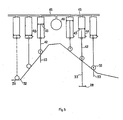
- Figure 1 are shown the different phases of the path of a container on a chain filling installation comprising a rotary carousel 3 equipped with several filling stations.
- the container is conveyed by a conveying means 1 to a distribution star 2 which introduces it at point 6 onto one of the filling stations of the carousel 3, which is driven in a rotational movement.
- a distribution star 2 which introduces it at point 6 onto one of the filling stations of the carousel 3, which is driven in a rotational movement.
- the container is tared, by resetting the balance to zero for example, while the filling of the volumetric metering device started at point 10 is completed.
- part of the volume of product contained in the volumetric dispenser is transferred with a rapid flow from the dispenser to the container.
- the transfer continues with a slower flow until the container contains the desired weight of product.
- the container is weighed continuously.
- a calculation and storage unit a microprocessor for example, continuously compares the weight of the product contained in the container with the desired weight and, when this desired weight is reached, orders the filling of the container to stop.
- the filled container then leaves the carousel 3 or tangentially to the carousel 3, on a conveying means 25 or else in a preferred direction, parallel to a conveying means 1 for example, via a distribution star 4 on a conveying means 5.
- FIG. 2 shows a schematic sectional view of an exemplary embodiment of a filling station.
- Each filling station is located on the rotary carousel 3 and comprises: an electronic balance 36; means 38 for centering a container 39; a hopper for supplying the product to be packaged 12; a volumetric metering device 37 comprising a piston 28 provided with sealing means 29, a cylinder 13 in which the piston 28 slides, a rod 33 actuating the piston 28.
- a distributor 14 comprising a body 19 and a cylindrical plug 18 capable of pivoting in the body 19.
- the body 19 has a horizontal bore of axis 27; a vertical duct 24 located in its upper part and opening on the one hand into the feed hopper 12 and on the other hand into the bore of axis 27; a vertical duct 26 located in its upper part and opening on the one hand into the volumetric metering device 37 and on the other hand into the bore of axis 27; a vertical bore of the same axis as the conduit 26, surmounting the latter and receiving the cylinder 13 of the volumetric metering device 37; a vertical duct 30 situated in its lower part and opening on the one hand into the bore of axis 27 and on the other hand above the container 39.
- the cylindrical plug '18 occupies the vertical bore of axis 27 of the body 19, in which it can pivot. It comprises a recess 15 which, in a determined position of the plug 18 relative to the body 19, connects the conduits 24 and 26 of the body 19; a cylindrical conduit 17, without communication with the recess 15, which, in another determined position of the plug 18 relative to the body 19, connects the conduits 26 and 30 of the body 19; a control lever 20 for pivoting the plug 18 inside the body 19. Electrical, pneumatic or equivalent means, not shown in the figure, act on the control lever 20 on the instructions communicated to them by the calculation and storage.
- the plug 18 When a filling station is located between points 10 and 7 of the path shown in Figure 1, the plug 18 is positioned so that the recess 15 faces the conduits 24 and 26 of the body 19 and the feed hopper 12 and the volumetric metering device 37 are in communication (case of FIG. 2). When a filling station is located between point 7 and the filling stop point located between points 8 and 9 of the path shown in Figure 1 the plug 18 is positioned so that the conduit 17 is facing the conduits 26 and 30 of the body 19 and the volumetric dispenser 37 and the container 39 are in communication.
- FIG. 4 represents a schematic developed view of a cam controlling the operation of two filling stations. It must be understood that in reality such a cam is not located in a plane but is wound on a cylinder with the same center as the carousel and that it controls a number of filling stations, variable depending on the case, but well above 2.
- the cam 34 shown in FIG. 4 comprises a rising ramp with two: successive inclinations: ramp 340 between points 10 and 6, ramp 341 between points 6 and 7; a downward ramp with two inclinations: ramp 342 between points 7 and 8, ramp 343 between points 8 and 9; a horizontal part 344 between points 9 and 10 (the numbering of these points corresponds to that of FIG. 1).
- the upward path corresponds to the filling of the volumetric dispenser 37.
- the downward path corresponds in part to the transfer of the product from the volumetric doser 37 into the container 39.
- the cam 34 is fixed relative to the rotary carousel 3 on which the filling stations are installed. It controls the operation of each of them by guiding a roller 32 secured to the rod 33 of the piston 28, by the interposition of elastic means 40 fixed on the one hand to the end of the rod 33, on the other hand to a fixed point 41 secured to the carousel.
- the elastic means 40 work in compression and keep the roller 32 in contact with the cam 34 which allows the guiding the roller 32 by the cam on the downward ramp thereof. They have another function: when the container 39 is filled with the desired weight of product, the calculation and storage unit controls the closing of the dispensing orifice of the volumetric dispenser. The stroke of the piston 28 is thereby interrupted.
- the roller 32 was guided along the descending ramp by rigid means, a rail parallel to the cam 34 coming into contact with the upper part of the roller, for example, damage would ensue.
- the elastic means 40 the compression force of which has been calculated so that it is greater than the resistance encountered by the piston of the volumetric dispenser when it drives the product into the container, but less than the resistant force exerted on the elastic means by the piston rod when it is blocked, absorb the excess travel of the piston.
- the roller 32 leaves the contact of the descending ramp of the cam at the point of filling the container and resumes contact with the rising ramp of the cam at a point situated in the same horizontal plane as the point where the filling of the container is stopped.
- the guiding of the roller 32 by the cam 34 with the interposition of elastic means also constitutes security for the filling installation: the accidental blocking of a piston does not cause any unfortunate consequence of the fact that the roller can escape from drug.
- the filling of the volumetric metering device 37 can be modified so that the point of stopping the filling of the container 39 takes place between points 8 and 9, that is to say on the descending ramp 343, when the filling rate is slow.
- FIG. 4 is shown a device, allowing the modification of the volume admitted into the volumetric metering device, constituted by a part of an ascending ramp 341 of the cam 34 with adjustable inclination, and a gear motor 25 actuating an endless screw 16.
- the inclination of the ramp part 341 is adjusted so that the point of stopping the filling of the containers takes place between points 8 and 9.
- the calculation and storage unit records the coordinates of the stop point for filling each container and check that it is on the ramp part 343. If for some reason or other a drift occurs and the stop point for filling the containers closer to point 8 or point 9 beyond determined set values, the calculation and storage unit would command a modification of the inclination of the ramp part 341, up or down depending on the direction drift.
- FIG. 5 represents an example of an embodiment of elastic means interposed between the cam 34 and the rod 33 of the piston of each volumetric metering device 37.
- the elastic means used in this example consist of a pneumatic cylinder comprising a cylinder 44 integral with the carousel 3 , a piston 43 sliding in the cylinder 44, a rod 42 fixed to the piston 43 at one end and secured to the roller 42 at the other end.
- the pneumatic cylinder of each filling station is connected to the cylinder of all the other filling stations and has a buffer volume 46 by a pipe 45.
- Figure 6 shows the sectional view of another embodiment of elastic means interposed between the cam 34 and the rod 33 of the piston.de each volumetric metering device.
- the piston 28 of the volumetric metering device 37 is surmounted by a cylindrical part 47 having a bore intended to guide the end of the rod 33.
- the rod 33 has a vertical slot 48. It enters the bore of the cylindrical part 47 where it can slide vertically between two extreme positions defined by the light 48, light which passes a horizontal pin 5 0 jack at both ends in the cylindrical portion 47.
- on the rod 33 is fixed in addition, by a pin 51, a ring 49 having a shoulder.
- a spring 52 working in compression is disposed between the ring 49 and the piston 28 along the axis of the rod 33.
Abstract
Description
La présente invention a pour objet un procédé et un dispositif de contrôle et de commande du remplissage à la chaîne de récipients par un poids déterminé de produit ayant un poids volumique variable.The subject of the present invention is a method and a device for monitoring and controlling the chain filling of containers with a determined weight of product having a variable density.
Dans de nombreuses industries, telles que les industries agro-alimentaire, pétrolière, pharmaceutique, chimique, par exemple, on a besoin de conditionner des produits liquides ou pâteux de poids volumique variable, cette variation de poids volumique pouvant être due soit à la dilatation ou à la rétraction de produits homogènes soumis à des variations de température soit à la nature même des produits quand ils sont hétérogènes. Un problème se pose lorsqu'on se propose de remplir à la chaîne des récipients avec un poids déterminé de tels produits.In many industries, such as the food industry, petroleum, pharmaceutical, chemical, for example, there is a need to package liquid or pasty products of variable density, this variation in density may be due to either expansion or to the shrinkage of homogeneous products subjected to temperature variations or to the very nature of the products when they are heterogeneous. A problem arises when it is proposed to fill the chain containers with a determined weight of such products.
Si l'on utilise des installations de remplissage équipées de doseurs volumétriques, il est nécessaire de surdoser le produit à conditionner de façon que, dans le cas le plus défavorable, c'est-à-dire le cas où le poids volumique du produit est le plus faible, les récipients contiennent exactement le poids de produit désiré.If filling installations equipped with volumetric dosers are used, it is necessary to overdose the product to be packaged so that, in the most unfavorable case, that is to say the case where the density of the product is the weakest, the containers contain exactly the desired weight of product.
Ce surdosage nécessaire pour garantir au moins le poids de produit désiré dans chaque récipient entraîne un manque à gagner pour le fabricant du produit, puisque les excédents s'additionnant, c'est un volume non négligeable de produit qui est distribué sans être vendu.This overdose necessary to guarantee at least the desired weight of product in each container leads to a shortfall for the manufacturer of the product, since the surpluses add up, it is a significant volume of product which is distributed without being sold.
Si l'on utilise des installations de remplissage à dosage pondéral comportant une balance fixe sur laquelle les récipients sont remplis et pesés l'un après l'autre, on n'a plus à tenir compte des variations de poids volumique. Cependant, dans la pratique, on se heurte à plusieurs difficultés. Pour être précis le pesage du récipient doit durer un temps minimal. Or ce temps minimal est supérieur à la durée de remplissage de chaque récipient que permettent les installations de remplissage à cadence élevée comme celles qui sont utilisées pour le conditionnement de la confiture par exemple. (Le diamètre de l'orifice des pots de confiture étant important, leur remplissage est très rapide) . En outre, ce temps minimal de présence du récipient sur la balance peut être augmenté si l'on utilise des récipients dont le poids varie d'un récipient à l'autre, ce qui est le cas des récipients de verre notamment, car il est nécessaire d'effectuer le tarage de chaque récipient. (On pourrait naturellement s'affranchir de la nécessité de tarer chaque récipient en surdosant le produit à conditionner de façon à couvrir la variation du poids des récipients mais ce serait retrouver les inconvénients présentés par les installations de remplissage à dosage volumétrique). Avec de telles installations de remplissage on se trouve donc devant la nécessité ou de réduire la cadence de remplissage pour permettre le pesage précis du contenu de chaque récipient et éventuellement le tarage de chaque récipient ou, si on décide de maintenir la cadence de remplissage, de se contenter d'un pesage approximatif, - mais il faut alors surdoser le produit à conditionner pour être assuré que chaque récipient l'invention concernant les installations de remplissage où le débit de remplissage est rapide dans une première phase, plus lent dans une seconde phase, la première ayant une durée prédéterminée, la position du point d'arrêt du remplissage d'un récipient sur l'e trajet de remplissage est utilisée pour modifier éventuellement le volume de produit à introduire dans le doseur volumétrique du poste de remplissage d'un récipient ultérieur de façon que le remplissage de ce dernier s'achève pendant la phase où le débit du remplissage est lent.If we use filling systems with weight dosing comprising a fixed scale on which the containers are filled and weighed one after the other, we no longer have to take account of variations in density. However, in practice, there are several difficulties. To be precise, the weighing of the container must last a minimum time. However, this minimum time is greater than the duration of filling of each container that high-speed filling installations such as those used for packaging jam allow. (The diameter of the orifice of the jars of jam being important, their filling is very fast). In addition, this minimum time of presence of the container on the scale can be increased if containers are used whose weight varies from one container to another, which is the case for glass containers in particular, because it is necessary to tare each container. (One could naturally get rid of the need to tare each container by overdosing the product to be packaged so as to cover the variation in the weight of the containers but this would find the disadvantages presented by filling installations with volumetric dosing). With such filling installations, we therefore find ourselves faced with the need to reduce the filling rate to allow precise weighing of the contents of each container and possibly the taring of each container or, if we decide to maintain the filling rate, be content with an approximate weighing, - but you must then overdose the product to be packaged to be sure that each container the invention relates to filling installations where the filling rate is rapid in a first phase, slower in a second phase, the first having a predetermined duration, the position of the point of filling stop of a container on the The filling path is used to possibly modify the volume of product to be introduced into the volumetric dispenser of the filling station of a subsequent container so that the filling of the latter ends during the phase when the filling rate is slow.
Pour la mise en oeuvre du procédé décrit ci-dessus on prévoit selon l'invention un dispositif tel que :
- - chaque poste de remplissage comporte un doseur volumétrique pour recevoir un volume déterminé de produit sur un premier trajet du carrousel et transférer une partie de ce volume dans un récipient sur un second trajet du carrousel;
- - chaque poste de remplissage comporte une balance qui se déplace avec le poste pour peser un récipient continûment avant et pendant son remplissage;
- - l'installation comporte un organe de commande pour commander le remplissage de chaque doseur volumétrique pendant le premier trajet du carrousel et le transfert d'une partie de son contenu dans un récipient pendant le second trajet du carrousel;
- - l'installation comporte un organe de calcul et de mise en mémoire pour effectuer le tarage du récipient, pour comparer continûment le poids du récipient à la valeur de consigne, pour commander l'arrêt du remplissage quand le poids du contenu du récipient atteint ladite valeur de consigne;
- - chaque poste comporte des moyens élastiques interposés entre l'organe de commande et le doseur volumétrique pour reprendre les efforts anormaux résultant de la fermeture de l'orifice de distribution dudit doseur volumétrique avant l'écoulement du volume total de produit contiendra au moins le poids désiré (et l'on retrouve à nouveau les inconvénients présentés par les installations de remplissage à dosage volumétrique). Dans un cas comme dans l'autre la solution adoptée n'est pas pleinement satisfaisante puisqu'elle se traduit toujours, - perte de temps ou perte de produit -, par un manque à gagner.
- - Each filling station includes a volumetric dispenser for receiving a determined volume of product on a first path of the carousel and transferring part of this volume in a container on a second path of the carousel;
- - each filling station has a scale which moves with the station to weigh a container continuously before and during filling;
- - The installation comprises a control member for controlling the filling of each volumetric dispenser during the first journey of the carousel and the transfer of part of its content in a container during the second journey of the carousel;
- the installation comprises a calculation and storage member for taring the container, for continuously comparing the weight of the container with the set value, for controlling the stopping of the filling when the weight of the contents of the container reaches said setpoint;
- - Each station has elastic means interposed between the control member and the volumetric dispenser to resume the abnormal forces resulting from the closure of the dispensing orifice of said volumetric dispenser before the total volume of product has run out. will contain at least the desired weight (and we again find the disadvantages presented by volumetric filling systems). In either case, the solution adopted is not fully satisfactory since it always results, - loss of time or loss of product - , by a shortfall.
Un objet de la présente invention est un procédé de contrôle et de commande du remplissage de récipients engagés successivement dans une installation de remplissage comportant un élément de type carrousel rotatif à plusieurs postes de remplissage recevant chacun un récipient pour le remplir avec un produit selon un dosage pondéral désiré, caractérisé par les opérations suivantes :
- - un doseur volumétrique associé à chaque poste reçoit un volume de produit dont le poids est légèrement supérieur à une valeur de consigne;
- - le produit contenu dans le doseur volumétrique associé à chaque poste est transféré dudit doseur volumétrique dans un récipient sous l'effet d'un organe de commande, avec interposition de moyens élastiques;
- - chaque récipient engagé sur un poste de remplissage est taré puis pesé pendant qu'il est rempli une balance se déplaçant avec chaque poste de remplissage;
- - le poids du contenu de chaque récipient est comparé tout au long du remplissage à la valeur de consigne;
- - le remplissage de chaque récipient est stoppé par fermeture de l'orifice de distribution du doseur volumétrique lorsque le poids de son contenu atteint la valeur de consigne;
- - les efforts anormaux résultant de la fermeture de l'orifice de distribution du doseur volumétrique avant l'écoulement du volume total de produit qui a été initialement introduit dans ledit doseur volumétrique sont repris par les moyens élastiques interposés entre l'organe de commande et le doseur volumétrique.
- - a volumetric dispenser associated with each station receives a volume of product whose weight is slightly greater than a set value;
- - The product contained in the volumetric dispenser associated with each station is transferred from said volumetric dispenser in a container under the effect of a control member, with the interposition of elastic means;
- each container engaged on a filling station is tared and then weighed while it is filled, a balance moving with each filling station;
- - the weight of the contents of each container is compared throughout the filling with the set value;
- - the filling of each container is stopped by closing the dispensing orifice of the volumetric dispenser when the weight of its contents reaches the set value;
- - the abnormal forces resulting from the closure of the dispensing orifice of the volumetric dispenser before the flow of the total volume of product which was initially introduced into said volumetric dispenser are taken up by the elastic means interposed between the control member and the volumetric dispenser.
Suivant une caractéristique du procédé selon qui y a été initialement introduit.According to a characteristic of the process according to that was originally introduced there.
Suivant une caractéristique du dispositif selon l'invention concernant les installations de remplissage où l'organe de commande comporte des moyens pour commander le transfert du produit du doseur volumétrique au récipient d'abord à grande vitesse sur la première partie du second trajet du carrousel, ensuite à vitesse réduite sur la seconde partie du second trajet du carrousel, le dispositif comporte des moyens pour agir sur l'organe de commande en fonction du point d'arrêt de remplissage du récipient sur la seconde partie du second trajet du carrousel.According to a characteristic of the device according to the invention concerning the filling installations where the control member comprises means for controlling the transfer of the product from the volumetric dispenser to the container first at high speed on the first part of the second path of the carousel, then at reduced speed on the second part of the second path of the carousel, the device comprises means for acting on the control member as a function of the stop point for filling the container on the second part of the second path of the carousel.
D'autres caractéristiques et avantages de la présente invention apparaîtront mieux à la lecture de la description suivante faite en liaison avec les dessins ci-joints parni lesquels :
- La figure 1 est une vue de dessus schématique d'une installation de remplissage comportant un élément de type carrousel rotatif, où ont été représentées les différentes phases du cheminement d'un récipient ou un poste de remplissage;
- La figure 2 est une vue en coupe schématique d'un exemple de réalisation d'un poste de remplissage: La figure 3 est une vue en coupe schématique selon la ligne II-II de l'exemple de réalisation d'un poste de remplissage représenté sur la figure 2, la trémie d'alimentation et le doseur volumétrique n'étant pas représentés;
- La figure 4 est une vue schématique développée d'une came et de deux postes de remplissage, celui de gauche étant représenté sur le premier trajet de la came, celui de droite sur la première partie du second trajet de la came;
- La figure 5 est une vue schématique développée de la came et de quelques vérins pneumatiques interposés entre ladite came et les doseurs volumêtriques (non représentés sur cette figure) et reliés entre eux par une canalisation à un volume tampon; et
- La figure 6 est une vue en coupe d'un exemple de réalisation de moyens élastiques interposés entre la came et le doseur volumétrique.
- Figure 1 is a schematic top view of a filling installation comprising an element of the rotary carousel type, where have been shown the different phases of the movement of a container or a filling station;
- Figure 2 is a schematic sectional view of an embodiment of a filling station: Figure 3 is a schematic sectional view along line II-II of the embodiment of a filling station shown in FIG. 2, the feed hopper and the volumetric dispenser not being shown;
- Figure 4 is a schematic developed view of a cam and two filling stations, the left one being shown on the first path of the cam, the right one on the first part of the second path of the cam;
- Figure 5 is a schematic developed view of the cam and a few pneumatic cylinders interposed between said cam and the volumetric metering devices (not shown in this figure) and connected together by a pipe to a buffer volume; and
- Figure 6 is a sectional view of an embodiment of elastic means interposed between the cam and the volumetric metering device.
Sur la figure 1 sont représentées les différentes phases du trajet d'un récipient sur une installation de remplissage à la chaîne comportant un carrousel rotatif 3 équipé de plusieurs postes de remplissage. Le récipient est acheminé par un moyen de convoyage 1 vers une étoile de distribution 2 qui l'introduit au point 6 sur l'un des postes de remplissage du carrousel 3, lequel est animé d'un mouvement de rotation. Entre le point 6 et le point 7 le récipient est taré, par remise de la balance à zéro par exemple, tandis que s'achève le remplissage du doseur volumétrique commencé au point lO. Entre le point 7 et le point 8 une partie du volume de produit contenu dans le doseur volumétrique est transféré avec un débit rapide du doseur dans le récipient. Entre le point 8 et un point situé avant le point 9 le transfert se poursuit avec un débit plus lent jusqu'à ce que le récipient contienne le poids de produit désiré. Entre le point 7 et le point d'arrêt du remplissage, qui selon une caractéristique particulière de l'invention est calculé pour intervenir entre le point 8 et le point 9, le récipient est pesé continûment. Un organe de calcul et de mise en mémoire, un microprocesseur par exemple, compare continûment le poids du produit contenu dans le récipient au poids désiré et, quand ce poids désiré est atteint,commande l'arrêt du remplissage du récipient. Le récipient rempli quitte ensuite le carrousel 3 ou bien tangentiellement au carrousel 3, sur un moyen de convoyage 25 ou bien selon une direction préférentielle, parallèlement au un moyen de convoyage 1 par exemple, par l'intermédiaire d'une étoile de distribution 4 sur un moyen de convoyage 5.In Figure 1 are shown the different phases of the path of a container on a chain filling installation comprising a
La figure 2 représente une vue en coupe schématique d'un exemple de réalisation d'un poste de remplissage. Chaque poste de remplissage est situé sur le carrousel rotatif 3 et comporte : une balance électronique 36; des moyens 38 pour centrer un récipient 39; une trémie d'alimentation du produit à conditionner 12; un doseur volumétrique 37 comportant un piston 28 muni de moyens d'étanchéité 29,un cylindre 13 dans lequel coulisse le,piston 28,une tige 33 actionnant le piston 28. ün distributeur 14 comportant un corps 19 et un boisseau cylindrique 18 susceptible de pivoter dans le corps 19.Figure 2 shows a schematic sectional view of an exemplary embodiment of a filling station. Each filling station is located on the
Le corps 19 comporte un alésage horizontal d'axe 27; un conduit vertical 24 situé dans sa partie supérieure et débouchant d'une part dans la trémie d'alimentation 12 et d'autre part dans l'alésage d'axe 27; un conduit vertical 26 situé dans sa partie supérieure et débouchant d'une part dans le doseur volumétrique 37 et d'autre part dans l'alésage d'axe 27; un alésage vertical de même axe que le conduit 26, surmontant celui-ci et recevant le cylindre 13 du doseur volumétrique 37; un conduit vertical 30 situé dans sa partie inférieure et débouchant d'une part dans l'alésage d'axe 27 et d'autre part au-dessus du récipient 39.The
Le boisseau cylindrique '18 occupe l'alésage vertical d'axe 27 du corps 19, dans lequel il peut pivoter. Il comporte un évidement 15 qui, dans une position déterminée du boisseau 18 par rapport au corps 19, met en communication les conduits 24 et 26 du corps 19; un conduit cylindrique 17, sans communication avec l'évidement 15, qui, dans une autre position déterminée du boisseau 18 par rapport au corps 19, met en communication les conduits 26 et 30 du corps 19; un levier de commande 20 pour faire pivoter le boisseau 18 à l'intérieur du corps 19. Des moyens électriques, pneumatiques ou équivalents,non représentés sur la figure, agissent sur le levier de commande 20 sur les instructions que leur communique l'organe de calcul et de mise en mémoire.The cylindrical plug '18 occupies the vertical bore of axis 27 of the
Lorsqu'un poste de reuplissage se trouve entre les points 10 et 7 du trajet représenté sur la figure 1, le boisseau 18 est positionné de façon que l'évidement 15 soit en regard des conduits 24 et 26 du corps 19 et la trémie d'alimentation 12 et le doseur volumétrique 37 sont en communication (cas de la figure 2). Lorsqu'un poste de remplissage se trouve entre le point 7 et le point d'arrêt du remplissage situé entre les points 8 et 9 du trajet représenté sur la figure 1 le boisseau 18 est positionné de façon que le conduit 17 soit en regard des conduits 26 et 30 du corps 19 et le doseur volumétrique 37 et le récipient 39 sont en communication.When a filling station is located between
La figure 4 représente une vue développée schématique d'une came commandant le fonctionnement de deux postes de remplissage. Il faut bien concevoir que dans la réalité une telle came n'est pas située dans un plan mais s'enroule sur un cylindre de même centre que le carrousel et qu'elle commande un nombre de postes de remplissage, variable selon les cas, mais bien supérieur à 2.FIG. 4 represents a schematic developed view of a cam controlling the operation of two filling stations. It must be understood that in reality such a cam is not located in a plane but is wound on a cylinder with the same center as the carousel and that it controls a number of filling stations, variable depending on the case, but well above 2.
La came 34 représentée en figure 4 comporte une rampe montante à deux: inclinaisons successives : rampe 340 entre les points 10 et 6, rampe 341 entre les points 6 et 7; une rampe descendante à deux inclinaisons : rampe 342 entre les points 7 et 8, rampe 343 entre les points 8 et 9; une partie horizontale 344 entre les points 9 et 10 (la numérotation de ces points correspond à celle de la figure 1). Le trajet montant correspond au remplissage du doseur volumétrique 37. Le trajet descendant correspond pour une part au transfert du produit du doseur volumétrique 37 dans le récipient 39.The
La came 34 est-fixe par rapport au carrousel rotatif 3 sur lequel sont installés les postes de remplissage. Elle commande le fonctionnement de chacun d'eux en guidant un galet 32 assujetti à la tige 33 du piston 28,par l'interposition de moyens élastiques 40 fixés d'une part à l'extrémité de la tige 33, d'autre part à un point fixe 41 solidaire du carrousel. Les moyens élastiques 40 travaillent en compression et maintiennent le galet 32 en contact avec la came 34 ce qui permet le guidage du galet 32 par la came sur la rampe descendante de celle-ci. Ils ont une autre fonction : lorsque le récipient 39 est rempli par le poids de produit désiré, l'organe de calcul et de mise en mémoire commande la fermeture de l'orifice de distribution du doseur volumétrique. La course du piston 28 s'en trouve interrompue. Si le galet 32 était guide le long de la rampe descendante par des moyens rigides, un rail parallèle à la came 34 venant au contact de la partie supérieure du galet, par exemple, des dégâts s'en suivraient. Alors que les moyens élastiques 40, dont la force de compression a été calculée de façon qu'elle soit supérieure à la résistance que rencontre le piston du doseur volumétrique lorsqu'il chasse le produit dans le récipient,mais inférieure à la force résistante exercée sur les moyens élastiques par la tige du piston quand elle est-bloquée , absorbent l'excédent de course du piston.Le galet 32 quitte le contact de la rampe descendante de la came au point d'arrêt du remplissage du récipient et reprend contact avec la rampe montante de la came en un point situé dans le même plan horizontal que le point d'arrêt du remplissage du récipient. Naturellement, le guidage du galet 32 par la came 34 avec interposition de moyens élastiques constitue en outre une sécurité pour l'installation de remplissage : le blocage accidentel d'un piston n'entraîne pas de conséquence fâcheuse du fait que le galet peut échapper de la came.The
Selon une variante de la présente invention on peut modifier le remplissage du doseur volumétrique 37 pour que le point d'arrêt du remplissage du récipient 39 ait lieu entre les points 8 et 9, c'est-à-dire sur la rampe descendante 343, au moment où le débit de remplissage est lent. Sur la figure 4 est représenté un dispositif, permettant la modification du volume admis dans le doseur volumétrique, constitué par une partie de rampe montante 341 de la came 34 à inclinaison réglable, et un moto- réducteur 25 actionnant une vis sans fin 16. Lors de la mise en service de l'installation l'inclinaison de la partie de rampe 341 est réglée de façon que le point d'arrêt du remplissage des récipients ait lieu entre les points 8 et 9. L'organe de calcul et de mise en mémoire enregistre les coordonnées du point d'arrêt du remplissage de chaque récipient et contrôle qu'il se trouve sur la partie de rampe 343. Si pour une raison ou pour une autre une dérive se produisait et que le point d'arrêt du remplissage des récipients se rapprochât du point 8 ou du point 9 au delà de valeurs de consigne déterminées, l'organe de calcul et de mise en mémoire commanderait une modification de l'inclinaison de la partie de rampe 341, vers le haut ou vers le bas selon le sens de la dérive.According to a variant of the present invention, the filling of the
La figure .5 représente un exemple de réalisation de moyens élastiques interposés entre la came 34 et la tige 33 du piston de chaque doseur volumétrique 37. Les moyens élastiques utilisés dans cet exemple sont constitués par un vérin pneumatique comportant un cylindré 44 solidaire du carrousel 3, un piston 43 coulissant dans le cylindre 44, une tige 42 fixée au piston 43 à une extrémité et assujettie au galet 42 à l'autre extrémité. Le vérin pneumatique de chaque poste de remplissage est relié au vérin de tous les autres postes de remplissage et a un volume tampon 46 par une conduite 45.FIG. 5 represents an example of an embodiment of elastic means interposed between the
La figure 6 représente la vue en coupe d'un autre exemple de réalisation de moyens élastiques interposés entre la came 34 et la tige 33 du piston.de chaque doseur volumétrique. Le piston 28 du doseur volumétrique 37 est surmonté d'une partie cylindrique 47 comportant un alésage destiné à guider l'extrémité de la tige 33. La tige 33 comporte une lumière verticale 48. Elle pénètre dans l'alésage de la partie cylindrique 47 où elle peut coulisser verticalement entre deux positions extrêmes définies par la lumière 48, lumière dans laquelle passe une goupille horizontale 50 prise à ses deux extrémités dans la partie cylindrique 47. Sur la tige 33 est fixée en outre, par une goupille 51, une bague 49 comportant un épaulement. Un ressort 52 travaillant en compression est disposé entre la bague 49 et le piston 28 selon l'axe de la tige 33.Il prend appui à une extrémité sur la partie supérieure du piston 28, à l'autre extrémité dans l'épaulement de la bague 49, et est guidé par la surface extérieure de la partie cylindrique 33. Avec une telle disposition des moyens élastiques, on peut utiliser, pour guider le galet 32 sur la rampe descendante de la came, un rail rigide parallèle à la came 34 venant au contact de la partie supérieure du galet.Figure 6 shows the sectional view of another embodiment of elastic means interposed between the
La présente invention n'est pas limitée aux exemples de réalisation qui viennent d'être décrits, elle est au contraire susceptible de modifications et de variantes qui apparaîtront à l'homme de l'art.The present invention is not limited to the exemplary embodiments which have just been described, it is on the contrary liable to modifications and variants which will appear to those skilled in the art.
Claims (7)
Priority Applications (1)
| Application Number | Priority Date | Filing Date | Title |
|---|---|---|---|
| AT84402269T ATE33469T1 (en) | 1983-11-18 | 1984-11-09 | METHOD AND APPARATUS FOR MONITORING AND CONTROLLING THE FILLING OF A SERIES OF CONTAINERS OF A DETERMINED WEIGHT OF A PRODUCT OF ALTERNATING VOLUMETRIC WEIGHT. |
Applications Claiming Priority (2)
| Application Number | Priority Date | Filing Date | Title |
|---|---|---|---|
| FR8318417 | 1983-11-18 | ||
| FR8318417A FR2555132B1 (en) | 1983-11-18 | 1983-11-18 | METHOD FOR FILLING A CONTAINER WITH A SPECIFIED QUANTITY OF PRODUCT |
Publications (2)
| Publication Number | Publication Date |
|---|---|
| EP0143692A1 true EP0143692A1 (en) | 1985-06-05 |
| EP0143692B1 EP0143692B1 (en) | 1988-04-13 |
Family
ID=9294298
Family Applications (1)
| Application Number | Title | Priority Date | Filing Date |
|---|---|---|---|
| EP84402269A Expired EP0143692B1 (en) | 1983-11-18 | 1984-11-09 | Method and device for checking and controlling the filling of a series of containers by a given weight of a product having a variable volumetric weight |
Country Status (10)
| Country | Link |
|---|---|
| US (1) | US4635688A (en) |
| EP (1) | EP0143692B1 (en) |
| JP (1) | JPH0627662B2 (en) |
| AT (1) | ATE33469T1 (en) |
| BR (1) | BR8405869A (en) |
| CA (1) | CA1232883A (en) |
| DE (1) | DE3470401D1 (en) |
| ES (1) | ES8601046A1 (en) |
| FR (1) | FR2555132B1 (en) |
| ZA (1) | ZA848851B (en) |
Families Citing this family (9)
| Publication number | Priority date | Publication date | Assignee | Title |
|---|---|---|---|---|
| DE3630077A1 (en) * | 1986-09-04 | 1988-03-17 | Benz & Hilgers Gmbh | DEVICE FOR SIMULTANEOUSLY DOSED FILLING OF LIQUID OR SOFT PLASTIC SUBSTANCES LIKE BUTTER, MARGARINE, PASTE OR THE LIKE CONTAINERS CONTAINED ABOVE Mouthpieces |
| US4817683A (en) * | 1987-07-01 | 1989-04-04 | Laub Engineering Corporation | Adjustable automatic accurate container filling machine |
| DE3938220A1 (en) * | 1989-11-17 | 1991-05-23 | Benz & Hilgers Gmbh | METHOD AND DEVICE FOR PACKING PASTOESE PRODUCTS, LIKE SOUP PASTE, MARGARINE, BUTTER OR THE LIKE. IN THE FORM OF PACKAGES, CUBES OR THE LIKE |
| DE4117287A1 (en) * | 1991-05-27 | 1992-12-03 | Seitz Enzinger Noll Masch | METHOD FOR FILLING BOTTLES, CAN OR THE LIKE CONTAINED AND FILLING MACHINE FOR CARRYING OUT THIS PROCESS |
| US5280815A (en) * | 1992-05-05 | 1994-01-25 | Prc | Product filling machine |
| US5356041A (en) * | 1993-03-23 | 1994-10-18 | Fluid Management Limited Partnership | Dispensing apparatus having improved valving |
| IT1285580B1 (en) * | 1996-03-04 | 1998-06-18 | Mg 2 Spa | METHOD FOR WEIGHT CONTROL IN DOSING MACHINES AND MULTIPLE DOSING OF PRODUCTS IN GRANULES AND DOSING MACHINE THAT IMPLEMENTS THE |
| US5921759A (en) * | 1997-10-14 | 1999-07-13 | Sandeep Khan | Liquid metering piston pump and valves capable of being cleaned and sterilized without disassembly |
| DE10001068C1 (en) * | 2000-01-13 | 2001-05-31 | Bosch Gmbh Robert | Powder dosing and delivery device for filling gelatin capsules uses detection of spring path of reciprocating stamp for monitoring powder quantity |
Citations (1)
| Publication number | Priority date | Publication date | Assignee | Title |
|---|---|---|---|---|
| US2925835A (en) * | 1958-03-31 | 1960-02-23 | Kartridg Pak Machine Co | Automatic filling and weight checking machine |
Family Cites Families (15)
| Publication number | Priority date | Publication date | Assignee | Title |
|---|---|---|---|---|
| US1726297A (en) * | 1923-04-23 | 1929-08-27 | Hansen Canning Machinery Corp | Apparatus for treating kraut |
| US2280614A (en) * | 1939-01-17 | 1942-04-21 | Harry D Ayars | Filling machine |
| US2321994A (en) * | 1939-12-11 | 1943-06-15 | Frank D Chapman | Receptacle filler |
| US2961013A (en) * | 1958-04-28 | 1960-11-22 | Texaco Inc | Positive displacement type fluid filling machine having automatic cam track adjustingmeans and method of filling |
| US3189062A (en) * | 1961-07-26 | 1965-06-15 | Cherry Burrell Corp | Filling machine |
| US3240146A (en) * | 1962-11-20 | 1966-03-15 | Swift & Co | Controls for ham pumping |
| GB1023469A (en) * | 1962-12-13 | 1966-03-23 | Holstein & Kappert Maschf | Apparatus for controlling pumps for filling containers with liquid |
| FR1563577A (en) * | 1967-06-14 | 1969-04-11 | ||
| CH570932A5 (en) * | 1973-10-10 | 1975-12-31 | Rieter Ag Maschf | |
| US4060109A (en) * | 1976-05-14 | 1977-11-29 | Kewpie Kabushiki Kaisha | Filling quantity regulating system in container filling apparatus |
| US4060106A (en) * | 1976-05-21 | 1977-11-29 | Kewpie Kabushiki Kaisha | Method and system for preventing containerless discharging of filling material in container filling apparatus |
| US4244404A (en) * | 1979-02-12 | 1981-01-13 | Domain Industries, Inc. | Rotary piston filler |
| JPS56113528A (en) * | 1980-02-05 | 1981-09-07 | Dainippon Printing Co Ltd | Germless filling method |
| US4337802A (en) * | 1980-09-30 | 1982-07-06 | Velasco Scale Company, Inc. | Method and apparatus for liquid filling of containers |
| FR2493800A1 (en) * | 1980-11-13 | 1982-05-14 | Serac Sa | METHOD AND DEVICE FOR CONTROLLING FILLING MATERIALS IN A FULLY-DOSED FILLING MACHINE |
-
1983
- 1983-11-18 FR FR8318417A patent/FR2555132B1/en not_active Expired
-
1984
- 1984-11-09 DE DE8484402269T patent/DE3470401D1/en not_active Expired
- 1984-11-09 EP EP84402269A patent/EP0143692B1/en not_active Expired
- 1984-11-09 AT AT84402269T patent/ATE33469T1/en not_active IP Right Cessation
- 1984-11-13 ZA ZA848851A patent/ZA848851B/en unknown
- 1984-11-15 US US06/671,667 patent/US4635688A/en not_active Expired - Fee Related
- 1984-11-16 ES ES537739A patent/ES8601046A1/en not_active Expired
- 1984-11-16 CA CA000468079A patent/CA1232883A/en not_active Expired
- 1984-11-16 BR BR8405869A patent/BR8405869A/en not_active IP Right Cessation
- 1984-11-17 JP JP59243140A patent/JPH0627662B2/en not_active Expired - Lifetime
Patent Citations (1)
| Publication number | Priority date | Publication date | Assignee | Title |
|---|---|---|---|---|
| US2925835A (en) * | 1958-03-31 | 1960-02-23 | Kartridg Pak Machine Co | Automatic filling and weight checking machine |
Also Published As
| Publication number | Publication date |
|---|---|
| ES537739A0 (en) | 1985-10-16 |
| FR2555132B1 (en) | 1986-03-28 |
| ATE33469T1 (en) | 1988-04-15 |
| US4635688A (en) | 1987-01-13 |
| BR8405869A (en) | 1985-09-17 |
| ZA848851B (en) | 1985-06-26 |
| JPS60155927A (en) | 1985-08-16 |
| DE3470401D1 (en) | 1988-05-19 |
| EP0143692B1 (en) | 1988-04-13 |
| CA1232883A (en) | 1988-02-16 |
| ES8601046A1 (en) | 1985-10-16 |
| FR2555132A1 (en) | 1985-05-24 |
| JPH0627662B2 (en) | 1994-04-13 |
Similar Documents
| Publication | Publication Date | Title |
|---|---|---|
| EP0500831B1 (en) | Method and device for controlling the amounts dosed and dispensed by a dosing/dispensing apparatus | |
| EP2186761B1 (en) | Combined palletisation facility with secure access. | |
| EP0143692B1 (en) | Method and device for checking and controlling the filling of a series of containers by a given weight of a product having a variable volumetric weight | |
| EP2328824B1 (en) | Method and device for positioning containers and plant for treating containers having different cross sections | |
| FR2554801A1 (en) | CAPPING APPARATUS | |
| EP1474331B1 (en) | Installation for filling containers according to variable product compositions | |
| EP0001196A1 (en) | Device for the automatic control of a filling apparatus for receptacles | |
| EP0115989B1 (en) | Method for automatically filling and closing containers, and machine for carrying out the method | |
| EP0147263B1 (en) | Method and device for checking and controlling the filling of containers by a given weight of a product | |
| EP0813495A1 (en) | Device for transferring and mixing pulverulent products | |
| FR2748463A1 (en) | Machine for filling and closing containers | |
| EP0188153B1 (en) | Method and apparatus for filling and dosing flasks | |
| CA1110195A (en) | Bottle orientation unit | |
| EP0120778B1 (en) | Method and device for filling a receptacle | |
| EP3448789B1 (en) | Device for regulated distribution of components | |
| EP0576762B1 (en) | Device for delivering a predetermined quantity of liquid | |
| EP2861514A1 (en) | Variable-pitch transfer device for hollow bodies | |
| FR2794856A1 (en) | Equipment for high precision dispensing of pulverised or granular materials, comprises container fitted head first to pourer with rod operated flap valve and a receiver located on a weighing machine | |
| FR2598698A1 (en) | Automatic capper for containers | |
| JPS6233128B2 (en) | ||
| FR2604162A1 (en) | Movable system for supplying, emptying and discharging shuttle crates | |
| FR2759689A1 (en) | Carousel-type container filling and sealing machine | |
| FR2890043A1 (en) | Product e.g. powder, bagging method for bag, involves providing barrel between filling units and upper part of bags, and immobilizing one of bags below one of containers in order to inverse content of container in bag | |
| FR2668759A1 (en) | DEVICE FOR STORING AND DISPENSING POWDERY PRODUCTS. | |
| FR2866016A1 (en) | Sterile solid product e.g. bottle or flask cap, container emptying method, involves emptying container through gravity by inclining container and by creating movable wave through deformation of flexible wall of container |
Legal Events
| Date | Code | Title | Description |
|---|---|---|---|
| PUAI | Public reference made under article 153(3) epc to a published international application that has entered the european phase |
Free format text: ORIGINAL CODE: 0009012 |
|
| AK | Designated contracting states |
Designated state(s): AT BE CH DE FR GB IT LI LU NL SE |
|
| 17P | Request for examination filed |
Effective date: 19851122 |
|
| 17Q | First examination report despatched |
Effective date: 19860825 |
|
| D17Q | First examination report despatched (deleted) | ||
| ITF | It: translation for a ep patent filed |
Owner name: BARZANO' E ZANARDO MILANO S.P.A. |
|
| GRAA | (expected) grant |
Free format text: ORIGINAL CODE: 0009210 |
|
| AK | Designated contracting states |
Kind code of ref document: B1 Designated state(s): AT BE CH DE FR GB IT LI LU NL SE |
|
| REF | Corresponds to: |
Ref document number: 33469 Country of ref document: AT Date of ref document: 19880415 Kind code of ref document: T |
|
| GBT | Gb: translation of ep patent filed (gb section 77(6)(a)/1977) | ||
| REF | Corresponds to: |
Ref document number: 3470401 Country of ref document: DE Date of ref document: 19880519 |
|
| PLBE | No opposition filed within time limit |
Free format text: ORIGINAL CODE: 0009261 |
|
| STAA | Information on the status of an ep patent application or granted ep patent |
Free format text: STATUS: NO OPPOSITION FILED WITHIN TIME LIMIT |
|
| 26N | No opposition filed | ||
| ITTA | It: last paid annual fee | ||
| PGFP | Annual fee paid to national office [announced via postgrant information from national office to epo] |
Ref country code: GB Payment date: 19921105 Year of fee payment: 9 |
|
| PGFP | Annual fee paid to national office [announced via postgrant information from national office to epo] |
Ref country code: FR Payment date: 19921106 Year of fee payment: 9 Ref country code: CH Payment date: 19921106 Year of fee payment: 9 |
|
| PGFP | Annual fee paid to national office [announced via postgrant information from national office to epo] |
Ref country code: LU Payment date: 19921111 Year of fee payment: 9 |
|
| PGFP | Annual fee paid to national office [announced via postgrant information from national office to epo] |
Ref country code: SE Payment date: 19921117 Year of fee payment: 9 |
|
| PGFP | Annual fee paid to national office [announced via postgrant information from national office to epo] |
Ref country code: NL Payment date: 19921130 Year of fee payment: 9 Ref country code: BE Payment date: 19921130 Year of fee payment: 9 Ref country code: AT Payment date: 19921130 Year of fee payment: 9 |
|
| PGFP | Annual fee paid to national office [announced via postgrant information from national office to epo] |
Ref country code: DE Payment date: 19921215 Year of fee payment: 9 |
|
| EPTA | Lu: last paid annual fee | ||
| PG25 | Lapsed in a contracting state [announced via postgrant information from national office to epo] |
Ref country code: LU Free format text: LAPSE BECAUSE OF NON-PAYMENT OF DUE FEES Effective date: 19931109 Ref country code: GB Effective date: 19931109 Ref country code: AT Effective date: 19931109 |
|
| PG25 | Lapsed in a contracting state [announced via postgrant information from national office to epo] |
Ref country code: SE Effective date: 19931110 |
|
| PG25 | Lapsed in a contracting state [announced via postgrant information from national office to epo] |
Ref country code: LI Effective date: 19931130 Ref country code: CH Effective date: 19931130 Ref country code: BE Effective date: 19931130 |
|
| BERE | Be: lapsed |
Owner name: ETS A. BERTAUD Effective date: 19931130 |
|
| PG25 | Lapsed in a contracting state [announced via postgrant information from national office to epo] |
Ref country code: NL Effective date: 19940601 |
|
| GBPC | Gb: european patent ceased through non-payment of renewal fee |
Effective date: 19931109 |
|
| NLV4 | Nl: lapsed or anulled due to non-payment of the annual fee | ||
| PG25 | Lapsed in a contracting state [announced via postgrant information from national office to epo] |
Ref country code: FR Effective date: 19940729 |
|
| REG | Reference to a national code |
Ref country code: CH Ref legal event code: PL |
|
| PG25 | Lapsed in a contracting state [announced via postgrant information from national office to epo] |
Ref country code: DE Effective date: 19940802 |
|
| REG | Reference to a national code |
Ref country code: FR Ref legal event code: ST |
|
| EUG | Se: european patent has lapsed |
Ref document number: 84402269.9 Effective date: 19940610 |