EP0143419B1 - Compact low-pressure discharge lamp - Google Patents
Compact low-pressure discharge lamp Download PDFInfo
- Publication number
- EP0143419B1 EP0143419B1 EP84113977A EP84113977A EP0143419B1 EP 0143419 B1 EP0143419 B1 EP 0143419B1 EP 84113977 A EP84113977 A EP 84113977A EP 84113977 A EP84113977 A EP 84113977A EP 0143419 B1 EP0143419 B1 EP 0143419B1
- Authority
- EP
- European Patent Office
- Prior art keywords
- tube sections
- longitudinal tube
- discharge vessel
- sections
- subsidiary components
- Prior art date
- Legal status (The legal status is an assumption and is not a legal conclusion. Google has not performed a legal analysis and makes no representation as to the accuracy of the status listed.)
- Expired
Links
Images
Classifications
-
- H—ELECTRICITY
- H01—ELECTRIC ELEMENTS
- H01J—ELECTRIC DISCHARGE TUBES OR DISCHARGE LAMPS
- H01J61/00—Gas-discharge or vapour-discharge lamps
- H01J61/02—Details
- H01J61/30—Vessels; Containers
- H01J61/32—Special longitudinal shape, e.g. for advertising purposes
- H01J61/327—"Compact"-lamps, i.e. lamps having a folded discharge path
Definitions
- the invention relates to a compact low-pressure discharge lamp according to the preamble of claim 1.
- the sealed ends of the discharge vessel can be provided with a base attached on one side, which enables the lamp to be used in a suitable luminaire.
- Low-pressure mercury vapor discharge lamps are known from DE-A-3 011 382 and US-A-3 501 662, in which a plurality of straight tubular parts arranged parallel to one another are each connected to a discharge bulb by coupling connections acting transversely to these parts.
- the coupling connections run at a certain distance from the respective ends of the tubular parts, so as to create the cold spots necessary for adjusting the mercury vapor pressure (DE-A-3 011 382).
- a tortuous discharge vessel can be produced by lining up the tube parts and connecting them by means of the coupling connections.
- a large number of coupling connections (exactly one less than straight pipe parts) must be fused with the pipe parts to create them.
- the individual straight pipe parts When merging, the individual straight pipe parts must be aligned very precisely in order to be able to have the necessary dimensional accuracy for the subsequent plinth - quite apart from the aesthetic impression.
- the cold spots on the tube ends when the lamp is on result in dark areas that are annoying.
- the same drawbacks also exist in the compact low-pressure discharge lamp listed in Patent Abstracts of Japan, Vol. 7, No. 222 (E-201) (1367) of October 4, 1983.
- the discharge vessel here consists of four parallel and airtight sealed glass tubes, which are connected by three thinner tube parts transversely to these glass tubes near their sealed ends to form a coherent vessel.
- DE-A-3 044 058 proposes a winding discharge vessel which is created by repeated U-shaped bending with a large radius. Due to the wide arches, it is possible to carry out a coating with fluorescent material before the bending process. The shaping of such a pre-sludged vessel, however, requires a special bending technique and is very difficult since the phosphor coating must not subsequently have any cracks or cracks.
- EP-A3-0 061 758 contains a mercury vapor low-pressure discharge lamp with a one-piece or multiple narrowly curved discharge vessel, the diameter of the discharge vessel being larger in the tube bends than in the middle of the straight tube parts.
- Such a design creates the necessary cold spots for setting the optimal mercury vapor pressure without creating dark areas.
- the uniform coating with phosphor can only take place after the bending process. This presents practically no difficulties in the case of a single-arc discharge vessel, but is extremely complicated and expensive in the case of a multiple-arc discharge vessel.
- the aim of the invention is to provide a compact low-pressure discharge lamp, the winding discharge vessel of which can be created by assembling individual parts that are easy to manufacture.
- the manufacturing and coating process should be as simple and inexpensive as possible, and at the same time the discharge vessel should be dimensionally stable.
- the construction of the discharge vessel from parts which have already been bent and coated beforehand substantially simplifies the manufacturing process.
- the number of transverse fusions is reduced to less than half compared to a method of production from straight tubes - as listed in DE-A-3 011 382.
- the base is simplified due to the greater dimensional stability in the manufacture of the discharge vessel.
- the U-shaped sections have a larger diameter in the pipe bends due to the transverse pipe sections running essentially perpendicular to the longitudinal pipe sections, in order to create "cold spots". Since no further "cold spots" are required in the discharge vessel, it is possible to place the transverse fusions very close to the sealed ends of the longitudinal tube sections, so that these fusions can possibly be covered by a base covering.
- the manufacturing process can be further simplified by sealing the longitudinal tube sections of each section instead of sealing them by means of a pinch seal.
- the discharge vessel consists of two sections which are connected with a cross fusion.
- the longitudinal pipe sections of the Both sections lie in planes running parallel to each other, the surface enveloping the longitudinal tube sections forming a cylinder with an essentially square cross section.
- this lamp has extremely compact dimensions.
- the discharge vessel from more than two sections, the longitudinal tube sections of the different sections lying in planes that run parallel to one another.
- the sections do not have to form a common escape, but can also be arranged offset to one another.
- the discharge vessel is composed of a plurality of sections, the longitudinal tube sections of all sections lying in one plane. In this way, a flat compact lamp is created.
- discharge vessel shapes can be obtained by arranging the sections in a ring.
- the sections are aligned so that the surface enveloping the longitudinal tube sections forms a cylinder with a polygonal cross section.
- the discharge vessel 1 is essentially composed of the two sections 2, 3, which consist of a U-shaped glass tube of 12 mm outer diameter and each have two parallel tube sections of 105 mm in length that are 3 mm apart. The corners of the U -shaped arches of the sections 2, 3 are blown out, so that the cross tube sections 4, 5 are substantially perpendicular to the longitudinal tube sections. At the ends, the sections 2, 3 are sealed by crushing 6, 7, 8, 9, wherein a crushing 7, 9 of each section 2, 3 carries an electrode holder 10, 11.
- Both sections 2, 3 are arranged one behind the other so that the two longitudinal tube sections of the different sections 2, 3 lie in mutually parallel planes and the bruises 7, 9 with the electrode holders 10, 11 are on the same side.
- the two sections 2, 3 are connected to one another by means of a transverse fusion 13 forming a passage 12 near the two bruises 6, 8 without electrode holders, in such a way that a simply connected discharge path is formed.
- the compact low-pressure discharge lamp can be provided with a screw or a snap base, the raised edge of which simultaneously covers the transverse fusion 13.
- the lamp listed above When operated on a series choke with a cos ⁇ of 0.34, the lamp listed above generates a luminous flux of 850 Im at a lamp voltage of 97 V, a lamp current of 150 mA and a power consumption of 11.5 W.
- the three sections 14, 15, 16 of the discharge vessel 17 are also arranged so that the two longitudinal tube sections of the different sections 14, 15, 16 lie in parallel planes.
- the sections 14, 15, 16 do not form a uniform escape line here, but are laterally offset from one another and connected by transverse fusions 18, 19 to form a uniform discharge path.
- FIG. 5 shows a further embodiment of the lamp according to the invention.
- the discharge vessel 20 also consists of three sections 21, 22, 23, which, however, are arranged next to one another here, the longitudinal tube sections of all sections 21, 22, 23 lying in one plane.
- the sections 21, 22, 23 are connected by transverse fuses 24, 25, so that a simply connected, flat discharge path is formed.
- FIG. 6 shows a discharge vessel 26 for a compact one Low-pressure discharge lamp is shown, in which the sections 27, 28, 29 are arranged so that the planes in which the longitudinal tube sections of each section 27, 28, 29 lie form an equilateral triangle on average.
- the sections 27, 28, 29 are also connected here by transverse fusions 30, 31 to form a simply connected discharge vessel.
Description
Die Erfindung betrifft eine kompakte Niederdruckentladungslampe gemäß dem Oberbegriff des Anspruchs 1.The invention relates to a compact low-pressure discharge lamp according to the preamble of
Die abgedichteten Enden des Entladungsgefäßes können dabei mit einem einseitig angebrachten Sockel versehen sein, der den Einsatz der Lampe in einer geeigneten Leuchte ermöglicht.The sealed ends of the discharge vessel can be provided with a base attached on one side, which enables the lamp to be used in a suitable luminaire.
Aus der DE-A-3 011 382 und der US-A-3 501 662 sind Niederdruckquecksilberdampfentladungslampen bekannt, bei denen mehrere parallel zueinander angeordnete, gerade, rohrförmige Teile jeweils durch quer zu diesen Teilen angreifende Kopplungsverbindungen zu einem Entladungskolben verbunden sind. Die Kopplungsverbindungen verlaufen dabei in einem gewissen Abstand von den jeweiligen Enden der rohrförmigen Teile, um so die für die Einstellung des Quecksilberdampfdrucks notwendigen kalten Stellen zu schaffen (DE-A-3 011 382).Low-pressure mercury vapor discharge lamps are known from DE-A-3 011 382 and US-A-3 501 662, in which a plurality of straight tubular parts arranged parallel to one another are each connected to a discharge bulb by coupling connections acting transversely to these parts. The coupling connections run at a certain distance from the respective ends of the tubular parts, so as to create the cold spots necessary for adjusting the mercury vapor pressure (DE-A-3 011 382).
Mit solchen geraden Rohrteilen läßt sich zwar ein gewundenes Entladungsgefäß durch Aneinanderreihen der Rohrteile und Verbinden dieser mittels der Kopplungsverbindungen herstellen. Zur Erstellung sind aber eine große Anzahl von Kopplungsverbindungen (genau eine weniger als es gerade Rohrteile sind) mit den Rohrteilen zu verschmelzen. Bei der Verschmelzung müssen die einzelnen geraden Rohrteile sehr genau ausgerichtet sein, um - ganz abgesehen von dem ästhetischen Eindruck - für die nachfolgende Sockelung die notwendige Maßhaltigkeit aufweisen zu können. Außerdem ergeben die kalten Stellen an den Rohrenden bei brennender Lampe dunkle Bereiche, die störend wirken.With such straight tube parts, a tortuous discharge vessel can be produced by lining up the tube parts and connecting them by means of the coupling connections. However, a large number of coupling connections (exactly one less than straight pipe parts) must be fused with the pipe parts to create them. When merging, the individual straight pipe parts must be aligned very precisely in order to be able to have the necessary dimensional accuracy for the subsequent plinth - quite apart from the aesthetic impression. In addition, the cold spots on the tube ends when the lamp is on result in dark areas that are annoying.
Dieselben Nachteile weist auch die in den Patent Abstracts of Japan, Bd. 7, Nr. 222 (E-201) (1367) vom 4. Oktober 1983 aufgeführte kompakte Niederdruckentladungslampe auf. Das Entladungsgefäß besteht hierbei aus vier parallelverlaufenden und luftdicht verschlossenen Glasröhren, die durch drei dünnere Rohrteile quer zu diesen Glasröhren nahe deren abgedichteten Enden zu einem zusammenhängenden Gefäß verbunden sind.The same drawbacks also exist in the compact low-pressure discharge lamp listed in Patent Abstracts of Japan, Vol. 7, No. 222 (E-201) (1367) of October 4, 1983. The discharge vessel here consists of four parallel and airtight sealed glass tubes, which are connected by three thinner tube parts transversely to these glass tubes near their sealed ends to form a coherent vessel.
In der DE-A-3 044 058 ist ein gewundenes Entladungsgefäß vorgeschlagen, das durch mehrmaliges U-förmiges Biegen mit großem Radius geschaffen wird. Aufgrund der weiten Bögen ist es möglich, eine Beschlämmung mit Leuchtstoff vor dem Biegevorgang durchzuführen. Die Formung eines solchen vorbeschlämmten Gefäßes erfordert jedoch eine spezielle Biegetechnik und ist sehr schwierig, da die Leuchtstoffbeschichtung anschließend keine Risse oder Sprünge aufweisen darf.DE-A-3 044 058 proposes a winding discharge vessel which is created by repeated U-shaped bending with a large radius. Due to the wide arches, it is possible to carry out a coating with fluorescent material before the bending process. The shaping of such a pre-sludged vessel, however, requires a special bending technique and is very difficult since the phosphor coating must not subsequently have any cracks or cracks.
Die DE-A-3 112 878 EP-A3-0 061 758 beinhaltet eine Quecksilberdampfniederdruckentladungslampe mit einem einstückigen einoder mehrfach eng gebogenen Entladungsgefäß, wobei der Durchmesser des Entladungsgefäßes in den Rohrbiegungen größer als in der Mitte der geraden Rohrteile ist. Durch eine solche Gestaltung werden die notwendigen kalten Stellen zur Einstellung des optimalen Quecksilberdampfdrucks gebildet, ohne daß dunkle Bereiche entstehen. Bei einem solchen eng gebogenen Entladungsgefäß kann die gleichmäßige Beschichtung mit Leuchtstoff nur nach dem Biegevorgang erfolgen. Dies bereitet bei einem einfach gebogenen Entladungsgefäß praktisch keine Schwierigkeiten, gestaltet sich jedoch bei einem mehrfach gebogenen Entladungsgefäß äußerst kompliziert und aufwendig.DE-A-3 112 878 EP-A3-0 061 758 contains a mercury vapor low-pressure discharge lamp with a one-piece or multiple narrowly curved discharge vessel, the diameter of the discharge vessel being larger in the tube bends than in the middle of the straight tube parts. Such a design creates the necessary cold spots for setting the optimal mercury vapor pressure without creating dark areas. With such a tightly curved discharge vessel, the uniform coating with phosphor can only take place after the bending process. This presents practically no difficulties in the case of a single-arc discharge vessel, but is extremely complicated and expensive in the case of a multiple-arc discharge vessel.
Ziel der Erfindung ist es, eine kompakte Niederdruckentladungslampe zu schaffen, deren gewundenes Entladungsgefäß durch Zusammensetzen von einzelnen einfach zu fertigenden Teilstücken erstellt werden kann. Der Herstellungs- und Beschichtungsprozeß sollte möglichst einfach und kostengünstig sein, und es sollte gleichzeitig eine große Maßhaltigkeit des Entladungsgefäßes erreicht werden.The aim of the invention is to provide a compact low-pressure discharge lamp, the winding discharge vessel of which can be created by assembling individual parts that are easy to manufacture. The manufacturing and coating process should be as simple and inexpensive as possible, and at the same time the discharge vessel should be dimensionally stable.
Das Ziel wird bei der erfindungsgemäßen Niederdruckentladungslampe durch die kennzeichnenden Merkmale des Anspruchs 1 erreicht. Weitere vorteilhafte Merkmale sind den Unteransprüchen zu entnehmen.The aim is achieved in the low-pressure discharge lamp according to the invention by the characterizing features of
Durch den Aufbau des Entladungsgefäßes aus bereits vorher gebogenen und beschichteten Teilstücken wird eine wesentliche Vereinfachung des Herstellungsvorgangs erreicht. Die Zahl der Querverschmelzungen verringert sich gegenüber einer Herstellungsweise aus geraden Rohren - wie in der DE-A-3 011 382 aufgeführt - auf weniger als die Hälfte. Zudem vereinfacht sich durch die größere Maßhaltigkeit bei der Herstellung des Entladungsgefäßes die Sockelung. Die U-förmig gebogenen Teilstücke weisen, wie bereits in der DE-A-3 112 878 beschrieben, durch die im wesentlichen senkrecht zu den Längsrohrabschnitten verlaufenden Querrohrabschnitte in den Rohrbiegungen einen größeren Durchmesser zur Schaffung von "kalten Stellen" auf. Da keine weiteren "kalten Stellen" im Entladungsgefäß benötigt werden, ist es möglich, die Querverschmelzungen sehr nahe den abgedichteten Enden der Längsrohrabschnitte anzusetzen, so daß diese Verschmelzungen eventuell von einer Sockelumhüllung abgedeckt werden können.The construction of the discharge vessel from parts which have already been bent and coated beforehand substantially simplifies the manufacturing process. The number of transverse fusions is reduced to less than half compared to a method of production from straight tubes - as listed in DE-A-3 011 382. In addition, the base is simplified due to the greater dimensional stability in the manufacture of the discharge vessel. As already described in DE-A-3 112 878, the U-shaped sections have a larger diameter in the pipe bends due to the transverse pipe sections running essentially perpendicular to the longitudinal pipe sections, in order to create "cold spots". Since no further "cold spots" are required in the discharge vessel, it is possible to place the transverse fusions very close to the sealed ends of the longitudinal tube sections, so that these fusions can possibly be covered by a base covering.
Der Herstellungsvorgang läßt sich weiter vereinfachen, indem die Längsrohrabschnitte jedes Teilstücks anstelle einer Einschmelzung mittels einer Quetschung abgedichtet werden.The manufacturing process can be further simplified by sealing the longitudinal tube sections of each section instead of sealing them by means of a pinch seal.
Aufgrund des oben aufgeführten Aufbaues ist es möglich, durch unterschiedliche Anordnung der Teilstücke verschiedenartige Formen von Entladungsgefäßen zu schaffen.Due to the structure listed above, it is possible to create different types of discharge vessels by different arrangement of the sections.
Bei einer bevorzugten Ausführungsform der Lampe besteht das Entladungsgefäß aus zwei Teilstücken, die mit einer Querverschmelzung verbunden sind. Die Längsrohrabschnitte der beiden Teilstücke liegen dabei in jeweils parallel zueinander verlaufenden Ebenen, wobei die die Längsrohrabschnitte umhüllende Fläche einen Zylinder mit einem im wesentlichen quadratischen Querschnitt bildet. Diese Lampe weist neben einer hohen Lichtausbeute insbesondere äußerst kompakte Abmessungen auf.In a preferred embodiment of the lamp, the discharge vessel consists of two sections which are connected with a cross fusion. The longitudinal pipe sections of the Both sections lie in planes running parallel to each other, the surface enveloping the longitudinal tube sections forming a cylinder with an essentially square cross section. In addition to a high luminous efficiency, this lamp has extremely compact dimensions.
Es ist auch möglich, das Entladungsgefäß aus mehr als zwei Teilstücken aufzubauen, wobei die Längsrohrabschnitte der verschiedenen Teilstücke in jeweils parallel zueinander verlaufenden Ebenen liegen. Die Teilstücke müssen dabei keine gemeinsame Flucht bilden, sondern können auch versetzt zueinander angeordnet sein.It is also possible to construct the discharge vessel from more than two sections, the longitudinal tube sections of the different sections lying in planes that run parallel to one another. The sections do not have to form a common escape, but can also be arranged offset to one another.
Bei einem anderen dem Erfindungsgedanken entsprechenden Aufbau der Lampe setzt sich das Entladungsgefäß aus mehreren Teilstücken zusammen, wobei die Längsrohrabschnitte aller Teilstücke in einer Ebene liegen. Auf diese Weise wird eine flächenförmige Kompaktlampe geschaffen.In another construction of the lamp which corresponds to the concept of the invention, the discharge vessel is composed of a plurality of sections, the longitudinal tube sections of all sections lying in one plane. In this way, a flat compact lamp is created.
Weitere davon abweichende Entladungsgefäßformen lassen sich durch ringförmige Anordnung der Teilstücke erhalten. Die Teilstücke sind dabei so ausgerichtet, daß die die Längsrohrabschnitte umhüllende Fläche einen Zylinder mit mehreckigem Querschnitt bildet.Further different discharge vessel shapes can be obtained by arranging the sections in a ring. The sections are aligned so that the surface enveloping the longitudinal tube sections forms a cylinder with a polygonal cross section.
Die Erfindung ist anhand der folgenden Figuren näher veranschaulicht:
Figur 1 zeigt eine perspektivische Ansicht einer bevorzugten Ausführung einer kompakten Niederdruckentladungslampe ohne SockelFigur 2 zeigt eine Seitenansicht einer Lampe gemäßFigur 1Figur 3 zeigt eine Draufsicht einer Lampe gemäßFigur 1Figur 4 zeigt eine Draufsicht einer Niederdruckentladungslampe ohne Sockel, bei der die Längsrohrabschnitte der verschiedenen Teilstücke in jeweils parallel zueinander verlaufenden Ebenen liegenFigur 5 zeigt eine Draufsicht einer Niederdruckentladungslampe ohne Sockel, bei der die Längsrohrabschnitte aller Teilstücke in einer Ebene liegenFigur 6 zeigt eine Draufsicht einer Niederdruckentladungslampe ohne Sockel mit ringförmiger Anordnung der Teilstücke, wobei die die Längsrohrabschnitte umhüllende Fläche einen Zylinder mit mehreckigem Querschnitt bildet.
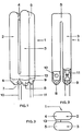
- Figure 1 shows a perspective view of a preferred embodiment of a compact low-pressure discharge lamp without a base
- FIG. 2 shows a side view of a lamp according to FIG. 1
- FIG. 3 shows a top view of a lamp according to FIG. 1
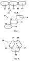
- FIG. 4 shows a plan view of a low-pressure discharge lamp without a base, in which the longitudinal tube sections of the different sections lie in planes which run parallel to one another
- FIG. 5 shows a plan view of a low-pressure discharge lamp without a base, in which the longitudinal tube sections of all sections lie in one plane
- FIG. 6 shows a plan view of a low-pressure discharge lamp without a base with an annular arrangement of the sections, the surface enveloping the longitudinal tube sections forming a cylinder with a polygonal cross section.
In Figur 1 bis 3 ist eine bevorzugte Ausführungsform des Entladungsgefäßes 1 der erfindungsgemäßen kompakten Niederdruckentladungslampe dargestellt. Das Entladungsgefäß 1 setzt sich im wesentlichen aus den beiden Teilstücken 2, 3 zusammen, die aus einem U-förmig gebogenen Glasrohr von 12 mm Außendurchmesser bestehen und jeweils zwei parallel im Abstand von 3 mm zueinander verlaufende Längsrohrabschnitte von 105 mm Länge aufweisen Die Ecken der U-förmigen Bögen der Teilstücke 2, 3 sind ausgeblasen, so daß die Querrohrabschnitte 4, 5 im wesentlichen senkrecht zu den Längsrohrabschnitten verlaufen. An den Enden sind die Teilstücke 2, 3 durch Quetschungen 6, 7, 8, 9 abgedichtet, wobei jeweils eine Quetschung 7, 9 jedes Teilstücks 2, 3 eine Elektrodenhalterung 10, 11 trägt.1 to 3 show a preferred embodiment of the
Beide Teilstücke 2, 3 sind in einer Flucht so hintereinander angeordnet, daß die beiden Längsrohrabschnitte der verschiedenen Teilstücke 2, 3 in jeweils parallel zueinander verlaufenden Ebenen liegen und sich die Quetschungen 7, 9 mit den Elektrodenhalterungen 10, 11 auf der gleichen Seite befinden. Mittels einer einen Durchlaß 12 bildenden Querverschmelzung 13 nahe den beiden Quetschungen 6, 8 ohne Elektrodenhalterungen sind die beiden Teilstücke 2, 3 so miteinander verbunden, daß ein einfach zusammenhängender Entladungs weg gebildet wird.Both
Die kompakte Niederdruckentladungslampe kann mit einem Schraub- oder einem Schnappsockel versehen sein, dessen hochgezogener Rand gleichzeitig die Querverschmelzung 13 abdeckt.The compact low-pressure discharge lamp can be provided with a screw or a snap base, the raised edge of which simultaneously covers the
Im Betrieb an einer Vorschaltdrossel mit einem cos ϕ von 0,34 erzeugt die oben aufgeführte Lampe bei einer Lampenspannung von 97 V, einem Lampenstrom von 150 mA und einer Leistungsaufnahme von 11,5 W einen Lichtstrom von 850 Im.When operated on a series choke with a cos ϕ of 0.34, the lamp listed above generates a luminous flux of 850 Im at a lamp voltage of 97 V, a lamp current of 150 mA and a power consumption of 11.5 W.
Bei einer Ausführungsform wie in Figur 4 dargestellt, sind die drei Teilstücke 14, 15, 16 des Entladungsgefäßes 17 ebenfalls so angeordnet, daß die beiden Längsrohrabschnitte der verschiedenen Teilstücke 14,15, 16 in jeweils parallel zueinander verlaufenden Ebenen liegen. Die Teilstücke 14, 15, 16 bilden hier jedoch keine einheitliche Fluchtlinie, sondern sind jeweils seitlich gegeneinander versetzt und durch Querverschmelzungen 18, 19 zu einem einheitlichen Entladungsweg verbunden.In an embodiment as shown in Figure 4, the three
In Figur 5 ist eine weitere Ausführungsform der erfindungsgemäßen Lampe dargestellt. Das Entladungsgefäß 20 besteht ebenfalls aus drei Teilstücken 21, 22, 23, die hier jedoch nebeneinander angeordnet sind, wobei die Längsrohrabschnitte aller Teilstücke 21, 22, 23 in einer Ebene liegen. Die Teilstücke 21, 22, 23 sind durch Querverschmelzungen 24, 25 verbunden, so daß ein einfach zusammenhängender flächenförmiger Entladungsweg gebildet wird.FIG. 5 shows a further embodiment of the lamp according to the invention. The
Es ist auch möglich, durch entsprechende Anordnung der Teilstücke dem Entladungsgefäß eine mehr ringförmige Form zu geben. In Figur 6 ist ein Entladungsgefäß 26 für eine kompakte Niederdruckentladungslampe dargestellt, bei der die Teilstücke 27, 28, 29 so angeordnet sind, daß die Ebenen, in denen die Längsrohrabschnitte jedes Teilstücks 27, 28, 29 liegen, im Schnitt ein gleichseitiges Dreieck bilden. Die Teilstücke 27, 28, 29 sind auch hier durch Querverschmelzungen 30, 31 zu einem einfach zusammenhängenden Entladungsgefäß verbunden.It is also possible to give the discharge vessel a more annular shape by arranging the sections accordingly. FIG. 6 shows a
Claims (5)
Applications Claiming Priority (2)
| Application Number | Priority Date | Filing Date | Title |
|---|---|---|---|
| DE8333920U | 1983-11-25 | ||
| DE19838333920U DE8333920U1 (en) | 1983-11-25 | 1983-11-25 | COMPACT LOW PRESSURE DISCHARGE LAMP |
Publications (3)
| Publication Number | Publication Date |
|---|---|
| EP0143419A2 EP0143419A2 (en) | 1985-06-05 |
| EP0143419A3 EP0143419A3 (en) | 1986-05-07 |
| EP0143419B1 true EP0143419B1 (en) | 1989-06-21 |
Family
ID=6759263
Family Applications (1)
| Application Number | Title | Priority Date | Filing Date |
|---|---|---|---|
| EP84113977A Expired EP0143419B1 (en) | 1983-11-25 | 1984-11-19 | Compact low-pressure discharge lamp |
Country Status (4)
| Country | Link |
|---|---|
| EP (1) | EP0143419B1 (en) |
| JP (3) | JPS60124345A (en) |
| DE (2) | DE8333920U1 (en) |
| HK (1) | HK91693A (en) |
Families Citing this family (10)
| Publication number | Priority date | Publication date | Assignee | Title |
|---|---|---|---|---|
| DE3741566C2 (en) * | 1987-12-08 | 1996-07-18 | Patent Treuhand Ges Fuer Elektrische Gluehlampen Mbh | Compact low pressure discharge lamp |
| NL8501340A (en) * | 1985-05-10 | 1986-12-01 | Philips Nv | LOW-PRESSURE MERCURY DISCHARGE LAMP. |
| FR2590725B1 (en) * | 1985-06-27 | 1988-06-17 | Elf Aquitaine | FLUORESCENT TUBE LAMP |
| JPS6276149A (en) * | 1985-09-28 | 1987-04-08 | Toshiba Corp | Fluorescent lamp |
| JPH07114111B2 (en) * | 1985-10-25 | 1995-12-06 | 東芝ライテック株式会社 | Method of manufacturing low pressure metal vapor discharge lamp |
| US4794301A (en) * | 1986-08-19 | 1988-12-27 | Kabushiki Kaisha Toshiba | Fluorescent lamp having a convoluted discharge passage and fluorescent lamp apparatus incorporating the same |
| SE457760B (en) * | 1987-03-23 | 1989-01-23 | Lumalampan Ab | PROCEDURES FOR THE PREPARATION OF COMPACT LIGHTS |
| JPH083997B2 (en) * | 1988-12-12 | 1996-01-17 | 東芝ライテック株式会社 | Low pressure mercury vapor discharge lamp |
| KR970046574U (en) * | 1995-12-21 | 1997-07-31 | Compact fluorescent lamps | |
| DE19613358C1 (en) * | 1996-04-03 | 1997-10-09 | Heraeus Noblelight Gmbh | Optical spotlight |
Family Cites Families (4)
| Publication number | Priority date | Publication date | Assignee | Title |
|---|---|---|---|---|
| NL185479C (en) * | 1979-04-03 | 1990-04-17 | Philips Nv | LOW PRESSURE GAS DISCHARGE LAMP. |
| DE3112878A1 (en) * | 1981-03-31 | 1982-10-14 | Patent-Treuhand-Gesellschaft für elektrische Glühlampen mbH, 8000 München | MERCURY VAPOR LOW-PRESSURE DISCHARGE LAMP AND METHOD FOR PRODUCING THE SAME |
| JPS58112238A (en) * | 1981-12-25 | 1983-07-04 | Toshiba Corp | Fluorescent lamp |
| JPS58112237A (en) * | 1981-12-25 | 1983-07-04 | Toshiba Corp | Fluorescent lamp |
-
1983
- 1983-11-25 DE DE19838333920U patent/DE8333920U1/en not_active Expired
-
1984
- 1984-11-15 JP JP59239618A patent/JPS60124345A/en active Pending
- 1984-11-19 DE DE8484113977T patent/DE3478777D1/en not_active Expired
- 1984-11-19 EP EP84113977A patent/EP0143419B1/en not_active Expired
-
1992
- 1992-08-06 JP JP055314U patent/JPH0623155U/en active Pending
-
1993
- 1993-09-02 HK HK916/93A patent/HK91693A/en not_active IP Right Cessation
-
1996
- 1996-07-26 JP JP1996007339U patent/JP2586587Y2/en not_active Expired - Lifetime
Also Published As
| Publication number | Publication date |
|---|---|
| EP0143419A3 (en) | 1986-05-07 |
| JPH0970U (en) | 1997-01-28 |
| JP2586587Y2 (en) | 1998-12-09 |
| EP0143419A2 (en) | 1985-06-05 |
| JPH0623155U (en) | 1994-03-25 |
| HK91693A (en) | 1993-09-10 |
| DE8333920U1 (en) | 1985-05-02 |
| JPS60124345A (en) | 1985-07-03 |
| DE3478777D1 (en) | 1989-07-27 |
Similar Documents
| Publication | Publication Date | Title |
|---|---|---|
| EP0061758B1 (en) | Low-pressure mercury vapour lamps and method for their manufacture | |
| DE2554781C2 (en) | Lamp bulb for a fluorescent lamp and process for its manufacture | |
| DE3106892A1 (en) | FLUORESCENT LAMP ARRANGEMENT AND METHOD FOR PRODUCING THE SAME | |
| EP0143419B1 (en) | Compact low-pressure discharge lamp | |
| DE3027536C2 (en) | ||
| DE3632810C2 (en) | ||
| DD245081A5 (en) | COMPACT MERCURY LOW-PRESSURE DAMPING DISCHARGE LAMP AND A METHOD OF MANUFACTURING THEREOF | |
| DD268329A5 (en) | METHOD FOR PRODUCING A COMPACT GAS DISCHARGE TUBE AND A COMPACT GAS DISCHARGE TUBE | |
| DE3005052A1 (en) | ELECTRIC DISCHARGE LAMPS | |
| DE3543986A1 (en) | HIGH PRESSURE DISCHARGE LAMP | |
| EP0758142A2 (en) | Halogen incandescent lamp | |
| DE2118061B2 (en) | Process for the manufacture of incandescent lamps | |
| DE4031117A1 (en) | High pressure discharge lamp and method for producing the lamp | |
| DE3802729C2 (en) | ||
| EP0220673B1 (en) | High-pressure discharge lamp | |
| EP0076503B1 (en) | One-base low-pressure discharge lamp, and method of manufacturing it | |
| DE3437212A1 (en) | Single-capped low-pressure discharge lamp | |
| EP0077077A2 (en) | Panel-shaped low-pressure mercury vapour discharge lamp | |
| DE3045090C2 (en) | U-shaped fluorescent lamp | |
| DE3344270A1 (en) | COMPACT LOW PRESSURE DISCHARGE LAMP | |
| EP0219860B1 (en) | Process for manufacturing a metal halide high-pressure discharge lamp having a single pinch, and a lamp manufactured according to this process | |
| EP0118100B1 (en) | Low-pressure discharge lamp with one-sided lamp base | |
| DE19647832A1 (en) | Compact folded tubular fluorescent lamp | |
| DE3439874A1 (en) | FLUORESCENT LAMP AND METHOD FOR THEIR PRODUCTION | |
| EP0219861A2 (en) | Process for manufacturing a metal halide high-pressure discharge lamp having a single pinch, and a lamp manufactured according to this process |
Legal Events
| Date | Code | Title | Description |
|---|---|---|---|
| PUAI | Public reference made under article 153(3) epc to a published international application that has entered the european phase |
Free format text: ORIGINAL CODE: 0009012 |
|
| AK | Designated contracting states |
Designated state(s): DE FR GB IT |
|
| PUAL | Search report despatched |
Free format text: ORIGINAL CODE: 0009013 |
|
| AK | Designated contracting states |
Kind code of ref document: A3 Designated state(s): DE FR GB IT |
|
| 17P | Request for examination filed |
Effective date: 19860321 |
|
| 17Q | First examination report despatched |
Effective date: 19871020 |
|
| GRAA | (expected) grant |
Free format text: ORIGINAL CODE: 0009210 |
|
| AK | Designated contracting states |
Kind code of ref document: B1 Designated state(s): DE FR GB IT |
|
| GBT | Gb: translation of ep patent filed (gb section 77(6)(a)/1977) | ||
| REF | Corresponds to: |
Ref document number: 3478777 Country of ref document: DE Date of ref document: 19890727 |
|
| ET | Fr: translation filed | ||
| ITF | It: translation for a ep patent filed |
Owner name: STUDIO JAUMANN |
|
| PLBI | Opposition filed |
Free format text: ORIGINAL CODE: 0009260 |
|
| 26 | Opposition filed |
Opponent name: LUMALAMPAN AKTIEBOLAG Effective date: 19900320 |
|
| ITTA | It: last paid annual fee | ||
| PLBN | Opposition rejected |
Free format text: ORIGINAL CODE: 0009273 |
|
| STAA | Information on the status of an ep patent application or granted ep patent |
Free format text: STATUS: OPPOSITION REJECTED |
|
| 27O | Opposition rejected |
Effective date: 19931017 |
|
| REG | Reference to a national code |
Ref country code: GB Ref legal event code: IF02 |
|
| PGFP | Annual fee paid to national office [announced via postgrant information from national office to epo] |
Ref country code: GB Payment date: 20031104 Year of fee payment: 20 |
|
| PGFP | Annual fee paid to national office [announced via postgrant information from national office to epo] |
Ref country code: FR Payment date: 20031127 Year of fee payment: 20 |
|
| PGFP | Annual fee paid to national office [announced via postgrant information from national office to epo] |
Ref country code: DE Payment date: 20040119 Year of fee payment: 20 |
|
| PG25 | Lapsed in a contracting state [announced via postgrant information from national office to epo] |
Ref country code: GB Free format text: LAPSE BECAUSE OF EXPIRATION OF PROTECTION Effective date: 20041118 |
|
| REG | Reference to a national code |
Ref country code: GB Ref legal event code: PE20 |
|
| APAH | Appeal reference modified |
Free format text: ORIGINAL CODE: EPIDOSCREFNO |