EP0143145A2 - Rack for storing lacquer tins - Google Patents
Rack for storing lacquer tins Download PDFInfo
- Publication number
- EP0143145A2 EP0143145A2 EP84103215A EP84103215A EP0143145A2 EP 0143145 A2 EP0143145 A2 EP 0143145A2 EP 84103215 A EP84103215 A EP 84103215A EP 84103215 A EP84103215 A EP 84103215A EP 0143145 A2 EP0143145 A2 EP 0143145A2
- Authority
- EP
- European Patent Office
- Prior art keywords
- paint
- guide housing
- shaped guide
- drive
- base
- Prior art date
- Legal status (The legal status is an assumption and is not a legal conclusion. Google has not performed a legal analysis and makes no representation as to the accuracy of the status listed.)
- Granted
Links
Images


Classifications
-
- B—PERFORMING OPERATIONS; TRANSPORTING
- B44—DECORATIVE ARTS
- B44D—PAINTING OR ARTISTIC DRAWING, NOT OTHERWISE PROVIDED FOR; PRESERVING PAINTINGS; SURFACE TREATMENT TO OBTAIN SPECIAL ARTISTIC SURFACE EFFECTS OR FINISHES
- B44D3/00—Accessories or implements for use in connection with painting or artistic drawing, not otherwise provided for; Methods or devices for colour determination, selection, or synthesis, e.g. use of colour tables
- B44D3/06—Implements for stirring or mixing paints
-
- B—PERFORMING OPERATIONS; TRANSPORTING
- B01—PHYSICAL OR CHEMICAL PROCESSES OR APPARATUS IN GENERAL
- B01F—MIXING, e.g. DISSOLVING, EMULSIFYING OR DISPERSING
- B01F27/00—Mixers with rotary stirring devices in fixed receptacles; Kneaders
- B01F27/80—Mixers with rotary stirring devices in fixed receptacles; Kneaders with stirrers rotating about a substantially vertical axis
- B01F27/88—Mixers with rotary stirring devices in fixed receptacles; Kneaders with stirrers rotating about a substantially vertical axis with a separate receptacle-stirrer unit that is adapted to be coupled to a drive mechanism
-
- B—PERFORMING OPERATIONS; TRANSPORTING
- B01—PHYSICAL OR CHEMICAL PROCESSES OR APPARATUS IN GENERAL
- B01F—MIXING, e.g. DISSOLVING, EMULSIFYING OR DISPERSING
- B01F35/00—Accessories for mixers; Auxiliary operations or auxiliary devices; Parts or details of general application
- B01F35/30—Driving arrangements; Transmissions; Couplings; Brakes
- B01F35/32—Driving arrangements
- B01F35/323—Driving arrangements for vertical stirrer shafts
- B01F35/3231—Driving several stirrer shafts, e.g. about the same axis
-
- B—PERFORMING OPERATIONS; TRANSPORTING
- B01—PHYSICAL OR CHEMICAL PROCESSES OR APPARATUS IN GENERAL
- B01F—MIXING, e.g. DISSOLVING, EMULSIFYING OR DISPERSING
- B01F35/00—Accessories for mixers; Auxiliary operations or auxiliary devices; Parts or details of general application
- B01F35/40—Mounting or supporting mixing devices or receptacles; Clamping or holding arrangements therefor
- B01F35/42—Clamping or holding arrangements for mounting receptacles on mixing devices
-
- B—PERFORMING OPERATIONS; TRANSPORTING
- B65—CONVEYING; PACKING; STORING; HANDLING THIN OR FILAMENTARY MATERIAL
- B65G—TRANSPORT OR STORAGE DEVICES, e.g. CONVEYORS FOR LOADING OR TIPPING, SHOP CONVEYOR SYSTEMS OR PNEUMATIC TUBE CONVEYORS
- B65G1/00—Storing articles, individually or in orderly arrangement, in warehouses or magazines
- B65G1/02—Storage devices
Definitions
- the invention relates to a shelf and paint cans for inclusion in the shelf.
- the shelf consists of side vertical brackets and support plates extending between the supports at different vertical distances and a drive device with a drive motor and a drive transmission on each support plate to a series of first drive members on one side of each support plate, each for engagement with a second drive member is formed on a paint can.
- the paint can for inclusion in the shelf contains a lid in which a stirrer shaft is mounted, which carries an agitator on the inside of the lid and a second drive member on the outside of the lid.
- the lid is provided with a closure member for a pouring opening and with an opening lever which can be actuated against the force of a spring in the opening sense for the closure member.
- the support plates made of sheet steel and according to the dimensions of the various paint cans are arranged at different distances from one another on the supports.
- the drive transmission takes place by means of V-belts in the support plates, through which drive shafts extend downward, at the ends of which first drive members are pivotally arranged in the form of plates which extend downward on opposite sides of the drive shaft.
- the drive shafts and the first drive elements are arranged at a distance from one another which is determined by the diameter of the paint cans which are placed on the next lower support plate.
- Each paint can is sealed with a removable lid, on which a pouring opening can be closed by a spring-loaded closure member and in which a stirrer shaft is rotatably mounted.
- a second drive member is arranged in the form of a fork with upstanding ends adapted to the first drive member.
- the plates grip the upstanding ends of the fork and take them with them, so that the stirrer shaft is rotated. This rotation is necessary to ensure the homogeneity of the paint contained in the can over a long period of time.
- the drive elements which bring about the drive connection between the V-belt in the support plates and the agitators inside the paint cans, are freely accessible during operation, which is a considerable disadvantage for the occupational safety of these shelves.
- the paint cans can be moved freely on the support plates, so that when the paint can is placed on the shelf, it is not readily possible to achieve a perfect alignment between the first and second drive members and thus trouble-free power transmission.
- the object of the invention is to provide a shelf for paint cans of the type mentioned, which offers a high level of work and operational safety.
- this object is achieved in that on the side of the support plate from which the first drive members protrude, generally U-shaped guide housings are arranged for each one paint can, each of which encloses the first drive member.
- the inclusion of the drive members in the guide housing makes the drive connection and its moving parts inaccessible to external intervention. At the same time, the great advantage is achieved by the guide housing that the paint cans are guided into the shelf when they are set and that the drive elements of the drive connection are always perfectly aligned with one another.
- the U-shaped guide housing is preferably formed with a guide part which determines the position of the paint can on the shelf and a starting from the base of the U-shaped guide housing and at a distance from the edges of the side walls of the U- facing away from the support plate.
- shaped guide housing extending guide plate with a central and towards the base of the guide housing guide slot.
- each U-shaped guide housing also contains a latching element which extends on a side facing away from the base and at a distance from the protective wall between the side walls.
- the latch holds the paint can in a position in which the first and second drive elements are engaged.
- the aforementioned object is achieved in that a generally U-shaped guide member projecting from the outside of the lid is provided and a latching device is arranged on the opening lever.
- the base of the U-shaped guide member is advantageously arranged on the cover and the legs of the U-shaped guide member form guide elements that interact with the guide housing on the support plate.
- the latching device is preferably arranged on the side of the opening lever facing away from the cover and can form a latching member which projects from the opening lever and which cooperates with the latching element on the guide housing in order to drive the paint can in it secure aligned position.
- Such a design of the paint can achieves extensive and thus particularly effective guidance even with large-volume paint cans.
- the formation of the locking member on the opening lever enables the locking in the operating position against the spring of the opening lever, so that the paint can can only be removed from its operating position by actuating the opening lever and thus not inadvertently.
- side supports 1 and 2 can be seen, which are connected at the bottom by a base plate 3 and at the top by a cross member 4.
- the bottom plate 3 can, if necessary extend even further forward and the supports 1, 2 can optionally be provided with correspondingly projecting side parts; A table can be built over this part of the base plate.
- the cross member 4 can be provided with a lamp for illuminating the shelf.
- the supports 1 and 2, the base plate 3 and the cross member 4 can be made of any suitable material and are preferably made of sheet steel.
- rows of paint cans 41 of different sizes can be arranged standing on the support plates 5 of the shelf.
- further support plates for holding paint cans 41 can also be arranged under the table, if present.
- a control box 10 for a main drive motor in the form of an electric motor is attached to the carrier 1;
- a main drive shaft extends over the height of the carrier 1 and is in drive connection with the electric motor.
- drive disks for drive transmission to first drive members 11 are arranged on the main drive shaft by means of V-belts.
- the generally U-shaped guide housing 20 consist of two side walls 22 which are arranged parallel to one another and at a distance from one another such that they enclose the first drive member 11 between them.
- the side walls 22 are connected by a semicircular base 23. From the free ends of the side walls 22, laterally angled insertion members 24 extend (see FIG. 3) so far down that they force the paint cans 41 to run.
- a guide plate 26 extends from the base 23 with a guide slot 27. This guide slot 27 is arranged and designed such that it receives the stirrer shaft 42 protruding from the cover 40 of a paint can 41 when a paint can 41 is inserted into the guide housing 20.
- a protective wall 28 extends between the side walls 22, so that the first drive member 11 is enclosed between the base 23 and the protective wall 28.
- a slot with a stop 29 is formed on each side, on which the guide member described below, located on the outside of the lid of the paint can, rests when the paint can is in its operating position.
- a fastening part 30 runs close to the insertion members 24 and connects the edges of the opposite side walls 22 to one another and serves to fasten the U-shaped guide housing 20 to the support plate 5.
- a locking element 31 runs underneath the fastening part 30 between the side walls 22 of the U-shaped guide housing 20.
- This locking element 31 can form a cylindrical rod or pin and be arranged and designed so that it interacts with a correspondingly formed on the cover 40 of a paint can 41 and arranged locking member, as described below.
- the locking element 31 can also be provided with a projection directed towards one side or can also form a sprue or a bolt secured with a nut.
- the fastening part 30 forms a web, on the lower edge of which the latching element 31 is attached in the form of an adapter sleeve.
- the U-shaped guide housing 20 are arranged on the support plates 5 in such a way that there is only a small lateral distance between the insertion members 24 of adjacent guide housing 20. In this way, the correct insertion of the paint can 41 into the respective guide housing 20 is ensured by the insertion members 24, the correct positioning being ensured by the stops 29 and the latching element 31.
- a lid 40 and a paint can 41 are shown in different views.
- a stirrer shaft 42 is rotatably mounted in the usual manner, which carries an agitator (not shown) on the inside of the cover 40 and a second drive member 44 on the outside of the cover 40.
- the lid 40 is provided with a pouring opening 45 which is closed by a closure member 46 which can be actuated by a spring-loaded opening lever 47.
- a generally U-shaped guide member 48 which projects from its outside and is fastened with its base to the cover 40 and its leg 49 form laterally offset guide elements 50 at the ends.
- the guide elements 50 on the cover 40 are designed and arranged such that they come to rest on the side walls 22 and the stops 29 of the U-shaped guide housing 20.
- a locking member 51 protrudes upward from the opening lever 47 and forms an inclined surface 52 on the side facing the second drive member 44.
- the locking member 51 is dimensioned and arranged such that it interacts with the locking element 31 on the guide housing 20.
- the cover 40 is provided with conventionally designed conical surfaces and clamping members 53 for the sealing closure of the paint can 41 and with a handle 54.
- the paint can 41 is pushed into the guide housing 20 by means of the handle 54 in such a way that the guide elements 50 come to rest on the side walls 22.
- the paint can 41 is then positioned on the relevant support plate 5 without first having a drive connection to the stirrer shaft 42.
- the locking member 51 must first be moved with its inclined surface 52 past the locking element 31, which is possible in that the spring-loaded opening lever 47 is briefly opened against the force of its spring.
- the paint can 41 is then pushed so far into the guide housing 20 that the front edges of the guide elements 50 on the paint can 41 rest against the stops 29 of the guide housing 20.
- the first and second drive members 11 and 44 are thereby brought into drive connection.
- the drive members 11, 44 are in the installed state of the paint can 41 between the side walls 22 of the U-shaped guide housing 20 and the guide elements 50 of the guide member 48 on the cover 40 of the paint can 41.
- the drive members 11, 44 are between the base 23 and the protective wall 28 of the U-shaped guide housing 20, which is arranged close to the support plate 5. The drive elements are thereby protected against external interference, and a particularly high level of work safety is achieved, since the rotating drive elements 11 and 44 are practically inaccessible during operation.
Landscapes
- Chemical & Material Sciences (AREA)
- Chemical Kinetics & Catalysis (AREA)
- Engineering & Computer Science (AREA)
- Mechanical Engineering (AREA)
- Coating Apparatus (AREA)
Abstract
Description
Die Erfindung betrifft ein Regal und Lackdosen zur Aufnahme in dem Regal.The invention relates to a shelf and paint cans for inclusion in the shelf.
Das Regal besteht aus seitlichen vertikalen Trägern und zwischen den Trägern in unterschiedlichen vertikalen Abständen verlaufenden Tragplatten und aus einer Antriebseinrichtung mit einem Antriebsmotor und einer Antriebsübertragung an jeder Tragplatte zu einer Reihe von ersten Antriebsgliedern an einer Seite jeder Tragplatte, deren jedes zum Eingriff mit einem zweiten Antriebsglied an einer Lackdose ausgebildet ist.The shelf consists of side vertical brackets and support plates extending between the supports at different vertical distances and a drive device with a drive motor and a drive transmission on each support plate to a series of first drive members on one side of each support plate, each for engagement with a second drive member is formed on a paint can.
Die Lackdose zur Aufnahme in dem Regal enthält einen Deckel, in dem eine Rührerwelle gelagert ist, die auf der Innenseite des Deckels ein Rührwerk und auf der Außenseite des Deckels ein zweites Antriebsglied trägt. Der Deckel ist mit einem Verschlußglied für eine Ausgießöffnung und mit einem gegen die Kraft einer Feder im öffnenden Sinne betätigbaren Öffnungshebel für das Verschlußglied versehen.The paint can for inclusion in the shelf contains a lid in which a stirrer shaft is mounted, which carries an agitator on the inside of the lid and a second drive member on the outside of the lid. The lid is provided with a closure member for a pouring opening and with an opening lever which can be actuated against the force of a spring in the opening sense for the closure member.
Bei einem bekannten Regal dieser Art sind die Tragplatten aus Stahlblech und entsprechend den Abmessungen der verschiedenen Lackdosen in verschiedenen Abständen voneinander an den Trägern angeordnet. Die Antriebsübertragung erfolgt durch Keilriemen in den Tragplatten, durch die sich nach unten Antriebswellen erstrecken, an deren Enden erste Antriebsglieder in Form von Platten schwenkbar angeordnet sind, die sich zu gegenüberliegenden Seiten der Antriebswelle nach unten erstrecken. Die Antriebswellen und die ersten Antriebsglieder sind in einem Abstand voneinander angeordnet, der durch den Durchmesser der Lackdosen bestimmt ist, die auf der nächstunteren Tragplatte abgestellt werden. Jede Lackdose ist mit einem abnehmbaren Deckel abdichtend verschlossen, an dem eine Ausgießöffnung durch ein federbelastetes Verschlußglied verschließbar ist und in dem eine Rührerwelle drehbar gelagert ist. Am Außenende der Rührerwelle ist ein zweites Antriebsglied in Form einer an das erste Antriebsglied angepaßten Gabel mit hochstehenden Enden angeordnet. Bei Inbetriebnahme der Antriebseinrichtung greifen die Platten an den hochstehenden Enden der Gabel an und nehmen diese mit, so daß die Rührerwelle in Drehung versetzt wird. Diese Drehung ist erforderlich, um auch über längere Zeit die Homogenität des in der Dose enthaltenen Lacks sicherzustellen.In a known shelf of this type, the support plates made of sheet steel and according to the dimensions of the various paint cans are arranged at different distances from one another on the supports. The drive transmission takes place by means of V-belts in the support plates, through which drive shafts extend downward, at the ends of which first drive members are pivotally arranged in the form of plates which extend downward on opposite sides of the drive shaft. The drive shafts and the first drive elements are arranged at a distance from one another which is determined by the diameter of the paint cans which are placed on the next lower support plate. Each paint can is sealed with a removable lid, on which a pouring opening can be closed by a spring-loaded closure member and in which a stirrer shaft is rotatably mounted. At the outer end of the stirrer shaft, a second drive member is arranged in the form of a fork with upstanding ends adapted to the first drive member. When the drive device is started up, the plates grip the upstanding ends of the fork and take them with them, so that the stirrer shaft is rotated. This rotation is necessary to ensure the homogeneity of the paint contained in the can over a long period of time.
Bei dem bekannten Regal sind die Antriebsglieder, welche die Antriebsverbindung zwischen dem Keilriemen in den Tragplatten und den Rührwerken im Inneren der Lackdosen bewirken, während des Betriebs frei zugänglich, was von erheblichem Nachteil für die Arbeitssicherheit dieser Regale ist. Außerdem sind die Lackdosen auf den Tragplatten frei verschiebbar, so daß beim Einstellen der Lackdose in das Regal nicht ohne weiteres eine einwandfreie Ausrichtung zwischen den ersten und zweiten Antriebsgliedern und damit eine störungsfreie Kraftübertragung gegeben ist.In the known shelf, the drive elements, which bring about the drive connection between the V-belt in the support plates and the agitators inside the paint cans, are freely accessible during operation, which is a considerable disadvantage for the occupational safety of these shelves. In addition, the paint cans can be moved freely on the support plates, so that when the paint can is placed on the shelf, it is not readily possible to achieve a perfect alignment between the first and second drive members and thus trouble-free power transmission.
Dementsprechend besteht die Aufgabe der Erfindung darin, ein Regal für Lackdosen der eingangs genannten Art zu schaffen, das eine hohe Arbeits- und Betriebssicherheit bietet.Accordingly, the object of the invention is to provide a shelf for paint cans of the type mentioned, which offers a high level of work and operational safety.
Erfindungsgemäß wird diese Aufgabe dadurch gelöst, daß an der Seite der Tragplatte, von der die ersten Antriebsglieder vorstehen, allgemein U-förmige Führungsgehäuse für jeweils eine Lackdose angeordnet sind, deren jedes das erste Antriebsglied umschließt.According to the invention this object is achieved in that on the side of the support plate from which the first drive members protrude, generally U-shaped guide housings are arranged for each one paint can, each of which encloses the first drive member.
Der Einschluß der Antriebsglieder in das Führungsgehäuse macht die Antriebsverbindung und deren bewegliche Teile für Eingriffe von außen unzugänglich. Gleichzeitig wird durch das Führungsgehäuse der große Vorteil erreicht, daß die Lackdosen beim Einstellen in das Regal geführt werden und dadurch die Antriebsglieder der Antriebsverbindung stets einwandfrei zueinander ausgerichtet sind.The inclusion of the drive members in the guide housing makes the drive connection and its moving parts inaccessible to external intervention. At the same time, the great advantage is achieved by the guide housing that the paint cans are guided into the shelf when they are set and that the drive elements of the drive connection are always perfectly aligned with one another.
Vorteilhafterweise erstreckt sich zwischen Seitenwänden des Führungsgehäuses eine dessen Basis gegenüberliegende Schutzwand, und das erste Antriebsglied ist zwischen der Basis und der Schutzwand eingeschlossen. Vorzugsweise ist das U-förmige Führungsgehäuse bei dem erfindungsgemäßen Regal mit einem Führungsteil ausgebildet, das die Position der Lackdose am Regal bestimmt und eine von der Basis des U-förmigen Führungsgehäuses ausgehende, in einem Abstand von den der Tragplatte abgekehrten Kanten der Seitenwände des U-förmigen Führungsgehäuses verlaufende Führungsplatte mit einem mittigen und zur Basis des Führungsgehäuses gerichteten Führungsschlitz enthalten kann.A protective wall opposite the base of the guide housing advantageously extends between the side walls of the guide housing, and the first drive member is enclosed between the base and the protective wall. In the shelf according to the invention, the U-shaped guide housing is preferably formed with a guide part which determines the position of the paint can on the shelf and a starting from the base of the U-shaped guide housing and at a distance from the edges of the side walls of the U- facing away from the support plate. shaped guide housing extending guide plate with a central and towards the base of the guide housing guide slot.
Vorzugsweise enthält bei dem Regal nach der Erfindung jedes U-förmige Führungsgehäuse weiterhin ein Rastelement, das sich an einer von der Basis abgekehrten Seite im Abstand von der Schutzwand zwischen den Seitenwänden erstreckt. Durch die Einrastung wird die Lackdose in einer Stellung festgehalten, in der die ersten und zweiten Antriebsglieder im Eingriff sind.Preferably, in the shelf according to the invention, each U-shaped guide housing also contains a latching element which extends on a side facing away from the base and at a distance from the protective wall between the side walls. The latch holds the paint can in a position in which the first and second drive elements are engaged.
Hinsichtlich der Lackdose nach der Erfindung wird die vorgenannte Aufgabe dadurch gelöst, daß ein allgemein U-förmiges, von der Außenseite des Deckels aufragendes Führungsglied vorgesehen und an dem Öffnungshebel eine Rastvorrichtung angeordnet ist.With regard to the paint can according to the invention, the aforementioned object is achieved in that a generally U-shaped guide member projecting from the outside of the lid is provided and a latching device is arranged on the opening lever.
Vorteilhafterweise ist dabei die Basis des U-förmigen Führungsglieds an dem Deckel angeordnet und die Schenkel des U-förmigen Führungsglieds bilden mit dem Führungsgehäuse an der Tragplatte zusammenwirkende Führungselemente.The base of the U-shaped guide member is advantageously arranged on the cover and the legs of the U-shaped guide member form guide elements that interact with the guide housing on the support plate.
Vorzugsweise ist die Rastvorrichtung an der dem Deckel abgewandten Seite des Öffnungshebels angeordnet und kann ein von dem Öffnungshebel aufragenden Rastglied bilden, das mit dem Rastelement an dem Führungsgehäuse zusammenwirkt, um die Lackdose in ihrer zum Antrieb ausgerichteten Stellung zu sichern.The latching device is preferably arranged on the side of the opening lever facing away from the cover and can form a latching member which projects from the opening lever and which cooperates with the latching element on the guide housing in order to drive the paint can in it secure aligned position.
Durch eine solche Ausbildung der Lackdose wird eine flächenhafte und damit besonders wirksame Führung auch bei großvolumigen Lackdosen erreicht. Die Ausbildung des Rastgliedes am Öffnungshebel ermöglicht die Einrastung in der Betriebsstellung gegen die Feder des Öffnungshebels, so daß die Lackdose nur unter Betätigung des Öffnungshebels und damit nicht unbeabsichtigt aus ihrer Betriebsstellung entnommen werden kann.Such a design of the paint can achieves extensive and thus particularly effective guidance even with large-volume paint cans. The formation of the locking member on the opening lever enables the locking in the operating position against the spring of the opening lever, so that the paint can can only be removed from its operating position by actuating the opening lever and thus not inadvertently.
Ein Ausführungsbeispiel der Erfindung ist in den Abbildungen dargestellt und wird nachfolgend anhand der Bezugszeichen im einzelnen erläutert und beschrieben. Es zeigen:
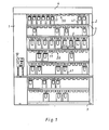
- Fig. 1 eine Vorderansicht des Regals nach der Erfindung mit einigen Lackdosen;
- Fig. 2 eine Draufsicht auf ein Führungsgehäuse an der Unterseite der Tragplatte in dem Regal nach Fig. 1;
- Fig. 3 eine Vorderansicht der Rasthalterung nach Fig. 2;
- Fig. 4 eine Seitenansicht einer Lackdose mit Deckel in dem Regal nach Fig. 1; und
- Fig. 5 eine Rückansicht der Lackdose mit Deckel nach Fig. 4.
- Figure 1 is a front view of the shelf according to the invention with some paint cans.
- Figure 2 is a plan view of a guide housing on the underside of the support plate in the shelf of Fig. 1.
- Fig. 3 is a front view of the locking bracket according to Fig. 2;
- Fig. 4 is a side view of a paint can with a lid in the shelf of Fig. 1; and
- 5 is a rear view of the paint can with lid of FIG. 4th
In der Vorderansicht des Regals nach Fig. 1 erkennt man seitliche Träger 1 und 2, die unten durch eine Bodenplatte 3 und oben durch einen Querträger 4 verbunden sind. Die Bodenplatte 3 kann sich gegebenenfalls auch noch weiter nach vorn erstrecken und die Träger 1, 2 können ggfs. mit entsprechend nach vorn vorstehenden Seitenteilen versehen sein; über diesem Teil der Bodenplatte kann ein Tisch errichtet werden. Der Querträger 4 kann mit einer Lampe zur Beleuchtung des Regals versehen werden. Die Träger 1 und 2, die Bodenplatte 3 und der Querträger 4 können aus jedem geeigneten Material bestehen und sind vorzugsweise aus Stahlblech gefertigt.1, side supports 1 and 2 can be seen, which are connected at the bottom by a
Zwischen den Trägern 1 und 2 erstrecken sich eine Reihe von Tragplatten 5, die vertikal in Abständen voneinander angeordnet sind, die durch die Höhe der jeweiligen Lackdosen 41 bestimmt sind. An der Unterseite der Tragplatten 5 befinden sich Führungsgehäuse 20, die in horizontalen Abständen voneinander angeordnet sind, die an die Durchmesser der jeweiligen Lackdosen 41 angepaßt sind. Auf diese Weise lassen sich auf den Tragplatten 5 des Regals Reihen von Lackdosen 41 verschiedener Größe stehend anordnen. In entsprechender Weise können auch unter dem ggfs. vorhandenen Tisch weitere Tragplatten zur Halterung von Lackdosen 41 angeordnet werden. In Fig. 1 erkennt man weiterhin an den Tragplatten 5 angeordnete Untersätze 6, die an den Tragplatten 5 verschiebbar angeordnet sind und ermöglichen, daß die jeweils kleineren Lackdosen 41 auf allen Tragplatten 5 angebracht werden können.Between the
An dem Träger 1 ist ein Steuerkasten 10 für einen Hauptantriebsmotor in Gestalt eines Elektromotors befestigt; über die Höhe des Trägers 1 erstreckt sich eine Hauptantriebswelle, die mit dem Elektromotor in Antriebsverbindung steht. In Höhe der Tragplatten 5 sind an der Hauptantriebswelle Antriebsscheiben zur Antriebsübertragung auf erste Antriebsglieder 11 durch Keilriemen angeordnet.A
Die allgemein U-förmigen Führungsgehäuse 20 bestehen aus zwei Seitenwänden 22, die parallel zueinander und in einem Abstand voneinander so angeordnet sind, daß sie das erste Antriebsglied 11 zwischen sich einschließen. Die Seitenwände 22 sind durch eine halbkreisförmig ausgebildete Basis 23 verbunden. Von den freien Enden der Seitenwände 22 erstrecken sich seitlich abgewinkelte Einführungsglieder 24, die (vgl. Fig. 3) so weit nach unten verlaufen, daß sie eine Zwangsführung der Lackdosen 41 bewirken. Von der Basis 23 erstreckt sich eine Führungsplatte 26 mit einem Führungsschlitz 27. Dieser Führungsschlitz 27 ist so angeordnet und ausgebildet, daß er die von dem Deckel 40 einer Lackdose 41 vorstehende Rührerwelle 42 aufnimmt, wenn eine Lackdose 41 in das Führungsgehäuse 20 eingeschoben wird. An der der Basis 23 gegenüberliegenden Seite des ersten Antriebsglieds 11 verläuft zwischen den Seitenwänden 22 eine Schutzwand 28, so daß das erste Antriebsglied 11 zwischen der Basis 23 und der Schutzwand 28 eingeschlossen ist. Zwischen der Führungsplatte 26 und den Seitenwänden 22 des Führungsgehäuses 20 ist auf jeder Seite ein Schlitz mit einem Anschlag 29 ausgebildet, an dem das weiter unten beschriebene, an der Außenseite des Deckels der Lackdose befindliche Führungsglied anliegt, wenn die Lackdose ihre Betriebsstellung einnimmt.The generally U-shaped
Nahe den Einführungsgliedern 24 verläuft ein Befestigungsteil 30, das die Kanten der gegenüberliegenden Seitenwände 22 miteinander verbindet und zur Befestigung des U-förmigen Führungsgehäuses 20 an der Tragplatte 5 dient.A fastening
Ferner verläuft zwischen den Seitenwänden 22 des U-förmigen Führungsgehäuses 20 ein Rastelement 31 unterhalb des Befestigungsteils 30. Dieses Rastelement 31 kann einen zylindrischen Stab oder Stift bilden und so angeordnet und ausgebildet sein, daß es mit einem entsprechend am Deckel 40 einer Lackdose 41 ausgebildeten und angeordneten Rastglied zusammenwirkt, wie weiter unten beschrieben ist. Das Rastelement 31 kann auch mit einem nach einer Seite gerichteten Vorsprung versehen sein oder auch einen Anguß oder einen mit einer Mutter gesicherten Bolzen bilden. In dem dargestellten Ausführungsbeispiel bildet das Befestigungsteil 30 einen Steg, an dessen Unterkante das Rastelement 31 in Form einer Spannhülse angebracht ist.Furthermore, a
Die U-förmigen Führungsgehäuse 20 werden an den Tragplatten 5 in der Weise angeordnet, daß nur ein geringer seitlicher Abstand zwischen den Einführungsgliedern 24 benachbarter Führungsgehäuse 20 besteht. Auf diese Weise wird durch die Einführungsglieder 24 die richtige Einführung der Lackdose 41 in das jeweilige Führungsgehäuse 20 sichergestellt, wobei die korrekte Positionierung durch die Anschläge 29 und das Rastelement 31 gewährleistet wird.The U-shaped
In Fig. 4 und 5 sind ein Deckel 40 und eine Lackdose 41 in verschiedenen Ansichten dargestellt. In diesem Deckel 40 ist in üblicher Weise eine Rührerwelle 42 drehbar gelagert, die an der Innenseite des Deckels 40 ein nicht dargestelltes Rührwerk und an der Außenseite des Deckels 40 ein zweites Antriebsglied 44 trägt. Der Deckel 40 ist mit einer Ausgießöffnung 45 versehen, die durch ein Verschlußglied 46, das mit einem federbelasteten Öffnungshebel 47 betätigbar ist, verschlossen ist. An dem Deckel 40 ist ferner ein von seiner Außenseite aufragendes, allgemein U-förmiges Führungsglied 48 angeordnet, das mit seiner Basis an dem Deckel 40 befestigt ist und dessen Schenkel 49 jeweils an den Enden seitlich versetzte Führungselemente 50 bilden. Die Führungselemente 50 an dem Deckel 40 sind so ausgebildet und angeordnet, daß sie an den Seitenwänden 22 und den Anschlägen 29 der U-förmigen Führungsgehäuse 20 zur Anlage kommen. Von dem Öffnungshebel 47 steht ein Rastglied 51 nach oben vor und bildet an der dem zweiten Antriebsglied 44 zugekehrten Seite eine Schrägfläche 52. Das Rastglied 51 ist so bemessen und angeordnet, daß es mit dem Rastelement 31 an dem Führungsgehäuse 20 zusammenwirkt. Schließlich ist der Deckel 40 mit konventionell ausgebildeten Kegelflächen und Klemmgliedern 53 zum abdichtenden Verschluß der Lackdose 41 und mit einem Handgriff 54 versehen.4 and 5, a
Zum Einsetzen der Lackdose 41 in das Regal wird die Lackdose 41 mittels des Handgriffs 54 so in das Führungsgehäuse 20 eingeschoben, daß die Führungselemente 50 an den Seitenwänden 22 zur Anlage kommen. Die Lackdose 41 ist dann an der betreffenden Tragplatte 5 positioniert, ohne daß zunächst eine Antriebsverbindung zur Rührerwelle 42 besteht. Dazu muß das Rastglied 51 erst mit seiner Schrägfläche 52 an dem Rastelement 31 vorbeibewegt werden, was dadurch möglich ist, daß der federbelastete Öffnungshebel 47 kurzfristig gegen die Kraft seiner Feder geöffnet wird. Die Lackdose 41 wird dann so weit in das Führungsgehäuse 20 eingeschoben, daß die Vorderkanten der Führungselemente 50 an der Lackdose 41 an den Anschlägen 29 des Führungsgehäuses 20 anliegen. Die ersten und zweiten Antriebsglieder 11 und 44 werden dadurch in Antriebsverbindung gebracht. Diese Verbindung ist nicht ohne weiteres wieder zu lösen, da das Rastglied 51 und das Rastelement 31 dem entgegenstehen. Es wird daher auf diese Weise eine sichere und genau reproduzierbare Positionierung der Lackdose 41 an der Tragplatte 5 hergestellt. Die Antriebsverbindung kann dadurch wieder gelöst werden, daß der Öffnungshebel 47 gegen die Kraft seiner Feder geöffnet wird, wodurch die Lackdose 41 aus dem Führungsgehäuse 20 herausgezogen und das Rastglied 51 außer Rasteingriff mit dem Rastelement 31 gebracht werden kann.To insert the paint can 41 into the shelf, the paint can 41 is pushed into the
Bei dem Regal befinden sich die Antriebsglieder 11, 44 im eingebauten Zustand der Lackdose 41 zwischen den Seitenwänden 22 des U-förmigen Führungsgehäuses 20 und den Führungselementen 50 des Führungsglieds 48 am Deckel 40 der Lackdose 41. Zusätzlich sind die Antriebsglieder 11, 44 zwischen der Basis 23 und der Schutzwand 28 des U-förmigen Führungsgehäuses 20 eingeschlossen, das dicht an der Tragplatte 5 angeordnet ist. Die Antriebsglieder sind dadurch gegen Eingriffe von außen geschützt, und es wird eine besonders hohe Arbeitssicherheit erreicht, da die umlaufenden Antriebsglieder 11 und 44 während des Betriebs praktisch unzugänglich sind.In the shelf, the
Claims (15)
dadurch gekennzeichnet, daß ein allgemein U-förmiges, von der Außenseite des Deckels (40) aufragendes Führungsglied (48) vorgesehen und an dem Öffnungshebel (47) eine Rastvorrichtung angeordnet ist.11. Paint can for inclusion in a shelf according to one of claims 1 to 10, with a lid (40) in which a stirrer shaft is mounted, a stirrer on the inside of the lid (40) and on the outside of the lid (40) carries a second drive member (44) with a closure member (46) for a pouring opening (45) and an opening lever (47) for the closure member (46) which can be actuated against the force of a spring in the opening sense,
characterized in that a generally U-shaped guide member (48) projecting from the outside of the cover (40) is provided and a latching device is arranged on the opening lever (47).
Priority Applications (1)
| Application Number | Priority Date | Filing Date | Title |
|---|---|---|---|
| AT84103215T ATE29862T1 (en) | 1983-11-26 | 1984-03-23 | SHELF FOR PAINT CANS. |
Applications Claiming Priority (4)
| Application Number | Priority Date | Filing Date | Title |
|---|---|---|---|
| DE19838334015 DE8334015U1 (en) | 1983-11-26 | 1983-11-26 | SHELVES FOR RECORDING PAINT CAN |
| DE8334016U DE8334016U1 (en) | 1983-11-26 | 1983-11-26 | Paint can for mounting on a shelf |
| DE8334015U | 1983-11-26 | ||
| DE8334016U | 1983-11-26 |
Publications (3)
| Publication Number | Publication Date |
|---|---|
| EP0143145A2 true EP0143145A2 (en) | 1985-06-05 |
| EP0143145A3 EP0143145A3 (en) | 1986-03-19 |
| EP0143145B1 EP0143145B1 (en) | 1987-09-23 |
Family
ID=25949713
Family Applications (1)
| Application Number | Title | Priority Date | Filing Date |
|---|---|---|---|
| EP84103215A Expired EP0143145B1 (en) | 1983-11-26 | 1984-03-23 | Rack for storing lacquer tins |
Country Status (2)
| Country | Link |
|---|---|
| EP (1) | EP0143145B1 (en) |
| DE (1) | DE3466375D1 (en) |
Cited By (8)
| Publication number | Priority date | Publication date | Assignee | Title |
|---|---|---|---|---|
| EP0440000A1 (en) * | 1989-12-12 | 1991-08-07 | FAST S.p.A. | Device for restraining paint cans on paintcan stirring apparatus |
| US5160198A (en) * | 1989-07-18 | 1992-11-03 | Fillon-Pichon S.A. | Modular structure cabinet for stirrers of paints and similar products |
| US7160022B2 (en) * | 2001-11-30 | 2007-01-09 | Fillon Technologies | Paint stirring machine and method for mounting same |
| USRE39732E1 (en) | 1995-12-08 | 2007-07-17 | Fillon Investissement | Driving head for stirrer cans |
| EP1808677A1 (en) * | 2005-12-15 | 2007-07-18 | Logic Art Automatic Co., Ltd. | Automatic liquid density-regulating device |
| US7922383B2 (en) * | 2003-06-19 | 2011-04-12 | Fillon Investissement | Modular cabinet for storing and driving stirrer cans |
| US20150023129A1 (en) * | 2012-01-10 | 2015-01-22 | Aeml | System for stirring or storing paints |
| CN107738850A (en) * | 2017-10-19 | 2018-02-27 | 罗赛洛(温州)明胶有限公司 | A kind of gelatin automatic blending method and device |
Citations (4)
| Publication number | Priority date | Publication date | Assignee | Title |
|---|---|---|---|---|
| US2760761A (en) * | 1953-07-27 | 1956-08-28 | Melvin W Woodman | Agitator bearing for paint drums |
| US3162338A (en) * | 1962-07-25 | 1964-12-22 | Nicholas T Grubelic | Closure device for liquid containers such as paint cans |
| GB1500540A (en) * | 1974-07-24 | 1978-02-08 | Sablons Fonderies Atel | Pots or cans containing paint |
| EP0065498A2 (en) * | 1981-05-12 | 1982-11-24 | LECHLER FINISHING SYSTEM S.r.l. | A rotary box for storing and mixing colors, paints and the like |
-
1984
- 1984-03-23 DE DE8484103215T patent/DE3466375D1/en not_active Expired
- 1984-03-23 EP EP84103215A patent/EP0143145B1/en not_active Expired
Patent Citations (4)
| Publication number | Priority date | Publication date | Assignee | Title |
|---|---|---|---|---|
| US2760761A (en) * | 1953-07-27 | 1956-08-28 | Melvin W Woodman | Agitator bearing for paint drums |
| US3162338A (en) * | 1962-07-25 | 1964-12-22 | Nicholas T Grubelic | Closure device for liquid containers such as paint cans |
| GB1500540A (en) * | 1974-07-24 | 1978-02-08 | Sablons Fonderies Atel | Pots or cans containing paint |
| EP0065498A2 (en) * | 1981-05-12 | 1982-11-24 | LECHLER FINISHING SYSTEM S.r.l. | A rotary box for storing and mixing colors, paints and the like |
Cited By (9)
| Publication number | Priority date | Publication date | Assignee | Title |
|---|---|---|---|---|
| US5160198A (en) * | 1989-07-18 | 1992-11-03 | Fillon-Pichon S.A. | Modular structure cabinet for stirrers of paints and similar products |
| EP0440000A1 (en) * | 1989-12-12 | 1991-08-07 | FAST S.p.A. | Device for restraining paint cans on paintcan stirring apparatus |
| USRE39732E1 (en) | 1995-12-08 | 2007-07-17 | Fillon Investissement | Driving head for stirrer cans |
| US7160022B2 (en) * | 2001-11-30 | 2007-01-09 | Fillon Technologies | Paint stirring machine and method for mounting same |
| US7922383B2 (en) * | 2003-06-19 | 2011-04-12 | Fillon Investissement | Modular cabinet for storing and driving stirrer cans |
| EP1808677A1 (en) * | 2005-12-15 | 2007-07-18 | Logic Art Automatic Co., Ltd. | Automatic liquid density-regulating device |
| US20150023129A1 (en) * | 2012-01-10 | 2015-01-22 | Aeml | System for stirring or storing paints |
| US9227163B2 (en) * | 2012-01-10 | 2016-01-05 | Aeml | System for stirring or storing paints with roller drive arrangement |
| CN107738850A (en) * | 2017-10-19 | 2018-02-27 | 罗赛洛(温州)明胶有限公司 | A kind of gelatin automatic blending method and device |
Also Published As
| Publication number | Publication date |
|---|---|
| EP0143145B1 (en) | 1987-09-23 |
| DE3466375D1 (en) | 1987-10-29 |
| EP0143145A3 (en) | 1986-03-19 |
Similar Documents
| Publication | Publication Date | Title |
|---|---|---|
| DE19540877C2 (en) | Modular reagent cartridge | |
| DE4036904C1 (en) | Osteotomy saw with oscillating blade retainer - which is free deposition surface, with blade locking pin compressible under deposition surface | |
| EP0814656A1 (en) | Evaporator | |
| EP0143145B1 (en) | Rack for storing lacquer tins | |
| DE3313802C2 (en) | Container for a memory cartridge | |
| DE2649878A1 (en) | MIXER FOR THE HOUSEHOLD | |
| EP0681864A1 (en) | Biaxal mixer | |
| EP0086954A2 (en) | Tool to extract an electronic drawer from its frame | |
| CH615402A5 (en) | ||
| DE2504352C3 (en) | Device for inserting and stacking empty beverage bottles in a container | |
| EP0225635A2 (en) | Device for applying a viscous coating material | |
| DE19954446A1 (en) | Plant for stirring the contents, such as color, of mixing heads | |
| DE3830376A1 (en) | Device for mounting an electronic module on a base part | |
| DE8334015U1 (en) | SHELVES FOR RECORDING PAINT CAN | |
| DE3404104C1 (en) | Replenishing apparatus for a surgical suturing device for the stomach or the intestines | |
| DE8334016U1 (en) | Paint can for mounting on a shelf | |
| DE3412427A1 (en) | MOUNTING DEVICE FOR AXIAL LOCKINGS | |
| DE4135774C2 (en) | Receiving device for portable cash boxes of cash registers | |
| DE19816835C2 (en) | Computer case kit | |
| DE10117159A1 (en) | Protective container for a disk-shaped data carrier | |
| EP0023977A1 (en) | Storage device for articles, particularly recording-tape cassettes | |
| DE2446087C3 (en) | Slide projector for round and long magazines | |
| DE1532498C3 (en) | Can opener for connection to an electric motor drive | |
| DE2717096C2 (en) | Cabinet element with a tilting drawer | |
| DE3619372C2 (en) |
Legal Events
| Date | Code | Title | Description |
|---|---|---|---|
| PUAI | Public reference made under article 153(3) epc to a published international application that has entered the european phase |
Free format text: ORIGINAL CODE: 0009012 |
|
| AK | Designated contracting states |
Designated state(s): AT BE CH DE FR GB IT LI LU NL SE |
|
| PUAL | Search report despatched |
Free format text: ORIGINAL CODE: 0009013 |
|
| AK | Designated contracting states |
Kind code of ref document: A3 Designated state(s): AT BE CH DE FR GB IT LI LU NL SE |
|
| 17P | Request for examination filed |
Effective date: 19860314 |
|
| 17Q | First examination report despatched |
Effective date: 19860825 |
|
| GRAA | (expected) grant |
Free format text: ORIGINAL CODE: 0009210 |
|
| AK | Designated contracting states |
Kind code of ref document: B1 Designated state(s): AT BE CH DE FR GB IT LI LU NL SE |
|
| REF | Corresponds to: |
Ref document number: 29862 Country of ref document: AT Date of ref document: 19871015 Kind code of ref document: T |
|
| PG25 | Lapsed in a contracting state [announced via postgrant information from national office to epo] |
Ref country code: SE Effective date: 19870930 |
|
| REF | Corresponds to: |
Ref document number: 3466375 Country of ref document: DE Date of ref document: 19871029 |
|
| ITF | It: translation for a ep patent filed |
Owner name: STUDIO JAUMANN |
|
| ET | Fr: translation filed | ||
| PLBE | No opposition filed within time limit |
Free format text: ORIGINAL CODE: 0009261 |
|
| STAA | Information on the status of an ep patent application or granted ep patent |
Free format text: STATUS: NO OPPOSITION FILED WITHIN TIME LIMIT |
|
| 26N | No opposition filed | ||
| ITTA | It: last paid annual fee | ||
| EPTA | Lu: last paid annual fee | ||
| PGFP | Annual fee paid to national office [announced via postgrant information from national office to epo] |
Ref country code: LU Payment date: 19970404 Year of fee payment: 14 |
|
| PG25 | Lapsed in a contracting state [announced via postgrant information from national office to epo] |
Ref country code: LU Free format text: LAPSE BECAUSE OF NON-PAYMENT OF DUE FEES Effective date: 19980323 |
|
| PGFP | Annual fee paid to national office [announced via postgrant information from national office to epo] |
Ref country code: BE Payment date: 20000327 Year of fee payment: 17 |
|
| PGFP | Annual fee paid to national office [announced via postgrant information from national office to epo] |
Ref country code: NL Payment date: 20000330 Year of fee payment: 17 |
|
| PGFP | Annual fee paid to national office [announced via postgrant information from national office to epo] |
Ref country code: AT Payment date: 20000331 Year of fee payment: 17 |
|
| PGFP | Annual fee paid to national office [announced via postgrant information from national office to epo] |
Ref country code: CH Payment date: 20000511 Year of fee payment: 17 |
|
| PGFP | Annual fee paid to national office [announced via postgrant information from national office to epo] |
Ref country code: GB Payment date: 20010312 Year of fee payment: 18 |
|
| PG25 | Lapsed in a contracting state [announced via postgrant information from national office to epo] |
Ref country code: AT Free format text: LAPSE BECAUSE OF NON-PAYMENT OF DUE FEES Effective date: 20010323 |
|
| PG25 | Lapsed in a contracting state [announced via postgrant information from national office to epo] |
Ref country code: LI Free format text: LAPSE BECAUSE OF NON-PAYMENT OF DUE FEES Effective date: 20010331 Ref country code: CH Free format text: LAPSE BECAUSE OF NON-PAYMENT OF DUE FEES Effective date: 20010331 Ref country code: BE Free format text: LAPSE BECAUSE OF NON-PAYMENT OF DUE FEES Effective date: 20010331 |
|
| BERE | Be: lapsed |
Owner name: HEINZ WULFERT MASCHINENBAU G.M.B.H. & CO. K.G. Effective date: 20010331 |
|
| PG25 | Lapsed in a contracting state [announced via postgrant information from national office to epo] |
Ref country code: NL Free format text: LAPSE BECAUSE OF NON-PAYMENT OF DUE FEES Effective date: 20011001 |
|
| REG | Reference to a national code |
Ref country code: CH Ref legal event code: PL |
|
| NLV4 | Nl: lapsed or anulled due to non-payment of the annual fee |
Effective date: 20011001 |
|
| REG | Reference to a national code |
Ref country code: GB Ref legal event code: IF02 |
|
| PGFP | Annual fee paid to national office [announced via postgrant information from national office to epo] |
Ref country code: FR Payment date: 20020318 Year of fee payment: 19 |
|
| PG25 | Lapsed in a contracting state [announced via postgrant information from national office to epo] |
Ref country code: GB Free format text: LAPSE BECAUSE OF NON-PAYMENT OF DUE FEES Effective date: 20020323 |
|
| PGFP | Annual fee paid to national office [announced via postgrant information from national office to epo] |
Ref country code: DE Payment date: 20020529 Year of fee payment: 19 |
|
| GBPC | Gb: european patent ceased through non-payment of renewal fee |
Effective date: 20020323 |
|
| PG25 | Lapsed in a contracting state [announced via postgrant information from national office to epo] |
Ref country code: DE Free format text: LAPSE BECAUSE OF NON-PAYMENT OF DUE FEES Effective date: 20031001 |
|
| PG25 | Lapsed in a contracting state [announced via postgrant information from national office to epo] |
Ref country code: FR Free format text: LAPSE BECAUSE OF NON-PAYMENT OF DUE FEES Effective date: 20031127 |
|
| REG | Reference to a national code |
Ref country code: FR Ref legal event code: ST |