EP0141736A2 - Universal vision correcting apparatus - Google Patents
Universal vision correcting apparatus Download PDFInfo
- Publication number
- EP0141736A2 EP0141736A2 EP84402162A EP84402162A EP0141736A2 EP 0141736 A2 EP0141736 A2 EP 0141736A2 EP 84402162 A EP84402162 A EP 84402162A EP 84402162 A EP84402162 A EP 84402162A EP 0141736 A2 EP0141736 A2 EP 0141736A2
- Authority
- EP
- European Patent Office
- Prior art keywords
- transparent
- opaque
- zone
- vision
- corrector according
- Prior art date
- Legal status (The legal status is an assumption and is not a legal conclusion. Google has not performed a legal analysis and makes no representation as to the accuracy of the status listed.)
- Ceased
Links
Images
Classifications
-
- G—PHYSICS
- G02—OPTICS
- G02C—SPECTACLES; SUNGLASSES OR GOGGLES INSOFAR AS THEY HAVE THE SAME FEATURES AS SPECTACLES; CONTACT LENSES
- G02C7/00—Optical parts
- G02C7/16—Shades; shields; Obturators, e.g. with pinhole, with slot
- G02C7/165—Shades; shields; Obturators, e.g. with pinhole, with slot with stenopaeic apertures
Definitions
- the present invention relates to a universal vision corrector applying in particular to myopia, hyperopia, astigmatism and presbyopia.
- glasses are also known, the "glasses" of which in fact consist of opaque plates pierced with holes. Such a pair of glasses is described for example in US Pat. No. 3,967,885.
- a pair of glasses of this type has the drawback that the overall opacity of the surface of the glasses results in lateral occlusion of vision and a permanent dilation of the pupil which in turn causes tetanization of the muscle which controls the dilation and contraction of the pupil.
- the present invention relates to a vision corrector with a particularly simple design.
- this universal vision corrector comprising, in front of the eye, an opaque zone surrounding a small central zone situated in the axis of vision, this small transparent central zone forming a diaphragm and creating a reduced retinal image giving a visior clear, is characterized in that the opaque zone is continuous, it has a minimum average diameter of 3 mm and maximum d. 8 mm to maintain the peripheral vision, and the central transparent zone has a surface ranging from 0.2 to 3.5 mm 2 and preferably from 0.5% to 1 mm 2,
- opaque zone any surface preventing light rays from being perceived by the eye, while the “transparent zone”, consisting of a hole or a solid portion, lets the light rays pass, on the contrary.
- the opaque zone surrounding the central transparent zone can be produced independently, in an opaque material, by forming a sort of "washer” or else it can be formed on the front or rear face of a support in transparent material. .
- the transparent central zone can be formed, in this case, by the material of the support or by a hole drilled in it.
- a single vision corrector according to the invention can be used to correct the classic visual states, namely myopia, hyperopia, astigmatism and presbyopia because the reduced retinal image gives a clear vision while retaining the peripheral field, which is essential in social life and in practical terms.
- the transparent central zone preferably has a surface of 0.5 to 1 mm 2 and the opaque zone also preferably has a diameter of 4 to 5 mm.
- the vertical and horizontal fields of vision are respectively 1200 and 15n o ; although the field of vision is only 1 minute angle, you can increase the field of vision by combining, on the same transparent support, several "washers", that is to say several transparent central zones respectively surrounded by opaque areas. The distance between the transparent zones depends on the diameters of these to avoid interference. This arrangement allows to find the normal field of vision without requiring a rotation of the tate.
- the transparent central zones can have any suitable geometric shape, for example circular, rectangular or even elliptical, the opaque zone surrounding it having a homothetic surface or not.
- the corrector according to the invention can be used for very different applications. It can in particular be used in the form of a pair of glasses.
- the interpupillary distance must be respected, which is, for men, from 63 to 68 mm and, for women, from 60 mm to 64 mm.
- each transparent support is mounted adjustable in position on a common transverse and horizontal bar and once the adjustment corresponding to the interpupillary distance obtained, it is immobilized in position, by any appropriate means.
- the frame is produced in two fixed parts, connected to each other by an intermediate bar, of suitable length to adapt to the interpupillary distances of the various people.
- the frame and the lenses are fixed and the location of the transparent point areas on each of the two lenses is chosen as a function of the interpupillary distance from the wearer of the glasses.
- the corrector according to the invention can also be used with sighting devices such as cameras, cameras, binoculars, microscopes etc., to allow better vision for people with a need.
- the transparent support having the transparent central zone bordered by the opaque zone, can be fixed directly on the eyepiece, for example by gluing, or preferably at 1 cm from it, to increase the field of vision.
- One can also directly form the opaque area on the eyepiece itself, by etching or any other means.
- transparent support can also be adapted to glasses for television, the transparent support then being slightly colored, or even to glasses for vision in relief (transparent support red on one side and blue on the other).
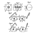
- the universal ametropia corrector which is represented in FIG. 1, comprises an opaque zone 2 surrounding a central zone 3 transparent, of small dimension and forming "diaphranme".
- This transparent central zone 3 can have any suitable shape, in particular circular, polygonal, elliptical or other, as well as the opaque zone? the entran has sucface the area opaque 2 is homothetic to that of the surface of the central transparent zone 3 or different from this homothetic surface.
- the surface of the transparent central zone 3 forming a diaphragm must be between 0.2 and 3.5 mm 2.
- a surface of 0.5 mm2 makes it possible to obtain a good correction for common ametropias ranging from 0.25 to 10 diopters, the opaque zone 2 which surrounds it having a minimum surface of 27 mm 2 . If we respect these conditions, we get a clear vision, whatever the visual state to compensate and without aberrations.
- the corrector according to the invention makes it possible, due to the presence of the continuous opaque zone of small dimensions, to obtain clear images while preserving the peripheral visual field.
- the opaque zone 2 can be completely independent and it can constitute a sort of "washer” made of an opaque material, the transparent central zone 3 being formed by a single hole.
- the opaque zone 2 can also be deposited or glued to a support 4 made of transparent material as shown in FIG. 1, the transparent central zone 3 then being constituted by the support portion 4 being located in the center of the opaque zone 2.
- the transparent support 4 can have the form of a usual spectacle lens, as shown in FIGS. 2 and 3.
- FIG. 2 illustrates a pair of glasses comprising a common transverse and horizontal bar 5 under which are fixed the two transparent supports 4 associated respectively with the two eyes.
- Each of these supports can be moved on the bar 5, for example by 2 mm. to allow adaptation of the distance between the two supports 4 to the interpupillary distance of the spectacle wearer. Once the appropriate distance is obtained, we set definitely each support 4 on the bar 5, by any appropriate means, for example by a clip or a quick bonding.
- the frame of the pair of glasses is made up of two parts each comprising a transparent support 4 on which is hinged, around a hinge 6, a branch 7 of the frame.
- the two supports 4 are also connected horizontally by an intermediate bar 8 of variable length suitable for the interpupillary distance of the wearer.
- This intermediate bar 8 can be made in telescopic form.
- the corrector according to the invention can also form part of an eyeglass resting on the nose, the two “washers” then being connected, by a single wire, to the part of the eyeglass bearing on the nose.
- FIG. 4 illustrates the use of the corrector according to the invention as a contact lens.
- This contact lens comprises, as in the previous cases, a transparent support 9 having the shape of a curved surface whose radius of curvature corresponds to the cornea treated.
- This transparent support 9 also has an opaque zone 11 surrounding a transparent central zone 12 of small size.
- FIG. 5 illustrates the case of several opaque zones 2 provided on the same transparent support 4 and aligned along a horizontal plane H and each surrounding a transparent central zone 3 of small dimension. Three neighboring opaque zones 2 are sufficient to ensure good vision in the horizontal field. A similar arrangement can also be adopted in the vertical plane.
- the corrector may consist of a piece of an opaque perforated strip, at regular intervals, of holes arranged in staggered rows, the distance between the elementary holes forming diaphragms being greater than or equal to 3 mm.
- this corrector in the case of use of the corrector in the form of a pair of glasses, this corrector can be constituted by an opaque washer, transparent in its central part, which is deposited, by screen printing or by any other means, on each of the two lenses of a pair of conventional spectacles, and this in locations corresponding to the interpupillary distance from the wearer of the spectacles.
- Other auxiliary washers are arranged around this main washer corresponding to the interpupillary distance. This allows the use of a single standard frame, fitted with its transparent lenses, for all users, regardless of the interpupillary distance of these.
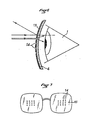
- the corrector which is shown in FIGS. 6 and 7, in front of the eye 1, comprises a transparent support 4, for example made of glass or plastic, on the front face of which a thin layer 13 reflecting light is deposited.
- This layer 13 does not reflect the entire incident light beam, but it lets a more or less weak part of this incident light flux pass, so that the eye can see through the relatively opaque thin layer 13, but with a weakening of the brightness.
- this thin reflective and slightly transparent layer 13 are left transparent point zones 14 of small dimension and forming "diaphragms". These transparent point zones 14 can also be formed by holes drilled right through in the transparent support 4 and the layer thin reflective 13.
- each transparent point zone 14 forming the strip must be between 0.2 and 3.5 mm 2 and it is preferably around 1 mm 2 .
- the transparent support 4 can have the usual shape of a glass - of a pair of glasses as shown in FIG. 7.
- each glass has a reflective front surface 13 in the central part of which a group is formed transparent point zones 14 distant from each other.
- These zones 14 are advantageously distributed at a minimum distance of approximately 3mm from each other. They can be distributed in a matrix arrangement, that is to say in rows and columns, as shown in FIG. 7.
- the corrector can constitute a contact lens, also called “contact lens or lens”, on which a central transparent zone surrounded by a border is left, by screen printing or any other means. opaque to light.
- contact lens also called "contact lens or lens”
- the manufacture of these lenses is considerably simplified compared to contact lenses currently known: in fact a single model is suitable for all people with any visual need.
- two or three different radii of curvature can be provided depending on the diameters of the corneas to be treated.
- These lenses must have low mobility in front of the pupil. If they are made of a suitable material, disposable lenses are obtained, maintenance-free or permanent wear.
- the corrector constitutes a contact lens or contact lens
- the known opaque zone preferably a reservoir of a liquid product which can be used for therapeutic or hygienic purposes.
Abstract
Un correcteur universel de vision s'appliquant notamment à la myopie, l'hypermétropie, l'astigmatisme et la presbytie comprend, en avant de l'oeil, une zone opaque (2) entourant une petite zone centrale (3) située dans l'axe de vision, cette petite zone centrale (3) transparente formant diaphragme et créant une image rétinienne réduite donnant une vision nette. La zone opaque (2) est continue, elle a un diamètre moyen minimal de 3 mm et maximal de 8 mm pour conserver la vision périphérique et la zone centrale transparente (3) a une surface allant de 0,2 à 3,5 mm² et de préférence de 0,5 à 1 mm².A universal vision corrector applying in particular to myopia, hyperopia, astigmatism and presbyopia comprises, in front of the eye, an opaque zone (2) surrounding a small central zone (3) located in the axis of vision, this small transparent central area (3) forming a diaphragm and creating a reduced retinal image giving clear vision. The opaque zone (2) is continuous, it has a minimum average diameter of 3 mm and maximum of 8 mm to maintain peripheral vision and the transparent central zone (3) has a surface ranging from 0.2 to 3.5 mm² and preferably from 0.5 to 1 mm².
Description
La présente invention concerne un correcteur universel de vision s'appliquant notamment à la myopie, l'hypermétropie, l'astigmatisme et la presbytie.The present invention relates to a universal vision corrector applying in particular to myopia, hyperopia, astigmatism and presbyopia.
Jusqu'à présent, pour corriger ces divers besoins, on utilise des verres correcteurs don.t les foyers sont tels que dans tous les cas, les rayons semblent provenir du "Punctum Remotum" de l'oeil traité, ce qui a pour conséquence que l'oeil n'accommode pas.Up to now, to correct these various needs, corrective glasses have been used. The focal points are such that in all cases, the rays seem to come from the "Punctum Remotum" of the treated eye, which has the consequence that the eye does not accommodate.
Par ailleurs on connaît également des lunettes dont les "verres" sont en fait constitués de plaques opaques percées de trous. Une telle paire de lunettes est décrite par exemple dans le brevet US-A-3 967 885. Une paire de lunettes de ce type présente l'inconvénient que l'opacité globale de la surface des verres entraîne une occlusion latérale de la vision et une dilatation permanente de la pupille qui provoque à son tour une tétanisation du muscle qui commande la dilatation et la contraction de la pupille.Furthermore, glasses are also known, the "glasses" of which in fact consist of opaque plates pierced with holes. Such a pair of glasses is described for example in US Pat. No. 3,967,885. A pair of glasses of this type has the drawback that the overall opacity of the surface of the glasses results in lateral occlusion of vision and a permanent dilation of the pupil which in turn causes tetanization of the muscle which controls the dilation and contraction of the pupil.
On connaît également, ainsi qu'il est décrit dans le brevet US 3 794 414, une lentille de contact bifocale conçue pour la vision de loin. Cette lentille comprend une zone centrale transparente entourée d'une succession de zones opaques individuelles séparées les unes des autres par des fentes transparentes. Or il s'est avéré à l'usage qu'une lentille de contact conforme à cebrevet ne peut en aucune manière jouer le rôle d'un correcteur universel de vision.Also known, as described in US Pat. No. 3,794,414, is a bifocal contact lens designed for far vision. This lens comprises a transparent central zone surrounded by a succession of individual opaque zones separated from each other by transparent slots. However, it has been found in use that a contact lens conforming to this patent cannot in any way play the role of a universal vision corrector.
La présente invention concerne un correcteur de vision de conception particulièrement simple.The present invention relates to a vision corrector with a particularly simple design.
A cet effet ce correcteur universel de vision comprenant, en avant de l'oeil, une zone opaque entourant une petite zone centrale située dans l'axe de vision, cette petite zone centrale transparente formant diaphragme et créant une image de rétinenne réduite donnant une visior nette, est caractérisé en ce que la zone opaque est continue, elle a un diamètre moyen minimal de 3 mm et maximal d. 8 mm pour conserver 1a vision périphérique, et la zone cen trale transparente a une surface allant de 0,2 à 3,5 mm2 et de préférence de 0,5 % à 1 mm2,To this end, this universal vision corrector comprising, in front of the eye, an opaque zone surrounding a small central zone situated in the axis of vision, this small transparent central zone forming a diaphragm and creating a reduced retinal image giving a visior clear, is characterized in that the opaque zone is continuous, it has a minimum average diameter of 3 mm and maximum d. 8 mm to maintain the peripheral vision, and the central transparent zone has a surface ranging from 0.2 to 3.5
Par "zone opaque" on entend toute surface empêchant la perception par l'oeil des rayons lumineux tandis que la "zone transparente", constituée d'un trou ou d'une portion solide, laisse, au contraire, passer les rayons lumineux.By "opaque zone" is meant any surface preventing light rays from being perceived by the eye, while the "transparent zone", consisting of a hole or a solid portion, lets the light rays pass, on the contrary.
La zone opaque entourant la zone centrale transparente peut être réalisée d'une manière indépendante, en une matière opaque, en formant une sorte de "rondelle" ou bien encore elle peut être formée sur la face avant ou arrière d'un support en matière transparente. La zone centrale transparente peut être constituée, dans ce cas, par la matière du support ou bien par un trou percé dans celui-ci.The opaque zone surrounding the central transparent zone can be produced independently, in an opaque material, by forming a sort of "washer" or else it can be formed on the front or rear face of a support in transparent material. . The transparent central zone can be formed, in this case, by the material of the support or by a hole drilled in it.
Un seul et même correcteur de vision suivant l'invention peut être utilisé pour corriger les états visuels classiques à savoir myopie, hypermétropie, astigmatisme et presbytie du fait que l'image rétinienne réduite donne une vision nette tout en conservant le champ périphérique, ce qui est indispensable dans la vie sociale et au plan pratique.A single vision corrector according to the invention can be used to correct the classic visual states, namely myopia, hyperopia, astigmatism and presbyopia because the reduced retinal image gives a clear vision while retaining the peripheral field, which is essential in social life and in practical terms.
La zone centrale transparente a, de préférence, une surface de 0,5 à 1 mm2 et la zone opaque a également, de préférence, un diamètre de 4 à 5 mm.The transparent central zone preferably has a surface of 0.5 to 1 mm 2 and the opaque zone also preferably has a diameter of 4 to 5 mm.
Pour les amétropies courantes, allant de 0,25 4 10 dioptries, on obtient, avec le dispositif suivant l'invention, une vision correcte et ce sans aberrations pour une zone transparente centrale ayant une surface d'environ 0,8 mm2 (diamètre 1 mm).For common ametropia, ranging from 0.25 4 10 diopters, with the device according to the invention, correct vision is obtained without aberrations for a central transparent area having a surface of approximately 0.8 mm 2 (diameter 1 mm).
Du fait que l'oeil est mobile, les champs de vision verticale et horizontale sont respectivement de 1200 et 15no ; bien que le champ de vision nette ne soit que de 1 minute d'angle, on peut augmenter le champ de vision nette en associant, sur un même support transparent, plusieurs "rondelles", c'est-à-dire plusieurs zones centrales transparentes entourées respectivement de zones opaques. La distance entre les zones transparentes est fonction des diamètres de celles-ci pour éviter les interférences. Cette disposition permet de retrouver le champ normal de vision sans nécessiter une rotation de la tate.Because the eye is mobile, the vertical and horizontal fields of vision are respectively 1200 and 15n o ; although the field of vision is only 1 minute angle, you can increase the field of vision by combining, on the same transparent support, several "washers", that is to say several transparent central zones respectively surrounded by opaque areas. The distance between the transparent zones depends on the diameters of these to avoid interference. This arrangement allows to find the normal field of vision without requiring a rotation of the tate.
Les zones centrales transparentes peuv-ent avoir toute forme géométrique appropriée,par exemple circulaire, rectangulaire ou encore elliptique, la zone opaque l'entourant ayant une surface homothétique ou non.The transparent central zones can have any suitable geometric shape, for example circular, rectangular or even elliptical, the opaque zone surrounding it having a homothetic surface or not.
Le correcteur suivant l'invention peut être utilisé pour des applications très différentes. Il peut être notam_ ment utilisé sous la forme d'une paire de lunettes. Dans ce cas, il convient de respecter la distance interpupillaire qui est, pour les hommes, de 63 à 68 mm et, pour les femmes, de 60 mm à 64 mm. On peut, dans ce cas, prévoir plusieurs solutions. Suivant une première solution chaque support transparent est monté réglable en position sur une barrette transversale et horizontale commune et une fois le réglage correspondant à la distance interpupillaire obtenu, il est immobilisé en position, par tout moyen approprié. Suivant une deuxième solution la monture est réalisée en deux parties fixes, reliées entre elles par une barrette intermédiaire, de longueur convenable pour s'adapter aux distances interpupillaires des diverses personnes. Suivant une troisième solution la monture et les verres sont fixes et l'emplacement des zones ponctuelles transparentes sur chacun des deux verres est choisi en fonction de la distance interpupillaire du porteur des lunettes.The corrector according to the invention can be used for very different applications. It can in particular be used in the form of a pair of glasses. In this case, the interpupillary distance must be respected, which is, for men, from 63 to 68 mm and, for women, from 60 mm to 64 mm. We can, in this case, provide several solutions. According to a first solution, each transparent support is mounted adjustable in position on a common transverse and horizontal bar and once the adjustment corresponding to the interpupillary distance obtained, it is immobilized in position, by any appropriate means. According to a second solution, the frame is produced in two fixed parts, connected to each other by an intermediate bar, of suitable length to adapt to the interpupillary distances of the various people. According to a third solution, the frame and the lenses are fixed and the location of the transparent point areas on each of the two lenses is chosen as a function of the interpupillary distance from the wearer of the glasses.
Le correcteur suivant l'invention peut être utilisé également avec des appareils de visée tels qu'appareils photographiques, caméras, jumelles, microscopes etc, pour permettre une meilleure vision aux personnes présentant un besoin. Dans ce cas, le support transparent, présentant la zone centrale transparente bordée de la zone opaque, peut être fixé directement sur l'oculaire, par exemple par collage, ou de préférence à 1 cm de celui-ci, pour augmenter le champ de vision. On peut également former directement la zone opaque sur l'oculaire lui-même, par gravure ou tout autre moyen.The corrector according to the invention can also be used with sighting devices such as cameras, cameras, binoculars, microscopes etc., to allow better vision for people with a need. In this case, the transparent support, having the transparent central zone bordered by the opaque zone, can be fixed directly on the eyepiece, for example by gluing, or preferably at 1 cm from it, to increase the field of vision. . One can also directly form the opaque area on the eyepiece itself, by etching or any other means.
De la même façon les mêmes techniques peuvent êtr utilisées pour des lunettes de protection de soudeurs, mineurs, qlaciologues, etc..In the same way the same techniques can be used for protective glasses for welders, miners, qlaciologists, etc.
Il peut également être adapté à des lunettes pour la télévision, le support transparent étant alors légèrement coloré, ou encore à des lunettes pour la vision en relief (support transparent rouge d'un côté et bleu de l'autre).It can also be adapted to glasses for television, the transparent support then being slightly colored, or even to glasses for vision in relief (transparent support red on one side and blue on the other).
En ce qui concerne les applications précédentes, un oeil normal n'est en fait pas perturbé par les correcteurs suivant l'invention que constituent les zones opaques entourant les zones centrales transparentes. Il y a une simple augmentation du contraste et une compatibilité totale. nn sait par expérience optométrique, que le confort optimal de vision d'un oeil normal est obtenu lorsque devant cet oeil est placé un diaphragme appelé " trou sténopéique".With regard to the preceding applications, a normal eye is in fact not disturbed by the correctors according to the invention which constitute the opaque zones surrounding the transparent central zones. There is a simple increase in contrast and full compatibility. We know from optometric experience that the optimal viewing comfort of a normal eye is obtained when a diaphragm called "pinhole hole" is placed in front of this eye.
On décrira ci-après,à titre d'exemples non limitatifs, diverses formes d'exécution de la présente invention, en référence au dessin annexé sur lequel :
- La figure 1 est une vue en élévation d'un correcteur d'amétropies .
- La figure 2 est une vue en perspective d'une application du.correcteur sous la forme d'une paire de lunettes.
- La figure 3 est une vue en perspective d'une variante d'exécution d'une paire de lunettes utilisant le correcteur suivant l'invention.
- La figure 4 est une vue en coupe verticale schématique d'un correcteur utilisé en tant que lentille de contact.
- La figure 5 est une vue en élévation d'une variante d'exécution du correcteur.
- La figure 6 est une vue en coupe verticale schématique d'une autre variante d'exécution du correcteur .
- La figure 7 est une vue en élévation d'un correcteur réalisé sous la forme d'une paire de lunettes.
- Figure 1 is an elevational view of an ametropia corrector.
- Figure 2 is a perspective view of an application of the corrector in the form of a pair of glasses.
- Figure 3 is a perspective view of an alternative embodiment of a pair of glasses using the corrector according to the invention.
- Figure 4 is a schematic vertical sectional view of a corrector used as a contact lens.
- Figure 5 is an elevational view of an alternative embodiment of the corrector.
- Figure 6 is a schematic vertical sectional view of another alternative embodiment of the corrector.
- Figure 7 is an elevational view of a corrector made in the form of a pair of glasses.
Le correcteur universel d'amétropies suivant l'invention qui est représenté sur la figure 1, comprend une zone opaque 2 entourant une zone centrale 3 transparente, de petite dimension et formant "diaphranme". Cette zone centrale transparente 3 peut avoir toute forme appropriée, notamment circulaire, polygonale, elliptique ou autre, de même que la zone opaque ? l'enteuran a sucface le la zone opaque 2 est homothétique de celle de la surface de la zone transparente centrale 3 ou différente de cette surface homothétique.The universal ametropia corrector according to the invention which is represented in FIG. 1, comprises an
A la suite de nombreux essais il s'est révélé que la surface de la zone centrale transparente 3 formant diaphragme doit être comprise entre 0,2 et 3,5 mm2. Par exemple une surface de 0,5 mm2 permet d'obtenir une bonne correction pour les amétropies courantes allant de 0,25 à 10 dioptries, la zone opaque 2 qui l'entoure ayant une surface minimale de 27 mm2. Si on respecte ces conditions, on obtient une vision nette, quel que soit l'état visuel à compenser et ce sans aberrations.Following numerous tests, it has been found that the surface of the transparent
On a constaté d'une manière surprenante que le correcteur suivant l'invention permettait, du fait de la présence de la zone opaque continue de faibles dimensions, d'obtenir des images nettes tout en conservant le champ visuel périphérique.It has been found, surprisingly, that the corrector according to the invention makes it possible, due to the presence of the continuous opaque zone of small dimensions, to obtain clear images while preserving the peripheral visual field.
La zone opaque 2 peut être totalement indépendante et elle peut constituer une sorte de "rondelle" en une matière opaque, la zone centrale transparente 3 étant formée par un simple trou. La zone opaque 2 peut être aussi déposée ou collée sur un support 4 en matière transparente comme il est représenté sur la figure 1, la zone centrale transparente 3 étant alors constituée par la portion de support 4 se trouvant au centre de la zone opaque 2.The
Le support transparent 4 peut avoir la forme d'un verre de lunettes habituel, comme il est représenté sur les figures 2 et 3.The
La figure 2 illustre une paire de lunettes comportant une barrette transversale et horizontale commune 5 sous laquelle sont fixés les deux supports transparents 4 associés respectivement aux deux yeux. Chacun de ces support: peut être déplacé sur la barrette 5, par exemple de 2 mm. pour permettre une adaptation de la distance entre les deu' supports 4 à la distance interpupillaire du porteur de lunettes. Une fois la distance appropriée obtenue, on fixe définitivement chaque support 4 sur la barrette 5, par tous moyens appropriés, par exemple par un clips ou un collage rapide.FIG. 2 illustrates a pair of glasses comprising a common transverse and horizontal bar 5 under which are fixed the two
Dans la variante d'exécution illustrée sur la figure 3, la monture de la paire de lunettes est constituée en deux parties comprenant chacune un support transparent 4 sur lequel est articulé, autour d'une charnière 6, une branche 7 de la monture. Les deux supports 4 sont en outre reliés horizontalement par une barrette intermédiaire 8 de longueur variable convenable pour la distance interpupillaire du porteur. Cette barrette intermédiaire 8 peut être réalisée sous forme télescopique.In the alternative embodiment illustrated in FIG. 3, the frame of the pair of glasses is made up of two parts each comprising a
Le correcteur suivant l'invention peut faire également partie d'un lorgnon reposant sur le nez, les deux "rondelles" étant alors reliées, par un simple fil, à la partie du lorgnon prenant appui sur le nez.The corrector according to the invention can also form part of an eyeglass resting on the nose, the two "washers" then being connected, by a single wire, to the part of the eyeglass bearing on the nose.
La figure 4 illustre l'utilisation du correcteur suivant l'invention en tant que lentille de contact. Cette lentille de contact comporte, comme dans les cas précédents, un support transparent 9 présentant la forme d'une surface courbe dont le rayon de courbure correspond à la cornée traitée. Ce support transparent 9 présente également une zone opaque 11 entourant une zone centrale transparente 12 de petite dimension.FIG. 4 illustrates the use of the corrector according to the invention as a contact lens. This contact lens comprises, as in the previous cases, a transparent support 9 having the shape of a curved surface whose radius of curvature corresponds to the cornea treated. This transparent support 9 also has an opaque zone 11 surrounding a transparent central zone 12 of small size.
La figure 5 illustre le cas de plusieurs zones opaques 2 prévues sur un même support transparent 4 et alignées suivant un plan horizontal H et entourant chacune une zone centrale transparente 3 de petite dimension. Trois-zones opaques 2 voisines suffisent pour assurer une bonne vision dans le champ horizontal. Une disposition similaire peut être également adoptée dans le plan vertical.FIG. 5 illustrates the case of several
Suivant une autre variante d'exécution le correcteur peut être constitué par un morceau d'une bande opaque perforée, à des intervalles réguliers, de trous disposés en quinconce, la distance entre les trous élémentaires formant diaphragmes étant supérieure ou éqale à 3 mm.According to another alternative embodiment, the corrector may consist of a piece of an opaque perforated strip, at regular intervals, of holes arranged in staggered rows, the distance between the elementary holes forming diaphragms being greater than or equal to 3 mm.
Il est ainsi possible de couper à la longueur désirée des morceaux de bande opaque perforée des trous formant diaphragmes, ces morceaux de bande pouvant être collés tels quels sur des supports transparents.It is thus possible to cut to the desired length pieces of opaque strip perforated with holes forming diaphragms, these pieces of strip being able to be glued as such on transparent supports.
Suivant une autre variante de l'invention, dans le cas d'une utilisation du correcteur sous la forme d'une paire de lunettes, ce correcteur peut être constitué par une rondelle opaque, transparente dans sa partie centrale, laquelle est déposée, par sérigraphie ou par tout autre moyen, sur chacun des deux verres d'une paire de lunettes classiques, et ce en des emplacements correspondant à la dis tance interpupillaire du porteur des lunettes. Autour de cette rondelle principale correspondant à la distance interpupillaire sont disposées en quinconce d'autres rondelles auxiliaires.Ceci permet d'utiliser une seule et même monture standard, équipée de ses verres transparents, pour tous les utilisateurs, quelle que soit la distance interpupillaire de ceux-ci.According to another variant of the invention, in the case of use of the corrector in the form of a pair of glasses, this corrector can be constituted by an opaque washer, transparent in its central part, which is deposited, by screen printing or by any other means, on each of the two lenses of a pair of conventional spectacles, and this in locations corresponding to the interpupillary distance from the wearer of the spectacles. Other auxiliary washers are arranged around this main washer corresponding to the interpupillary distance. This allows the use of a single standard frame, fitted with its transparent lenses, for all users, regardless of the interpupillary distance of these.
Le correcteur qui est représenté sur les figures 6 et 7, en avant de l' oeil 1, comprend un support transparent 4, par exemple en verre ou matière plastique, sur la face antérieure duquel est déposée une couche mince 13 réfléchissant la lumière. Cette couche 13 ne réfléchit pas la totalité du faisceau lumineux incidentmais elle laisse passer une partie plus ou moins faible de ce flux lumineux incident, si bien que l'oeil peut voir à travers la couche mince 13 relativement opaque, mais avec un affaiblissement de la luminosité. Dans cette couche mince 13 réfléchissante et faiblement transparente sont laissées des zones ponctuelles transparentes 14 de petite dimension et formant "diaphragmes".Ces zones ponctuelles transparentes 14 peuvent aussi être constituées par des trous percés de part en part dans le support transparent 4 et la couche mince réfléchissante 13.The corrector which is shown in FIGS. 6 and 7, in front of the eye 1, comprises a
A la suite de nombreux essais il s'est révélé que la surface de chaque zone ponctuelle transparente 14 formant liaphraque doit être comprise entre 0,2 et 3,5 mm2 et elle eat de préféeopoe voisine de 1 mm2.Following numerous tests, it has been found that the surface of each
Le support transparent 4 peut avoir la forme habituelle d'un verre-d'une paire de lunettes comme il est représenté sur la figure 7. Dans ce cas chaque verre présente une surface antérieure réfléchissante 13 dans la partie centrale de laquelle est formé un groupe de zones ponctuelles transparentes 14 distantes les unes des autres. Ces zones 14 sont avantageusement réparties à une distance minimale d'environ 3mm les unes des autres. Elles peuvent être réparties suivant une disposition matricielle, c'est-à-dire en rangées et colonnes, comme il est représenté sur la figure 7.The
Dans le cas de la correction permanente de la vision, le correcteur peut constituer une lentille cornéenne, appelée encore "lentille ou verre de contact", sur laquelle on laisse, par sérigraphie ou tout autre moyen, une zone transparente centrale entourée d'une bordure opaque à la lumière. La fabrication de ces lentilles est considérablement simplifiée par rapport aux lentilles de contact connues actuellement: en effet un seul modèle convient pour toutes les personnes présentant un besoin visuel quel qu'il soit. On peut éventuellement prévoir deux ou trois rayons de courbure différents en fonction des diamètres des cornées à traiter.In the case of permanent vision correction, the corrector can constitute a contact lens, also called "contact lens or lens", on which a central transparent zone surrounded by a border is left, by screen printing or any other means. opaque to light. The manufacture of these lenses is considerably simplified compared to contact lenses currently known: in fact a single model is suitable for all people with any visual need. Optionally, two or three different radii of curvature can be provided depending on the diameters of the corneas to be treated.
Ces lentilles doivent avoir une mobilité faible devant la pupille. Si elles sont fabriquées dans une matière adéquate, on obtient des lentilles jetables, sans entretien et ou à port permanent.These lenses must have low mobility in front of the pupil. If they are made of a suitable material, disposable lenses are obtained, maintenance-free or permanent wear.
Dans le cas où le correcteur constitue une lentille cornéenne ou lentille de contact,on peut utiliser preféren- tiellement la zone opaque connue un réservoir d'un produit liquide utilisable h des fins thérapeutiques ou hygiéniques.In the case where the corrector constitutes a contact lens or contact lens, it is preferable to use the known opaque zone preferably a reservoir of a liquid product which can be used for therapeutic or hygienic purposes.
Claims (11)
Applications Claiming Priority (6)
| Application Number | Priority Date | Filing Date | Title |
|---|---|---|---|
| FR8317244 | 1983-10-28 | ||
| FR8317244A FR2554249B1 (en) | 1983-10-28 | 1983-10-28 | UNIVERSAL CORRECTOR OF AMETROPIES OF THE EYE |
| FR8400388 | 1984-01-12 | ||
| FR8400388A FR2558269B2 (en) | 1984-01-12 | 1984-01-12 | UNIVERSAL CORRECTOR OF AMETROPIES OF THE EYE |
| FR8411447A FR2568022B1 (en) | 1984-07-19 | 1984-07-19 | UNIVERSAL CORRECTOR OF AMETROPIES OF THE EYE |
| FR8411447 | 1984-07-19 |
Publications (2)
| Publication Number | Publication Date |
|---|---|
| EP0141736A2 true EP0141736A2 (en) | 1985-05-15 |
| EP0141736A3 EP0141736A3 (en) | 1985-06-19 |
Family
ID=27251180
Family Applications (1)
| Application Number | Title | Priority Date | Filing Date |
|---|---|---|---|
| EP84402162A Ceased EP0141736A3 (en) | 1983-10-28 | 1984-10-26 | Universal vision correcting apparatus |
Country Status (6)
| Country | Link |
|---|---|
| US (1) | US4958922A (en) |
| EP (1) | EP0141736A3 (en) |
| AU (1) | AU3506884A (en) |
| CA (1) | CA1264579A (en) |
| MA (1) | MA20257A1 (en) |
| WO (1) | WO1985002028A1 (en) |
Cited By (6)
| Publication number | Priority date | Publication date | Assignee | Title |
|---|---|---|---|---|
| EP0189331A1 (en) * | 1985-01-24 | 1986-07-30 | Kabushiki Kaisha Shuho | Objective material |
| FR2618915A1 (en) * | 1987-05-25 | 1989-02-03 | Maignant Albert | Correcting lens for relieving disorders due to occular myopathy |
| FR2646524A1 (en) * | 1989-04-28 | 1990-11-02 | Blanie Paul | Improved spectacles |
| FR2655431A1 (en) * | 1989-12-04 | 1991-06-07 | Bernard Rene | STENOPEIC GLASSES. |
| WO1996013750A1 (en) * | 1994-11-01 | 1996-05-09 | Laser Micro Präzision Lmp Gmbh | Sight-improving perforated blind and seeing aid with sight-improving perforated blind |
| WO2000005618A1 (en) * | 1998-07-23 | 2000-02-03 | Peter Joseph Duthie | Ophthalmic device |
Families Citing this family (18)
| Publication number | Priority date | Publication date | Assignee | Title |
|---|---|---|---|---|
| GB8529595D0 (en) * | 1985-12-02 | 1986-01-08 | Iris Optics Ltd | Reading glasses |
| AU601026B2 (en) * | 1987-03-10 | 1990-08-30 | James Shreenan | Golfer position viewing device |
| WO2000052516A2 (en) | 1999-03-01 | 2000-09-08 | Boston Innovative Optics, Inc. | System and method for increasing the depth of focus of the human eye |
| AU2001257619A1 (en) * | 2000-04-25 | 2001-11-12 | Voyant.Com | Device for alleviating computer vision syndrome |
| US7628810B2 (en) | 2003-05-28 | 2009-12-08 | Acufocus, Inc. | Mask configured to maintain nutrient transport without producing visible diffraction patterns |
| US20050046794A1 (en) | 2003-06-17 | 2005-03-03 | Silvestrini Thomas A. | Method and apparatus for aligning a mask with the visual axis of an eye |
| US7976577B2 (en) | 2005-04-14 | 2011-07-12 | Acufocus, Inc. | Corneal optic formed of degradation resistant polymer |
| US7857448B2 (en) * | 2006-05-04 | 2010-12-28 | Proview Optical Group Corp. | Astigmia correcting eyeglasses |
| US20070258041A1 (en) * | 2006-05-04 | 2007-11-08 | Augustus Huang | Astigmia correcting eyeglasses |
| EP2464311B1 (en) | 2009-08-13 | 2017-11-15 | AcuFocus, Inc. | Masked intraocular implants and lenses |
| USD656526S1 (en) | 2009-11-10 | 2012-03-27 | Acufocus, Inc. | Ocular mask |
| US9224024B2 (en) * | 2011-11-11 | 2015-12-29 | Honeywell International, Inc. | Invariant design image capture device |
| JP6046160B2 (en) | 2011-12-02 | 2016-12-14 | アキュフォーカス・インコーポレーテッド | Ophthalmic mask with selective spectral transmission |
| US9204962B2 (en) | 2013-03-13 | 2015-12-08 | Acufocus, Inc. | In situ adjustable optical mask |
| US9427922B2 (en) | 2013-03-14 | 2016-08-30 | Acufocus, Inc. | Process for manufacturing an intraocular lens with an embedded mask |
| TWI485465B (en) * | 2013-05-16 | 2015-05-21 | Tzoo Ying Entpr Co Ltd | An eye protection device |
| CN105182563A (en) * | 2015-08-27 | 2015-12-23 | 杨克忠 | Cranny covering eyeglass for eliminating eye astigmatism and method for eliminating astigmatism |
| CN115244452A (en) * | 2020-03-01 | 2022-10-25 | 恩塔米克控股有限公司 | Myopia management eyeglass lens that can convert a monocular eyeglass lens into an optical film having non-refractive opaque characteristics |
Citations (6)
| Publication number | Priority date | Publication date | Assignee | Title |
|---|---|---|---|---|
| FR7201E (en) * | 1906-11-23 | 1907-06-01 | Societe A. A. Tunmer & C° | Improvements to motorists' glasses |
| FR398850A (en) * | 1908-04-03 | 1909-06-15 | Max Landesberg | Binocle or glasses without glasses that can be used for myopic and presbyopic |
| DE621084C (en) * | 1935-11-01 | Max Jeanneret Dr | Shooting glasses | |
| FR1020646A (en) * | 1950-06-21 | 1953-02-09 | Methods and devices for eliminating glare from automobile headlights and all other sources of light | |
| CH447650A (en) * | 1966-05-04 | 1967-11-30 | Courvoisier Jean Pierre | Device intended to render the learned raster lines imperceptible to the eye, as well as the vibration of a moving image observed on a screen |
| FR2389912A1 (en) * | 1977-05-06 | 1978-12-01 | Carreau Bernard | Protective spectacle lens construction - reduces light transmitted to peripheral retinal regions using fibre optic patch with hole in centre |
Family Cites Families (7)
| Publication number | Priority date | Publication date | Assignee | Title |
|---|---|---|---|---|
| US459563A (en) * | 1891-09-15 | Device for assisting vision | ||
| FR389850A (en) * | 1908-05-02 | 1908-09-19 | Richard Zelle | Matchbox with calendar and cigar cutter |
| US2856813A (en) * | 1955-05-03 | 1958-10-21 | Kudelko Antonia | Spectacle frame with adjustable bridge and temples |
| FR1330277A (en) * | 1962-05-09 | 1963-06-21 | Protective and corrective glasses with adjustable diaphragm for television and cinema viewers | |
| US3507566A (en) * | 1968-04-29 | 1970-04-21 | Arthur A Knapp | Contact lens and spectacle lens structure |
| US4249803A (en) * | 1979-07-10 | 1981-02-10 | William H. Byler | Optical device for pre-operative cataract patients |
| FR2498769B2 (en) * | 1979-07-12 | 1988-09-23 | Bernet Roger | IMPROVED STENOPEIC GLASSES |
-
1984
- 1984-10-26 EP EP84402162A patent/EP0141736A3/en not_active Ceased
- 1984-10-26 WO PCT/FR1984/000244 patent/WO1985002028A1/en unknown
- 1984-10-26 MA MA20481A patent/MA20257A1/en unknown
- 1984-10-26 AU AU35068/84A patent/AU3506884A/en not_active Abandoned
- 1984-10-29 CA CA000466530A patent/CA1264579A/en not_active Expired - Lifetime
-
1989
- 1989-03-06 US US07/319,904 patent/US4958922A/en not_active Expired - Fee Related
Patent Citations (6)
| Publication number | Priority date | Publication date | Assignee | Title |
|---|---|---|---|---|
| DE621084C (en) * | 1935-11-01 | Max Jeanneret Dr | Shooting glasses | |
| FR7201E (en) * | 1906-11-23 | 1907-06-01 | Societe A. A. Tunmer & C° | Improvements to motorists' glasses |
| FR398850A (en) * | 1908-04-03 | 1909-06-15 | Max Landesberg | Binocle or glasses without glasses that can be used for myopic and presbyopic |
| FR1020646A (en) * | 1950-06-21 | 1953-02-09 | Methods and devices for eliminating glare from automobile headlights and all other sources of light | |
| CH447650A (en) * | 1966-05-04 | 1967-11-30 | Courvoisier Jean Pierre | Device intended to render the learned raster lines imperceptible to the eye, as well as the vibration of a moving image observed on a screen |
| FR2389912A1 (en) * | 1977-05-06 | 1978-12-01 | Carreau Bernard | Protective spectacle lens construction - reduces light transmitted to peripheral retinal regions using fibre optic patch with hole in centre |
Cited By (10)
| Publication number | Priority date | Publication date | Assignee | Title |
|---|---|---|---|---|
| EP0189331A1 (en) * | 1985-01-24 | 1986-07-30 | Kabushiki Kaisha Shuho | Objective material |
| US4750812A (en) * | 1985-01-24 | 1988-06-14 | Kabushika Kaisha Shuho | Objective observation optical material |
| FR2618915A1 (en) * | 1987-05-25 | 1989-02-03 | Maignant Albert | Correcting lens for relieving disorders due to occular myopathy |
| FR2646524A1 (en) * | 1989-04-28 | 1990-11-02 | Blanie Paul | Improved spectacles |
| EP0480113A1 (en) * | 1989-04-28 | 1992-04-15 | Paul Blanié | Improved spectacles |
| FR2655431A1 (en) * | 1989-12-04 | 1991-06-07 | Bernard Rene | STENOPEIC GLASSES. |
| WO1991008506A1 (en) * | 1989-12-04 | 1991-06-13 | Bernard Rene George | Stenopaic spectacles |
| WO1996013750A1 (en) * | 1994-11-01 | 1996-05-09 | Laser Micro Präzision Lmp Gmbh | Sight-improving perforated blind and seeing aid with sight-improving perforated blind |
| WO2000005618A1 (en) * | 1998-07-23 | 2000-02-03 | Peter Joseph Duthie | Ophthalmic device |
| GB2345350A (en) * | 1998-07-23 | 2000-07-05 | Peter Joseph Duthie | Ophthalmic device |
Also Published As
| Publication number | Publication date |
|---|---|
| EP0141736A3 (en) | 1985-06-19 |
| US4958922A (en) | 1990-09-25 |
| MA20257A1 (en) | 1985-07-01 |
| CA1264579A (en) | 1990-01-23 |
| WO1985002028A1 (en) | 1985-05-09 |
| AU3506884A (en) | 1985-05-22 |
Similar Documents
| Publication | Publication Date | Title |
|---|---|---|
| CA1264579A (en) | Universal vision corrector | |
| BE1013846A5 (en) | Variable spectacle lens for varying the focal length comprises rear ring spaced from the front ring by hinges and with an actuator while inside diameter has line of contact between free area of the membrane | |
| EP3642667B1 (en) | Orthokeratology contact lens for treating myopia | |
| CA2708516C (en) | Progressive ophthalmic lens | |
| FR2584823A1 (en) | PROGRESSIVE MULTIFOCAL LENS AND GLASSES EMPLOYING THIS LENS | |
| FR2545615A1 (en) | PROGRESSIVE MULTIFOCAL OPHTHALMIC LENS | |
| FR2533708A1 (en) | PROGRESSIVE MULTIFOCAL OPHTHALMIC LENS | |
| FR2508186A1 (en) | OPHTHALMIC LENS WITH PROGRESSIVE POWER | |
| FR2908897A1 (en) | COLORED OPHTHALMIC LENSES MULTI-SHADED. | |
| FR2888344A1 (en) | OPHTHALMIC LENS | |
| US20080273164A1 (en) | Eyewear with pinhole aperture and lens | |
| FR2924824A1 (en) | PROGRESSIVE LENS OF OPHTHALMIC EYEWEAR HAVING AN ADDITIONAL ZONE OF INTERMEDIATE VISION | |
| FR2600430A1 (en) | Spectacles having removable extra lenses | |
| WO2009141509A1 (en) | Ophthalmic glass and spectacles comprising at least such one glass | |
| FR2582416A1 (en) | Bifocal contact lens | |
| US5971541A (en) | Correction of astigmatism using rotationally symmetric contact lenses | |
| CA3076789C (en) | Assembly consisting of a pair of multifocal ocular implants | |
| FR2622984A1 (en) | Contact lens forming a solar filter | |
| EP0051613B1 (en) | Temporary optical correcting device allowing the choice of naked rims | |
| FR2948467A1 (en) | MASK OF VISION | |
| FR2554249A1 (en) | Universal corrector of ametropia of the eye | |
| FR2568022A1 (en) | Universal corrector for ametropia of the eye | |
| JPH063630A (en) | Glasses | |
| WO1991008506A1 (en) | Stenopaic spectacles | |
| EP1114351B1 (en) | Method for rapidly mounting eyepieces in a spectacle frame |
Legal Events
| Date | Code | Title | Description |
|---|---|---|---|
| PUAI | Public reference made under article 153(3) epc to a published international application that has entered the european phase |
Free format text: ORIGINAL CODE: 0009012 |
|
| PUAL | Search report despatched |
Free format text: ORIGINAL CODE: 0009013 |
|
| AK | Designated contracting states |
Designated state(s): AT BE CH DE GB IT LI LU NL SE |
|
| AK | Designated contracting states |
Designated state(s): AT BE CH DE GB IT LI LU NL SE |
|
| RTI1 | Title (correction) | ||
| 17P | Request for examination filed |
Effective date: 19851115 |
|
| 17Q | First examination report despatched |
Effective date: 19870310 |
|
| STAA | Information on the status of an ep patent application or granted ep patent |
Free format text: STATUS: THE APPLICATION HAS BEEN REFUSED |
|
| 18R | Application refused |
Effective date: 19890707 |
|
| APAF | Appeal reference modified |
Free format text: ORIGINAL CODE: EPIDOSCREFNE |