EP0141623A2 - Security door system - Google Patents
Security door system Download PDFInfo
- Publication number
- EP0141623A2 EP0141623A2 EP84307336A EP84307336A EP0141623A2 EP 0141623 A2 EP0141623 A2 EP 0141623A2 EP 84307336 A EP84307336 A EP 84307336A EP 84307336 A EP84307336 A EP 84307336A EP 0141623 A2 EP0141623 A2 EP 0141623A2
- Authority
- EP
- European Patent Office
- Prior art keywords
- door
- opening
- surround structure
- panel
- surround
- Prior art date
- Legal status (The legal status is an assumption and is not a legal conclusion. Google has not performed a legal analysis and makes no representation as to the accuracy of the status listed.)
- Granted
Links
- 230000003014 reinforcing effect Effects 0.000 claims description 2
- 238000000926 separation method Methods 0.000 claims description 2
- 238000010276 construction Methods 0.000 description 5
- 238000006073 displacement reaction Methods 0.000 description 3
- 238000009434 installation Methods 0.000 description 2
- 125000006850 spacer group Chemical group 0.000 description 2
- 230000000694 effects Effects 0.000 description 1
- 238000003780 insertion Methods 0.000 description 1
- 230000037431 insertion Effects 0.000 description 1
- 238000009418 renovation Methods 0.000 description 1
- 238000012216 screening Methods 0.000 description 1
Images


Classifications
-
- E—FIXED CONSTRUCTIONS
- E06—DOORS, WINDOWS, SHUTTERS, OR ROLLER BLINDS IN GENERAL; LADDERS
- E06B—FIXED OR MOVABLE CLOSURES FOR OPENINGS IN BUILDINGS, VEHICLES, FENCES OR LIKE ENCLOSURES IN GENERAL, e.g. DOORS, WINDOWS, BLINDS, GATES
- E06B5/00—Doors, windows, or like closures for special purposes; Border constructions therefor
- E06B5/02—Doors, windows, or like closures for special purposes; Border constructions therefor for out-buildings or cellars; Other simple closures not designed to be close-fitting
- E06B5/025—Provisional closures, e.g. temporary security doors
-
- E—FIXED CONSTRUCTIONS
- E06—DOORS, WINDOWS, SHUTTERS, OR ROLLER BLINDS IN GENERAL; LADDERS
- E06B—FIXED OR MOVABLE CLOSURES FOR OPENINGS IN BUILDINGS, VEHICLES, FENCES OR LIKE ENCLOSURES IN GENERAL, e.g. DOORS, WINDOWS, BLINDS, GATES
- E06B3/00—Window sashes, door leaves, or like elements for closing wall or like openings; Layout of fixed or moving closures, e.g. windows in wall or like openings; Features of rigidly-mounted outer frames relating to the mounting of wing frames
- E06B3/32—Arrangements of wings characterised by the manner of movement; Arrangements of movable wings in openings; Features of wings or frames relating solely to the manner of movement of the wing
- E06B3/50—Arrangements of wings characterised by the manner of movement; Arrangements of movable wings in openings; Features of wings or frames relating solely to the manner of movement of the wing with more than one kind of movement
- E06B3/52—Wings requiring lifting before opening
Definitions
- This invention relates to a door system suitable for use in protecting doorways and entrances in temporarily unoccupied premises.
- the present invention provides a security door system, which door system comprises a door surround panel structure formed and arranged to define a door opening and a door panel hingedly mounted in said door opening so as to be pivotally movable between a closed position and an open position and vertically movable through at least a limited distance and having a height relative to the door opening such as to permit vertical movement through a limited distance in its closed position, said door panel and door surround structure being provided with an interengaging security lock means for substantially securing said door at least against vertical movement and interengaging retaining means formed and arranged for retaining the door panel against pivotal movement from its closed position in a first position of the door, and for permitting pivotal movement of the door in a second position of the door vertically displaced from said first position.
- the door is hingedly mounted so that in its closed pivotal position and its first vertical position its lower edge in the plane of the door surround structure is supported immediately above, for example not more than about 6 mm, preferably not more than about 3 mm, the inner bottom edge of the door opening.
- the door surround is provided at the upper edge of said door opening on its outer face with a shield means extending downwardly therefrom by a distance greater than the separation between the upper edge of the door in the plane of the door surround structure and the inner top edge of the door opening in the closed pivotal position and first, vertical, position of the door so as to cover the gap therebetween.
- the door opening and door panel are dimensioned so that their respective edges are disposed in overlapping relation in a closed position of the door with said door on the rear face of the door surround structure, said door surround structure being provided on its rear face with securing means for securing of said door surround structure, in use of the system, to at least the jambs of said opening in said building, with the outer edges of said door surround structure disposed in overlapping relation with said lintel, jambs and threshold on the outside faces thereof in use of the door system.
- the door panel In use of the door system of the invention, the door panel is held securely in its closed position against pivotal opening movement by the retaining means and must first be lifted vertically to disengage the retaining means. This however will only be possible when the security lock means are unlocked. Since the security lock means are required to function only to prevent lifting of the door panel they can be of relatively lightweight and simple construction as the main resistance to an opening force will be borne by the retaining means. Since the respective parts of these can be fixedly secured and need not be movable in any respect they can readily be made to be of a strong construction which can contribute to the strength of the door structure itself, in a relatively simple and economic manner.
- the door system of the present invention is of relatively economic construction and can be easily secured in an opening in a building by securing the door surround structure to the existing jambs with a high degree of security and resistance to attack due inter alia to the overlapping between the door and door surround and between the door surround and jambs, lintel and threshold, while at the same time screening the securing means used to fix the door surround in place.
- the precise extent of overlap between the door surround and jambs, lintel and threshold is not critical so that by varying the extent of overlap it is possible to use a single size of door system with a range of different opening sizes.
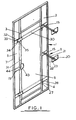
- Fig. 1 shows a door system 1 comprising door surround structure 2 defining a door opening 3 at which is hingedly mounted 4 a door panel 5.
- the door surround structure 2 is of a generally rectangular C-shaped section with the main upright 6 of the C-shape forming the front outside face 7 of the door surround structure 2.
- the door surround structure 2 is provided with a plurality of securing means 8 for securing of the structure 2 to the jambs 9, threshold 10 and lintel 11 at an opening 12 in a building 13 normally closed by an existing door 14.
- the securing means 8 comprise a clamping plate 20: a clamping bolt 21 for clamping the clamping plates 20 towards anchor plates 15 secured to the door surround 2 at the inside and outside faces of the jambs 9 etc.; and a spacer bolt 22 fixed to the clamping plate 20 with a spacer nut 23 spaced from the anchor plate at distance such that a substantially even clamping force is exerted across the anchor plate and clamping plate and the respective opposed faces of the jambs etc.
- the door panel 15 is of generally Z-shaped section at its outer edges 24 with an outwardly extending circumferential flange 25 set back from the principal plane of the door panel 5 at the rear of a shoulder 26.
- the flange 25 In the closed position of the door panel 5 the flange 25 abuts the radially inward hooked end 17 part of the door frame structure section 2 to overlap the latter on its rear face whilst the principal plane of the door panel is substantially flush with the front outside face 7 of the door surround structure 2, the door panel 5 in effect nesting radially inwardly inside the door surround structure 2 so as to be substantially supported against horizontal lateral displacement in the plane of the door system.
- the door panel is hung in the door surround structure on hinge means 4 comprising respective hinge parts 27, 28 secured to respective ones of the door surround structure and the door panel, so as to permit at least a limited degree of vertical movement of the door on said hinges.
- the structural strength and rigidity of the door panel 5 and surround 2 are reinforced at their rear with the aid of horizontal reinforcing or bracing members 30 which have at the free side 31 of the door panel 5, retaining plates 32 which project laterally behind the door surround 2. At their lower edges the retaining plates 32 have notches 33 which engage retaining pins 34 behind their heads 35 to prevent pivotal movement of the door on its hinges in an opening direction, said retaining pin and plate constituting a strong and secure retaining means for the door.
- the door panel 5 has a height in the plane of the door slightly less (e.g. about 2O mm less) than that of the opening 3 in the surround 2 so that it can be vertically displaced on its hinges in its pulled-to closed pivotal position. More specifically the structure is formed and arranged so that in a first position of the door wherein the retaining means interengage there is only a narrow clearance 36 of some 3 mm or so between the bottom edge 37 of the door 5 and the inner bottom edge 38 of the door opening 3. Between the upper edge 39 of the door 5 and the inner top edge 40 of the door opening 3 there is a larger gap 41 of up to 20 mm. This gap 41 is however concealed from view and protected against insertion of tools by a shield means in the form of a cover plate 42.
- a shield means in the form of a cover plate 42.
- a security lock means 43 which may be of any conventional form e.g. key operated, combination-type or card-operated, is provided on the door panel 5 for engagement with a suitable keeper means 44 on the door surround 2 in its locked condition.
- a suitable keeper means 44 on the door surround 2 in its locked condition.
- a suitable form of tool which can as shown be very simple is shown in Fig. 5 and comprises a thin blade 45 extending at right angles from a lever arm 46 towards one end 47 remote from a hand grip portion 48 thereof.
- the blade is inserted into the clearance and then pressure applied on the lever to tend to rotate the lever parallel to the plane of the door thereby raising one side 49 of the blade up as the other side 50 bears down on the surround 2 at the bottom of the opening 3.
- the door system in its locked condition provides strong and secure protection to an opening with the fixings used to install the system well protected against outside interference. Whilst at the same time permitting installation and removal of the system in a quick and simple manner.
- the door hinge mounting can be arranged to permit sufficient vertical displacement to lift the door panel entirely off the hinge in the open position of the door to permit easier handling of the door panel and surround separately from each other.
- Fig. 6 is a detail view of the bottom corner 51 on the hinged side of the door opening 3.
- the corner 51 is provided with a generally lazy-'Z' shaped section elongate door support member 52 having a lower web 53 connected along its outer edge 54 to the door opening bottom edge 38, and an upper web portion 55 extending rearwardly behind the door surround structure 2 above the door opening bottom edge 38.
- the height of the upper web portion 55 above the door opening bottom edge 38 is selected to be such that when the door is lifted to its second, raised, vertical position from its fully closed position and then swung open, it will swing out over and onto the door support member 52 and be supported at or above the level of its second position.
- Fig. 7 shows a modified form of retaining means 56 comprising a substantial plate-form nose 57 projecting outwardly of the free side edge 58 of the door panel 5 to which it is secured, and a keeper 59 secured to the opposed edge 60 of the door surround structure 2.
- the keeper 59 comprises a horizontal rearwardly extending plate 61 and a vertical plate 62 extending rearwardly alongside it.
- the vertical plate 62 is notched 63 at its upper corner 64 immediately adjacent the door surround structure 2 to provide a recess in which the nose 57 is received and captively held against horizontal movement corresponding to pivoting open of the door (without first raising it).
Landscapes
- Engineering & Computer Science (AREA)
- Structural Engineering (AREA)
- Civil Engineering (AREA)
- Architecture (AREA)
- Wing Frames And Configurations (AREA)
Abstract
Description
- This invention relates to a door system suitable for use in protecting doorways and entrances in temporarily unoccupied premises.
- Property which is temporarily vacant for one reason or another for example during building renovation or between tenants, is being increasingly subject to damage due to theft and extensive vandalism. Since conventional doors offer relatively little protection against a determined attack it is necessary to protect them on the outside with an additional door system which is highly resistant to attack and is simple and economic in construction and installation whilst at the same time affording access to authorised persons.
- The present invention provides a security door system, which door system comprises a door surround panel structure formed and arranged to define a door opening and a door panel hingedly mounted in said door opening so as to be pivotally movable between a closed position and an open position and vertically movable through at least a limited distance and having a height relative to the door opening such as to permit vertical movement through a limited distance in its closed position, said door panel and door surround structure being provided with an interengaging security lock means for substantially securing said door at least against vertical movement and interengaging retaining means formed and arranged for retaining the door panel against pivotal movement from its closed position in a first position of the door, and for permitting pivotal movement of the door in a second position of the door vertically displaced from said first position.
- Preferably the door is hingedly mounted so that in its closed pivotal position and its first vertical position its lower edge in the plane of the door surround structure is supported immediately above, for example not more than about 6 mm, preferably not more than about 3 mm, the inner bottom edge of the door opening.
- Desirably the door surround is provided at the upper edge of said door opening on its outer face with a shield means extending downwardly therefrom by a distance greater than the separation between the upper edge of the door in the plane of the door surround structure and the inner top edge of the door opening in the closed pivotal position and first, vertical, position of the door so as to cover the gap therebetween.
- In a preferred form of the invention for use in protecting an opening having a predetermined size and defined by a lintel, jambs and a threshold the door opening and door panel are dimensioned so that their respective edges are disposed in overlapping relation in a closed position of the door with said door on the rear face of the door surround structure, said door surround structure being provided on its rear face with securing means for securing of said door surround structure, in use of the system, to at least the jambs of said opening in said building, with the outer edges of said door surround structure disposed in overlapping relation with said lintel, jambs and threshold on the outside faces thereof in use of the door system.
- In use of the door system of the invention, the door panel is held securely in its closed position against pivotal opening movement by the retaining means and must first be lifted vertically to disengage the retaining means. This however will only be possible when the security lock means are unlocked. Since the security lock means are required to function only to prevent lifting of the door panel they can be of relatively lightweight and simple construction as the main resistance to an opening force will be borne by the retaining means. Since the respective parts of these can be fixedly secured and need not be movable in any respect they can readily be made to be of a strong construction which can contribute to the strength of the door structure itself, in a relatively simple and economic manner.
- In general the door system of the present invention is of relatively economic construction and can be easily secured in an opening in a building by securing the door surround structure to the existing jambs with a high degree of security and resistance to attack due inter alia to the overlapping between the door and door surround and between the door surround and jambs, lintel and threshold, while at the same time screening the securing means used to fix the door surround in place. In practice the precise extent of overlap between the door surround and jambs, lintel and threshold is not critical so that by varying the extent of overlap it is possible to use a single size of door system with a range of different opening sizes.
- Furthermore by using a securing means in the form of an adjustable clamping means it is possible to readily accommodate different jamb thicknesses.
- Further preferred features and advantages of the invention will appear from the following description given by way of example of a preferred embodiment illustrated with reference to the accompanying drawing in which:
- Fig. 1 is a rear perspective view of a security door system with some of the surround securing means;
- Fig. 2 is a front elevation of a door system for an apartment doorway; and
- Figs. 3 and 4 are respectively horizontal and vertical sections through the door systems of Figs. 1 and 2.
- Fig. 5 is a perspective view of a door opening tool for use with the door of Figs. 1 to 4;
- Fig. 6 is a perspective view of an optional door support suitable for use with the door of Figs. 1 to 4, and
- Fig. 7 is a perspective view of a modified form of bolt system for use in the door of Figs. 1 to 4.
- Fig. 1 shows a door system 1 comprising
door surround structure 2 defining a door opening 3 at which is hingedly mounted 4 adoor panel 5. Thedoor surround structure 2 is of a generally rectangular C-shaped section with the main upright 6 of the C-shape forming the front outsideface 7 of thedoor surround structure 2. - As may be seen in Figs. 2 to 4 the
door surround structure 2 is provided with a plurality of securing means 8 for securing of thestructure 2 to the jambs 9,threshold 10 andlintel 11 at anopening 12 in a building 13 normally closed by an existingdoor 14. - In general the securing means 8 comprise a clamping plate 20: a
clamping bolt 21 for clamping theclamping plates 20 towardsanchor plates 15 secured to thedoor surround 2 at the inside and outside faces of the jambs 9 etc.; and aspacer bolt 22 fixed to theclamping plate 20 with aspacer nut 23 spaced from the anchor plate at distance such that a substantially even clamping force is exerted across the anchor plate and clamping plate and the respective opposed faces of the jambs etc. It will be appreciated that with the abovedescribed form of securing means it is readily possible to accommodate various different thickness of jamb, threshold and lintel whilst providing a substantially secure and strong fixing of thedoor surround structure 2 around theopening 12. - The
door panel 15 is of generally Z-shaped section at itsouter edges 24 with an outwardly extendingcircumferential flange 25 set back from the principal plane of thedoor panel 5 at the rear of ashoulder 26. In the closed position of thedoor panel 5 theflange 25 abuts the radially inward hookedend 17 part of the doorframe structure section 2 to overlap the latter on its rear face whilst the principal plane of the door panel is substantially flush with the front outsideface 7 of thedoor surround structure 2, thedoor panel 5 in effect nesting radially inwardly inside thedoor surround structure 2 so as to be substantially supported against horizontal lateral displacement in the plane of the door system. - The door panel is hung in the door surround structure on hinge means 4 comprising
respective hinge parts - The structural strength and rigidity of the
door panel 5 andsurround 2 are reinforced at their rear with the aid of horizontal reinforcing or bracingmembers 30 which have at thefree side 31 of thedoor panel 5,retaining plates 32 which project laterally behind thedoor surround 2. At their lower edges theretaining plates 32 havenotches 33 which engage retainingpins 34 behind theirheads 35 to prevent pivotal movement of the door on its hinges in an opening direction, said retaining pin and plate constituting a strong and secure retaining means for the door. - As may be seen in Fig. 4 the
door panel 5 has a height in the plane of the door slightly less (e.g. about 2O mm less) than that of theopening 3 in thesurround 2 so that it can be vertically displaced on its hinges in its pulled-to closed pivotal position. More specifically the structure is formed and arranged so that in a first position of the door wherein the retaining means interengage there is only anarrow clearance 36 of some 3 mm or so between thebottom edge 37 of thedoor 5 and theinner bottom edge 38 of the door opening 3. Between theupper edge 39 of thedoor 5 and theinner top edge 40 of the door opening 3 there is alarger gap 41 of up to 20 mm. Thisgap 41 is however concealed from view and protected against insertion of tools by a shield means in the form of acover plate 42. - In order to prevent any vertical displacement of the
door panel 5 from its first position a security lock means 43 which may be of any conventional form e.g. key operated, combination-type or card-operated, is provided on thedoor panel 5 for engagement with a suitable keeper means 44 on thedoor surround 2 in its locked condition. When the security lock means 43 is unlocked thedoor panel 5 may be lifted vertically with the aid of a suitable tool through a small distance (e.g. 12 mm) sufficient to disengage the retaining means 32, 34 whereupon, and only then, the door panel can be swung open. - It will be appreciated that due to the very small clearance (which incidentally need not extend across the full width of the door but could merely be a small elongate recess in either or both of the door bottom edge and door surround) between the bottom of the
door panel 5 in the plane of the surround and the surround, only a relatively thin bladed tool can be inserted. When the security lock is in its locked condition rotation of such a thin blade would tend to result merely in its deformation. On the other hand in the unlocked condition the tool will be of sufficient strength to lift the door on its hinges, the clearance having been made to be sufficient to accommodate a blade with a strength adequate but not substantially more than that required to lift the door. - A suitable form of tool which can as shown be very simple is shown in Fig. 5 and comprises a
thin blade 45 extending at right angles from alever arm 46 towards oneend 47 remote from ahand grip portion 48 thereof. In use the blade is inserted into the clearance and then pressure applied on the lever to tend to rotate the lever parallel to the plane of the door thereby raising oneside 49 of the blade up as theother side 50 bears down on thesurround 2 at the bottom of theopening 3. - With the abovedescribed form of construction it will be appreciated that in its locked condition the door system provides strong and secure protection to an opening with the fixings used to install the system well protected against outside interference. Whilst at the same time permitting installation and removal of the system in a quick and simple manner. Naturally the door hinge mounting can be arranged to permit sufficient vertical displacement to lift the door panel entirely off the hinge in the open position of the door to permit easier handling of the door panel and surround separately from each other.
- Fig. 6 is a detail view of the
bottom corner 51 on the hinged side of the door opening 3. As may be seen in the drawing thecorner 51 is provided with a generally lazy-'Z' shaped section elongatedoor support member 52 having alower web 53 connected along itsouter edge 54 to the dooropening bottom edge 38, and anupper web portion 55 extending rearwardly behind thedoor surround structure 2 above the dooropening bottom edge 38. The height of theupper web portion 55 above the dooropening bottom edge 38 is selected to be such that when the door is lifted to its second, raised, vertical position from its fully closed position and then swung open, it will swing out over and onto thedoor support member 52 and be supported at or above the level of its second position. With this arrangement it will be appreciated that the door, when open, may be closed by simply swinging it to without the need for first lifting it into a raised position in order to allow the respective parts of the retaining means 32-35 to clear each other prior to engagement when the door drops down on its hinges as it clears the support memberupper web portion 55. Fig. 7 shows a modified form of retaining means 56 comprising a substantial plate-form nose 57 projecting outwardly of thefree side edge 58 of thedoor panel 5 to which it is secured, and akeeper 59 secured to theopposed edge 60 of thedoor surround structure 2. In more detail thekeeper 59 comprises a horizontal rearwardly extending plate 61 and a vertical plate 62 extending rearwardly alongside it. The vertical plate 62 is notched 63 at its upper corner 64 immediately adjacent thedoor surround structure 2 to provide a recess in which thenose 57 is received and captively held against horizontal movement corresponding to pivoting open of the door (without first raising it).
Claims (7)
Applications Claiming Priority (2)
| Application Number | Priority Date | Filing Date | Title |
|---|---|---|---|
| GB838328526A GB8328526D0 (en) | 1983-10-25 | 1983-10-25 | Security door system |
| GB8328526 | 1983-10-25 |
Publications (3)
| Publication Number | Publication Date |
|---|---|
| EP0141623A2 true EP0141623A2 (en) | 1985-05-15 |
| EP0141623A3 EP0141623A3 (en) | 1986-02-12 |
| EP0141623B1 EP0141623B1 (en) | 1988-03-23 |
Family
ID=10550725
Family Applications (1)
| Application Number | Title | Priority Date | Filing Date |
|---|---|---|---|
| EP19840307336 Expired EP0141623B1 (en) | 1983-10-25 | 1984-10-25 | Security door system |
Country Status (3)
| Country | Link |
|---|---|
| EP (1) | EP0141623B1 (en) |
| DE (1) | DE3470075D1 (en) |
| GB (1) | GB8328526D0 (en) |
Cited By (12)
| Publication number | Priority date | Publication date | Assignee | Title |
|---|---|---|---|---|
| GB2194276A (en) * | 1986-08-06 | 1988-03-02 | Davenport Limited J | Security assembly for doors and windows |
| WO1989004908A1 (en) * | 1987-11-20 | 1989-06-01 | Watt Ronald W | Security door |
| GB2214215A (en) * | 1988-01-22 | 1989-08-31 | Davenport Limited J | Security panel and frame covering door or window |
| GB2216161A (en) * | 1988-02-09 | 1989-10-04 | Sitex Security Products Ltd | Security door structure |
| GB2196044B (en) * | 1986-08-09 | 1990-07-25 | Blakeney Ltd | Security barriers |
| GB2270335A (en) * | 1992-08-07 | 1994-03-09 | Pioneer Security Systems Limit | Security door assembly |
| GB2299361A (en) * | 1995-03-31 | 1996-10-02 | Robert William Longman | Temporary closure assembly |
| GB2303664A (en) * | 1995-07-22 | 1997-02-26 | Brooks Holdings Ltd | Security closure for doors and windows |
| GB2305203A (en) * | 1995-09-15 | 1997-04-02 | Specialist Sevices Ltd | Safety gate for a scaffolding walkway |
| FR2761106A1 (en) * | 1997-03-19 | 1998-09-25 | Protim | Anti break-in shutter for temporarily covering doors and windows |
| US5832758A (en) * | 1995-02-22 | 1998-11-10 | Vacant Property Security Limited | Locking mechanism |
| CN107217967A (en) * | 2017-08-06 | 2017-09-29 | 温州沐昕洁具设计有限公司 | Combined antitheft door |
Citations (3)
| Publication number | Priority date | Publication date | Assignee | Title |
|---|---|---|---|---|
| CH47370A (en) * | 1909-04-23 | 1910-06-16 | Seeger Rietmann F | window |
| DE575577C (en) * | 1931-11-11 | 1933-04-29 | Friedrich Schmitz | With a Fitsche connected lifting and lowering device for window and door leaves with upper and lower seal |
| GB2120715A (en) * | 1982-05-22 | 1983-12-07 | Icc Construction Limited | Security door system |
-
1983
- 1983-10-25 GB GB838328526A patent/GB8328526D0/en active Pending
-
1984
- 1984-10-25 EP EP19840307336 patent/EP0141623B1/en not_active Expired
- 1984-10-25 DE DE8484307336T patent/DE3470075D1/en not_active Expired
Patent Citations (3)
| Publication number | Priority date | Publication date | Assignee | Title |
|---|---|---|---|---|
| CH47370A (en) * | 1909-04-23 | 1910-06-16 | Seeger Rietmann F | window |
| DE575577C (en) * | 1931-11-11 | 1933-04-29 | Friedrich Schmitz | With a Fitsche connected lifting and lowering device for window and door leaves with upper and lower seal |
| GB2120715A (en) * | 1982-05-22 | 1983-12-07 | Icc Construction Limited | Security door system |
Cited By (18)
| Publication number | Priority date | Publication date | Assignee | Title |
|---|---|---|---|---|
| GB2194276A (en) * | 1986-08-06 | 1988-03-02 | Davenport Limited J | Security assembly for doors and windows |
| GB2194276B (en) * | 1986-08-06 | 1991-01-23 | Davenport Limited J | Security assembly for doors and windows |
| GB2196044B (en) * | 1986-08-09 | 1990-07-25 | Blakeney Ltd | Security barriers |
| WO1989004908A1 (en) * | 1987-11-20 | 1989-06-01 | Watt Ronald W | Security door |
| GB2214215A (en) * | 1988-01-22 | 1989-08-31 | Davenport Limited J | Security panel and frame covering door or window |
| GB2214215B (en) * | 1988-01-22 | 1991-08-07 | Davenport Limited J | A security assembly for doors and windows |
| GB2216161A (en) * | 1988-02-09 | 1989-10-04 | Sitex Security Products Ltd | Security door structure |
| GB2216161B (en) * | 1988-02-09 | 1992-07-08 | Sitex Security Products Ltd | Security door structure |
| GB2270335A (en) * | 1992-08-07 | 1994-03-09 | Pioneer Security Systems Limit | Security door assembly |
| US5832758A (en) * | 1995-02-22 | 1998-11-10 | Vacant Property Security Limited | Locking mechanism |
| GB2299361A (en) * | 1995-03-31 | 1996-10-02 | Robert William Longman | Temporary closure assembly |
| GB2299361B (en) * | 1995-03-31 | 1998-07-01 | Robert William Longman | Temporary closure assembly |
| GB2303664A (en) * | 1995-07-22 | 1997-02-26 | Brooks Holdings Ltd | Security closure for doors and windows |
| GB2303664B (en) * | 1995-07-22 | 1999-02-24 | Brooks Holdings Ltd | Security closure for windows and the like |
| GB2305203A (en) * | 1995-09-15 | 1997-04-02 | Specialist Sevices Ltd | Safety gate for a scaffolding walkway |
| GB2305203B (en) * | 1995-09-15 | 2000-01-19 | Specialist Sevices Ltd | Safety gate |
| FR2761106A1 (en) * | 1997-03-19 | 1998-09-25 | Protim | Anti break-in shutter for temporarily covering doors and windows |
| CN107217967A (en) * | 2017-08-06 | 2017-09-29 | 温州沐昕洁具设计有限公司 | Combined antitheft door |
Also Published As
| Publication number | Publication date |
|---|---|
| GB8328526D0 (en) | 1983-11-23 |
| EP0141623A3 (en) | 1986-02-12 |
| EP0141623B1 (en) | 1988-03-23 |
| DE3470075D1 (en) | 1988-04-28 |
Similar Documents
| Publication | Publication Date | Title |
|---|---|---|
| US7748606B2 (en) | Cluster box mail delivery unit having security features | |
| US5566995A (en) | Door security system | |
| US4175357A (en) | Protective enclosure for building openings | |
| US4547009A (en) | Strike plate and hinge for a high security door system | |
| EP0141623B1 (en) | Security door system | |
| AU678384B2 (en) | Door securing device | |
| US8869454B2 (en) | Security device for a door | |
| US8756883B2 (en) | Assembly and method for securing a door opening or other opening of a building structure | |
| US4059923A (en) | Security window guard | |
| US5427422A (en) | Door security system | |
| US4004833A (en) | Door lock device | |
| US7147213B1 (en) | Gate stop | |
| GB2194276A (en) | Security assembly for doors and windows | |
| EP0256788A2 (en) | Security barriers | |
| GB2205886A (en) | Security barriers | |
| US6837082B1 (en) | Door security system | |
| GB2120715A (en) | Security door system | |
| US5360246A (en) | Latch plate for storage lockers | |
| US5556143A (en) | Door security apparatus | |
| GB2241526A (en) | Security door arrangement | |
| GB2189836A (en) | Door security apparatus for buildings | |
| GB2212542A (en) | Security door assembly | |
| US4771506A (en) | Security device for hinge side of a door | |
| US20090158789A1 (en) | Lockable shutter assembly | |
| GB2194275A (en) | Door assemblies |
Legal Events
| Date | Code | Title | Description |
|---|---|---|---|
| PUAI | Public reference made under article 153(3) epc to a published international application that has entered the european phase |
Free format text: ORIGINAL CODE: 0009012 |
|
| AK | Designated contracting states |
Designated state(s): BE DE FR GB IT NL |
|
| PUAL | Search report despatched |
Free format text: ORIGINAL CODE: 0009013 |
|
| AK | Designated contracting states |
Designated state(s): BE DE FR GB IT NL |
|
| 17P | Request for examination filed |
Effective date: 19860307 |
|
| 17Q | First examination report despatched |
Effective date: 19861203 |
|
| RAP1 | Party data changed (applicant data changed or rights of an application transferred) |
Owner name: JOLPINE LIMITED |
|
| GRAA | (expected) grant |
Free format text: ORIGINAL CODE: 0009210 |
|
| AK | Designated contracting states |
Kind code of ref document: B1 Designated state(s): BE DE FR GB IT NL |
|
| REF | Corresponds to: |
Ref document number: 3470075 Country of ref document: DE Date of ref document: 19880428 |
|
| ITF | It: translation for a ep patent filed |
Owner name: STUDIO TORTA SOCIETA' SEMPLICE |
|
| ET | Fr: translation filed | ||
| PLBE | No opposition filed within time limit |
Free format text: ORIGINAL CODE: 0009261 |
|
| STAA | Information on the status of an ep patent application or granted ep patent |
Free format text: STATUS: NO OPPOSITION FILED WITHIN TIME LIMIT |
|
| 26N | No opposition filed | ||
| ITTA | It: last paid annual fee | ||
| REG | Reference to a national code |
Ref country code: GB Ref legal event code: 732E |
|
| ITPR | It: changes in ownership of a european patent |
Owner name: CAMBIO RAGIONE SOCIALE;THE INDUSTRIAL & COMMERCIAL |
|
| REG | Reference to a national code |
Ref country code: FR Ref legal event code: TP Ref country code: FR Ref legal event code: CD Ref country code: FR Ref legal event code: CA |
|
| REG | Reference to a national code |
Ref country code: FR Ref legal event code: CL |
|
| BECA | Be: change of holder's address |
Free format text: 930222 *SITEX SECURITY PRODUCTS LTD:POLYGON HOUSE 18/20 BROMELLS ROAD, CLAPHAM COMMON LONDON SW4 |
|
| BECH | Be: change of holder |
Free format text: 930222 *SITEX SECURITY PRODUCTS LTD |
|
| NLT1 | Nl: modifications of names registered in virtue of documents presented to the patent office pursuant to art. 16 a, paragraph 1 |
Owner name: THE INDUSTRIAL & COMMERCIAL COMPANY LIMITED TE GLA |
|
| NLS | Nl: assignments of ep-patents |
Owner name: SITEX SECURITY PRODUCTS LIMITED TE CLAPHAM, GROOT- |
|
| REG | Reference to a national code |
Ref country code: GB Ref legal event code: IF02 |
|
| REG | Reference to a national code |
Ref country code: GB Ref legal event code: 732E |
|
| PGFP | Annual fee paid to national office [announced via postgrant information from national office to epo] |
Ref country code: GB Payment date: 20030912 Year of fee payment: 20 |
|
| PGFP | Annual fee paid to national office [announced via postgrant information from national office to epo] |
Ref country code: FR Payment date: 20031013 Year of fee payment: 20 |
|
| PGFP | Annual fee paid to national office [announced via postgrant information from national office to epo] |
Ref country code: NL Payment date: 20031016 Year of fee payment: 20 |
|
| PGFP | Annual fee paid to national office [announced via postgrant information from national office to epo] |
Ref country code: DE Payment date: 20031027 Year of fee payment: 20 |
|
| PGFP | Annual fee paid to national office [announced via postgrant information from national office to epo] |
Ref country code: BE Payment date: 20031120 Year of fee payment: 20 |
|
| PG25 | Lapsed in a contracting state [announced via postgrant information from national office to epo] |
Ref country code: GB Free format text: LAPSE BECAUSE OF EXPIRATION OF PROTECTION Effective date: 20041024 |
|
| PG25 | Lapsed in a contracting state [announced via postgrant information from national office to epo] |
Ref country code: NL Free format text: LAPSE BECAUSE OF EXPIRATION OF PROTECTION Effective date: 20041025 |
|
| BE20 | Be: patent expired |
Owner name: *SITEX SECURITY PRODUCTS LTD Effective date: 20041025 |
|
| REG | Reference to a national code |
Ref country code: GB Ref legal event code: PE20 |
|
| NLV7 | Nl: ceased due to reaching the maximum lifetime of a patent |
Effective date: 20041025 |