EP0141513A1 - Improved strength aerosol dome - Google Patents
Improved strength aerosol dome Download PDFInfo
- Publication number
- EP0141513A1 EP0141513A1 EP84306173A EP84306173A EP0141513A1 EP 0141513 A1 EP0141513 A1 EP 0141513A1 EP 84306173 A EP84306173 A EP 84306173A EP 84306173 A EP84306173 A EP 84306173A EP 0141513 A1 EP0141513 A1 EP 0141513A1
- Authority
- EP
- European Patent Office
- Prior art keywords
- double seam
- dome
- radially inwardly
- container
- countersink
- Prior art date
- Legal status (The legal status is an assumption and is not a legal conclusion. Google has not performed a legal analysis and makes no representation as to the accuracy of the status listed.)
- Withdrawn
Links
Images
Classifications
-
- B—PERFORMING OPERATIONS; TRANSPORTING
- B65—CONVEYING; PACKING; STORING; HANDLING THIN OR FILAMENTARY MATERIAL
- B65D—CONTAINERS FOR STORAGE OR TRANSPORT OF ARTICLES OR MATERIALS, e.g. BAGS, BARRELS, BOTTLES, BOXES, CANS, CARTONS, CRATES, DRUMS, JARS, TANKS, HOPPERS, FORWARDING CONTAINERS; ACCESSORIES, CLOSURES, OR FITTINGS THEREFOR; PACKAGING ELEMENTS; PACKAGES
- B65D83/00—Containers or packages with special means for dispensing contents
- B65D83/14—Containers or packages with special means for dispensing contents for delivery of liquid or semi-liquid contents by internal gaseous pressure, i.e. aerosol containers comprising propellant for a product delivered by a propellant
- B65D83/38—Details of the container body
Landscapes
- Chemical & Material Sciences (AREA)
- Dispersion Chemistry (AREA)
- Engineering & Computer Science (AREA)
- Mechanical Engineering (AREA)
- Containers And Packaging Bodies Having A Special Means To Remove Contents (AREA)
- Rigid Containers With Two Or More Constituent Elements (AREA)
Abstract
This relates to an improved aerosol container (12) of the type wherein the dome (14) is formed separately from the body and is secured to the body by a conventional double seam (16). The aerosol container is improved by squeezing the double seam radially inwardly so that it is, in effect, necked in and may also be tilted to correspond generally to the dome profile. In the utlimate condition the upper part of the body is also tilted radially inwardly and the chuck wall upper portion contacts the dome (14) above the annular countersink completely to close the countersink (20). The container need not be an aerosol container, but may beneficially have not only the double seam joining the top end to the body radially inwardly offset or necked-in, but also if the bottom of the container is separately formed from the body, the double seam joining (48) the bottom to the body should also be radially inwardly offset or necked-in so that bodies of adjacent containers may be in touching relation, thus requiring less material for a container and at the same time assuring a tight package. This abstract forms no part of the specification of this application and is not to be construed as limiting the claims of the application.
Description
- This invention relates in general to new and useful improvements in containers wherein ends are secured to bodies utilizing double seams. This invention, while it is of general usage, is particularly applicable to aerosol containers.
- In years past, containers were of a three-piece construction with the top and bottom end units being secured to the tubular body by means of double seams which project beyond the periphery of the body. This has always posed a problem in the packaging of such containers in a wraparound carton type of enclosure in that if adjacent containers shift axially relative to one another, the double seams will ride past each other, thereby reducing the effective diameter of the containers and resulting in a loose package.
- In recent years, containers for beer and soft drinks have been of a two-piece construction where the bottom is integral with the body and the body is necked-in to receive a smaller diameter top end unit. Thus, the packaging problems of the past have been eliminated for these types of containers.
- There are, however, still in the marketplace containers, particularly aerosol containers, wherein at least one end is secured to the body by way of a double seam. With respect to one aspect of this invention, it has been found that if the double seams of a container are squeezed or otherwise deformed radially inwardly so as to lie entirely within the outline of the body, previous packaging problems as described above are eliminated.
- Further, it has been found that the inward deformation of the double seam joining an aerosol dome to the body has beneficial strengthening results.
- A standard aerosol container wherein the body and dome are separately formed is secured together by a conventional double seam. The double seam includes a chuck wall against which a supporting chuck must engage in order to support the abutting cylindrical portion of the dome and the container body during the folding of the flange portions of the dome and body to form the double seam. The net result is that the outer peripheral part of the dome must be provided with an annular countersink. This countersink weakens the dome thereof, and in the past it has been advantageously utilized to receive the lower end of an overcap.
- When the dome is formed from a lighter gauge plate, buckling resistance problems occur in the area of the annular countersink. It has been found, however, that in accordance with this invention, if, after the dome is secured to the body, the double seam is reformed by squeezing the double seam radially inwardly and tilting the same so as to overlie the annular countersink and beneficially bringing the double seam into engagement with the dome radially inwardly of the annular countersink, the buckling resistance of the dome greatly increases.
- With the above and other objects in view that will hereinafter appear, the nature of the invention will be more clearly understood by reference to the following detailed description, the appended claims, and the several views illustrated in the accompanying drawings.
-
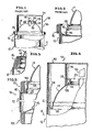
- Figure 1 is a fragmentary vertical sectional view taken through the upper part of a conventional serosol container and overcap.
- Figure 2 is an enlarged fragmentary vertical sectional view of the container of Figure 1, without the overcap, and showing the specifics of the connection between the body and the dome.
- Figure 3 is an enlarged fragmentary vertical sectional view with parts broken away of an aerosol container similar to that of Figure 2 having a separate bottom end and wherein both double seams are radially inwardly displaced in accordance with this invention.
- Figure 4 is a vertical sectional view of the upper part of the modified aerosol container having -attached thereto a different type of overcap.
- Figure 5 is an enlarged fragmentary sectional view taken through a modified deformation of the double seam.
- Referring now to the drawings in detail, it will be seen that there is illustrated in Figure 1 a standard aerosol container generally identified by the
numeral 10. Thecontainer 10 includes acontainer body 12 which may or may not have an integral bottom (not shown). Thecontainer body 12, as formed, has an open top or upper end, and this is closed by a conventional dome, generally identified by thenumeral 14. Thedome 14 is secured to thebody 12 by way of a conventionaldouble seam 16. - It is to be understood that in order for the
double seam 16 to be formed, the telescoped portions of the dome and the body must be supported by a conventional seaming chuck. Thus, the dome must have as a part of the double seam a chuck wall l8 which may be engaged by the seaming chuck. In order to provide thechuck wall 18 with clearance for the seaming chuck, it is necessary that thedome 14 be axially inwardly offset adjacent thechuck wall 18, thus defining anannular countersink 20. - The required provision of the
annular countersink 20 greatly reduces the buckling resistance of thedome 14 and has, in the past, required that thedome 14 be formed of thicker gauge metal than would otherwise be necessary to maintain the preselected internal pressure to which theaerosol container 10 is exposed. - In order further to describe the standard aerosol container, it is to be noted that the top part of the
dome 14 is provided with acentral opening 22 defined by an out-turned collar orcurl 24. Avalve cup 26 is seated in the opening and is provided with anannular portion 28 which interlocks and seals with thecollar 24. Thevalve cup 26 carries theusual dispensing valve 30. - Aerosol containers are conventionally provided with an overcap such as the
overcap 32. Theovercap 32 is of a cup-shaped configuration and includes anend wall 34 having depending therefrom askirt 36 which has its lower end locked generally within thecountersink 20. - At this time it is pointed out that the illustrated
countersink 20 has a lower portion which is narrower than anupper portion 38 and wherein, between the lower and upper portions, there is ashoulder 40 against which the lower end of theskirt 36 may seat. The exact details of the interlock of theskirt 36 with thedome 14 is not material as far as this invention is concerned. - In accordance with this invention, utilizing suitable reforming tooling, after the
dome 14 has been secured to thebody 12 by means of thedouble seam 16, thedouble seam 16 is radially inwardly deformed or necked-in so that all portions of thedouble seam 16 are disposed radially inwardly of thebody 12, as shown in the upper half of Figure 3. Thedouble seam 16 may thus be said to overlie a radially outer part of thecountersink 20 by effectively reducing the radial dimension of the countersink. The net result is that anupper portion 42 of thebody 12 is also displaced radially inwardly. - Significant strength improvement has been demonstrated with the
double seam 16 radially inwardly displaced as shown in Figure 3. However, if complete seam reduction is achieved as shown in Figure 5 wherein thedouble seam 16 completely closes thecountersink 20 and engages the dome profile as at 44, maximum strength improvement is obtained. - It has been found that there is an increased internal pressure resistance of the modified dome and double seam arrangements of Figures 3 and 5 which will permit the use of lighter gauge stock for the formation of the
dome 14. It is believed that the increased internal pressure resistance is provided by: - 1. A change in leverage applied to the countersink area through internal pressure by providing a negative countersink wall angle, as shown in Figure 5.
- 2. A reduction in radius of the unit at the bottom of the countersink area, as shown in Figures 3 and 5.
- 3. In the utlimate structure where the seam upper portion bears against the dome, a physical backup or restraint by the reduced diameter double seam.
- The necking in of the
double seam 16, as shown in Figure 3, with or without the additional tilting as shown in Figure 5, also has the benefit of the double seam being recessed within the outline of thebody 12 to provide for a tighter package of a plurality of containers. As pointed out above, thebody 12 may or may not have an integral bottom. In the lower portion of Figure 1, thecontainer 10 is illustrated with a separately formed bottom 46 which is secured to thebody 12 by a seconddouble seam 48. Thedouble seam 48 is beneficially formed in a radially outwardly directed position similar to that of thedouble seam 16 in the prior art showings of Figures 1 and 2 and thereafter is squeezed or forced radially inwardly as in the case of thedouble seam 16. - The
container 10 thus modified with all double seams disposed within the outline of thebody 12, may be readily packaged in a wraparound container to form a permanent type package, while at the same time requiring less material for the container. - When the
double seam 16 is necked-in as shown in Figure 3, or tilted as shown in Figure 5, theovercap 32 may be replaced by an overcap 50 (Figure 4) which may be of a conventional type. Theovercap 50 has anend wall 52 and a dependingskirt 54, theskirt 54 having an internal diameter corresponding to the outside diameter of thebody 12. - The
overcap 50 may be secured to the dome in one of two manners. At the present, overcaps of the type of which theovercap 50 is an example, are provided with aninner sleeve portion 56 with a lower radially inwardly directedenlargement 58 which interlocks beneath theannular portion 28 of the valve cup 26: On the other hand, it is feasible that theskirt 54 be provided at its lower end with a radially inwardly directed enlargement (not shown) which would lock below the lower part of thedouble seam 16. - Although only two preferred embodiments of the improved domed body double seam connection have been illustrated and described herein, it is to be understood that minor variations may be made in the container construction without departing from the spirit and scope of the invention as defined by the appended claims.
Claims (18)
1. An aerosol container of the type including a body having an open top closed by an aerosol dome secured to said body by a double seam, and wherein said dome has a part of said double seam a ch-uck wall surrounding an annular countersink for receiving a seaming chuck, characterised in that said double seam is reduced in diameter to overlie said annular countersink.
2. An aerosol container in accordance with claim 1 wherein said double seam at least substantially closes said annular countersink.
3. An aerosol container in accordance with claim lor 2 wherein said double seam engages said dome radially inwardly of said countersink and closes said annular countersink.
4. An aerosol container in accordance with claim l2 or 3 wherein said double seam is tilted radially inwardly.
5. An aerosol container according to any of claims 1 to 4 wherein said body immediately adjacent to and below said double seam is also deformed radially inwardly with said double seam being in its entirety recessed within the outline of said body.
6. An aerosol container according to any of claims 1 to 5 wherein said dome is formed of a lighter gauge metal as compared tc like size and pressurization unimproved aerosol containers.
7. An aerosol container according to any of claims 1 to 6 wherein there is an overcap for said dome said overcap having a skirt generally forming a continuation of said body.
8. A method improving the strength characteristics of a dome of an aerosol container wherein said container includes a body having an open top end closed by a dome secured to said body by a double seam, and wherein said dome has an annular countersink surrounding said double seam, characterised in that said method corpris- es squeezing said double seam radially inwardly to overlie said annular countersink and thereby strengthen said done.
9. A method according to claim 8 wherein said double seam is caused to be tilted.
10. A method according to claim 3 or 9 wherein said double seam is caused to be tilted and positioned to contact said dome above and radially inwardly of said annular countersink.
11. A method according to claim 10 wherein said body adjacent said double seam is also tilted radially inwardly to position said double seam radially inwardly of said body.
12. A method according to any of claims 8 to 11 wherein the squeezing of said double seam radially inwardly is primarily one of direct radial compression and said double seam is substantially cylindrical and coaxial with said body.
13. A container of the type comprising a body, a bottom end and a top end, and wherein at least one of said ends is formed separate and apart from said body and is secured to said body by a double seam projecting radially outwardly of said body, and all projecting double seams together within adjacent portions of said body and the respective ends are radially inwardly offset with all double seams between said body and said ends lying within axial extensions of said body.
14. A container according to claim 13 wherein said container is an aerosol container, said top end is in the form of a dome having an annular countersink immediately radially inwardly of said double seam for receiving a seaming chuck, and said double seam between said dome and said body at least partially overlies said countersink.
15. A container according to claim 13 or 14 wherein said radially inwardly offset double seam is substantially coaxial with said body.
16. A container according to claim 13,14 or 15 tilted radially inwardly and upwardly.
17. A container according to any of claims 13 to 16 wherein said end connected to said body by said double seam is said bottom end.
18. A container according to any of claims 1 to 7 and 13 to 17 wherein said countersink has a lower radius which is reduced when said double seam overlies said countersink.
Applications Claiming Priority (2)
| Application Number | Priority Date | Filing Date | Title |
|---|---|---|---|
| US531313 | 1983-09-12 | ||
| US06/531,313 US4775071A (en) | 1983-09-12 | 1983-09-12 | Strength aerosol dome |
Publications (1)
| Publication Number | Publication Date |
|---|---|
| EP0141513A1 true EP0141513A1 (en) | 1985-05-15 |
Family
ID=24117129
Family Applications (1)
| Application Number | Title | Priority Date | Filing Date |
|---|---|---|---|
| EP84306173A Withdrawn EP0141513A1 (en) | 1983-09-12 | 1984-09-10 | Improved strength aerosol dome |
Country Status (5)
| Country | Link |
|---|---|
| US (1) | US4775071A (en) |
| EP (1) | EP0141513A1 (en) |
| JP (1) | JPS6090166A (en) |
| AU (1) | AU3296984A (en) |
| CA (1) | CA1248890A (en) |
Families Citing this family (13)
| Publication number | Priority date | Publication date | Assignee | Title |
|---|---|---|---|---|
| DE29509207U1 (en) * | 1995-06-03 | 1995-08-24 | Carnaudmetalbox Sa | Sheet metal packaging container and manufacturing tool |
| US5704513A (en) * | 1995-07-25 | 1998-01-06 | Dispensing Containers Corporation | Thin walled cover for aerosol container and method of making same |
| US5636761A (en) * | 1995-10-16 | 1997-06-10 | Dispensing Containers Corporation | Deformation resistant aerosol container cover |
| EP0798232A1 (en) * | 1996-03-28 | 1997-10-01 | Alusuisse Technology & Management AG | One piece aluminium aerosol can |
| US6510967B1 (en) | 1999-06-29 | 2003-01-28 | Chase Products Company | Ergonomic aerosol dispensing system |
| AU4902401A (en) * | 1999-11-09 | 2001-06-25 | U.S. Can Company | Aerosol can having reduced diameter dome |
| US6318583B1 (en) * | 2000-03-14 | 2001-11-20 | United States Can Company | Beaded container |
| US6830419B1 (en) * | 2000-11-20 | 2004-12-14 | Alfons Haar Inc. | Aerosol can ends |
| ES2259094T3 (en) * | 2001-11-05 | 2006-09-16 | Corus Staal Bv | SUPERIOR CONE FOR A CAN OF AEROSOL, AND A CAN OF AEROSOL PROVIDED WITH THE SAME. |
| US7575133B2 (en) * | 2003-10-06 | 2009-08-18 | Crown Cork & Seal Technologies Corporation | Bi-can having internal bag |
| US8875936B2 (en) * | 2007-04-20 | 2014-11-04 | Rexam Beverage Can Company | Can end with negatively angled wall |
| US7591345B1 (en) * | 2007-11-05 | 2009-09-22 | Cummins Filtration Ip Inc. | Angled muffler seam construction and method |
| CN102219094B (en) * | 2011-04-28 | 2013-05-01 | 深圳华特容器股份有限公司 | Aerosol tank upper cover, molding method and die of upper cover back taper |
Citations (4)
| Publication number | Priority date | Publication date | Assignee | Title |
|---|---|---|---|---|
| FR2059222A5 (en) * | 1969-08-29 | 1971-05-28 | Alusuisse | |
| FR2143135A1 (en) * | 1971-06-22 | 1973-02-02 | Alusuisse | |
| LU69511A1 (en) * | 1974-02-28 | 1975-12-09 | ||
| EP0033912A1 (en) * | 1980-02-09 | 1981-08-19 | Blechwarenfabriken Züchner GmbH & Co. | Packaging container, particularly spray-can |
Family Cites Families (21)
| Publication number | Priority date | Publication date | Assignee | Title |
|---|---|---|---|---|
| US272921A (en) * | 1883-02-27 | tuckett | ||
| US700576A (en) * | 1902-02-03 | 1902-05-20 | Packer S Sanitary Can Company | Solderless end seam for tin cans. |
| AT11925B (en) * | 1902-02-24 | 1903-05-25 | Benjamin Adriance | |
| DE415933C (en) * | 1923-12-20 | 1925-07-03 | Kustner Freres Cie Sa | Method for closing packaging for goods of any consistency |
| CH172434A (en) * | 1933-12-23 | 1934-10-15 | Hirzel & Co S | Process for the production of a metal bottle and metal bottle produced by the process. |
| US2089185A (en) * | 1935-12-31 | 1937-08-10 | Henry F Colvin | Flexible container |
| US2322843A (en) * | 1940-01-31 | 1943-06-29 | Gerard C Deane | Combination container and cap remover |
| US2426550A (en) * | 1945-03-26 | 1947-08-26 | Continental Can Co | Beverage can |
| US2553559A (en) * | 1948-11-22 | 1951-05-22 | American Can Co | Compartment container assembly |
| US2775372A (en) * | 1953-08-06 | 1956-12-25 | Crown Cork & Seal Co | Protective cover for dispensing containers |
| US2771213A (en) * | 1953-11-25 | 1956-11-20 | James R Lewis | Stacking can |
| US3080989A (en) * | 1960-10-31 | 1963-03-12 | Dorset Rex Inc | Refillable holder for bottles and the like |
| US3416702A (en) * | 1966-03-13 | 1968-12-17 | Continental Can Co | Reinforced metallic container |
| US3700136A (en) * | 1966-03-25 | 1972-10-24 | Continental Can Co | End unit and liner for aerosol containers |
| US3987927A (en) * | 1971-07-08 | 1976-10-26 | Rheinpfalzische Blechemballagenfabrik G. Schonung & Co. Kg | Bead joint |
| CH559128A5 (en) * | 1972-12-04 | 1975-02-28 | Alusuisse | |
| US3942673A (en) * | 1974-05-10 | 1976-03-09 | National Can Corporation | Wall construction for containers |
| US4093102A (en) * | 1974-08-26 | 1978-06-06 | National Can Corporation | End panel for containers |
| US4106659A (en) * | 1976-07-01 | 1978-08-15 | General Motors Corporation | Pressure vessel |
| JPS5330165A (en) * | 1976-08-31 | 1978-03-22 | Sekisui Chem Co Ltd | Apparatus for purifying filthy water |
| US4361246A (en) * | 1980-12-17 | 1982-11-30 | Alexander Nelson | Container construction |
-
1983
- 1983-09-12 US US06/531,313 patent/US4775071A/en not_active Expired - Lifetime
-
1984
- 1984-09-10 EP EP84306173A patent/EP0141513A1/en not_active Withdrawn
- 1984-09-12 JP JP59191389A patent/JPS6090166A/en active Pending
- 1984-09-12 AU AU32969/84A patent/AU3296984A/en not_active Abandoned
- 1984-09-12 CA CA000462976A patent/CA1248890A/en not_active Expired
Patent Citations (4)
| Publication number | Priority date | Publication date | Assignee | Title |
|---|---|---|---|---|
| FR2059222A5 (en) * | 1969-08-29 | 1971-05-28 | Alusuisse | |
| FR2143135A1 (en) * | 1971-06-22 | 1973-02-02 | Alusuisse | |
| LU69511A1 (en) * | 1974-02-28 | 1975-12-09 | ||
| EP0033912A1 (en) * | 1980-02-09 | 1981-08-19 | Blechwarenfabriken Züchner GmbH & Co. | Packaging container, particularly spray-can |
Also Published As
| Publication number | Publication date |
|---|---|
| AU3296984A (en) | 1985-03-21 |
| US4775071A (en) | 1988-10-04 |
| JPS6090166A (en) | 1985-05-21 |
| CA1248890A (en) | 1989-01-17 |
Similar Documents
| Publication | Publication Date | Title |
|---|---|---|
| US10843845B2 (en) | Can shell and double-seamed can end | |
| US5149238A (en) | Pressure resistant sheet metal end closure | |
| EP0088968B1 (en) | A method for further forming a metal closure and a metal container end | |
| US3525455A (en) | Sheet metal container | |
| US7819275B2 (en) | Can shell and double-seamed can end | |
| US4577774A (en) | Buckle resistance for metal container closures | |
| US4809861A (en) | Buckle resistant can end | |
| US10865036B2 (en) | Beverage can having a grommet | |
| EP1237666B1 (en) | Can lid closure and method of joining a can lid closure to a can body | |
| US4775071A (en) | Strength aerosol dome | |
| US4790705A (en) | Method of forming a buckle resistant can end | |
| USRE33217E (en) | Buckle resistance for metal container closures | |
| ZA200602202B (en) | Can shell and double seamed can end | |
| US6428261B1 (en) | Method of forming a safety can end | |
| US3698596A (en) | Necked-in container | |
| GB2067159A (en) | Buckle-resistant container ends | |
| JP2942520B2 (en) | Substantially circular end seal lid used for substantially cylindrical containers | |
| EP0072252B1 (en) | Closure and container neck structure therefor | |
| JP2523678Y2 (en) | Aerosol can | |
| GB1588014A (en) | Container end wall |
Legal Events
| Date | Code | Title | Description |
|---|---|---|---|
| PUAI | Public reference made under article 153(3) epc to a published international application that has entered the european phase |
Free format text: ORIGINAL CODE: 0009012 |
|
| AK | Designated contracting states |
Designated state(s): AT BE CH DE FR GB IT LI LU NL SE |
|
| STAA | Information on the status of an ep patent application or granted ep patent |
Free format text: STATUS: THE APPLICATION IS DEEMED TO BE WITHDRAWN |
|
| 18D | Application deemed to be withdrawn |
Effective date: 19860116 |
|
| RIN1 | Information on inventor provided before grant (corrected) |
Inventor name: GIGGARD, EARL D. |