EP0141401A2 - Button orientation apparatus - Google Patents
Button orientation apparatus Download PDFInfo
- Publication number
- EP0141401A2 EP0141401A2 EP84113114A EP84113114A EP0141401A2 EP 0141401 A2 EP0141401 A2 EP 0141401A2 EP 84113114 A EP84113114 A EP 84113114A EP 84113114 A EP84113114 A EP 84113114A EP 0141401 A2 EP0141401 A2 EP 0141401A2
- Authority
- EP
- European Patent Office
- Prior art keywords
- button
- cam
- holder
- shaft
- die
- Prior art date
- Legal status (The legal status is an assumption and is not a legal conclusion. Google has not performed a legal analysis and makes no representation as to the accuracy of the status listed.)
- Granted
Links
Images


Classifications
-
- A—HUMAN NECESSITIES
- A44—HABERDASHERY; JEWELLERY
- A44B—BUTTONS, PINS, BUCKLES, SLIDE FASTENERS, OR THE LIKE
- A44B1/00—Buttons
-
- A—HUMAN NECESSITIES
- A41—WEARING APPAREL
- A41H—APPLIANCES OR METHODS FOR MAKING CLOTHES, e.g. FOR DRESS-MAKING OR FOR TAILORING, NOT OTHERWISE PROVIDED FOR
- A41H37/00—Machines, appliances or methods for setting fastener-elements on garments
- A41H37/10—Setting buttons
Definitions
- This invention relates to improvements in and relating to an apparatus for setting buttons or the like in the proper orientations on garments.
- buttons and their mating tacks are delivered successively from their respective chutes to a coacting punch and die assembly and are attached in coupling relation to a garment held between the punch and the die. If the button bears on its exposed surface indicia such as designs, letters, trademarks, etc., it is desired that the button be oriented to the proper position with respect to a predetermined reference point or line on the garment, or stated otherwise the manner in which the garment is worn.
- U.S. Patent 4,019,666, issued April 26, 1977 discloses a button orienting apparatus which includes a pusher mechanism for moving a button along a slide bracket until a tab on the reverse side of the button is caught by a pair of jaws on a locking lever mounted on the slide bracket.
- the pusher mechanism further moves the button until the latter is placed in a cylindrical gripping head.
- the gripping head with the button therein is turned through a predetermined angle.
- Such an angular movement of the gripping head is provided by a coacting rack and pinion.
- the pinion is connected to the gripping head by a coupling such as a universal joint, and the rack is reciprocatively driven by an air-pressurized cylinder.
- the gripping head functions as a setting die, the tendency is that the head becomes displaced axially and/or circumferentially due to impact by the punch.
- the coupling is provided to absorb and prevent such displacement of the gripping head from being transmitted to the pinion, but the coupling per se is susceptible to backlash which increases with torque and impact repeatedly imposed on the coupling, with the results that the gripping head fails to perform accurate angular orientation. Further, this frequent impact causes the coupling to be distorted at its bearings, making the gripping head inoperative.
- the stroke of the rack is relatively large to turn the pinion through a predetermined angle, and hence the stroke of the cylinder must be accordingly large enough, which means a prolonged length of time for the orientation of buttons.
- Japanese Patent Publication No. 59-11682 is directed to an improvement over the above prior art, and discloses a button orientation apparatus including a finger holder having a pair of fingers for gripping a button, the holder being vertically movably and rotatably mounted on a setting die.
- the finger holder is provided peripherally with a first gear engageable with a second gear which is adjustably driven by a cylinder mechanism.
- a cylindrical sleeve holder has a rotatable sleeve in which is journalled a rotative shaft. This shaft carries the above-mentioned gears on its upper end and a cam on its lower end.
- the sleeve has a means engageable with the cam for stopping the rotation of the shaft as the latter turns through predetermined angles.
- the orientation.of a button is determined by the amount of rotation of the shaft which is in turn determined by manually positioning a pin on the sleeve holder selectively in one of the apertures in the sleeve. This
- a button orientation apparatus characterized in that said apparatus comprises:
- the present invention seeks to provide a button orientation apparatus which will overcome the foregoing difficulties of the prior art and which incorporates structural features to enable speedy and accurate setting of buttons on garments.
- a button orientation apparatus which generally comprises a support frame 10, an elongate horizontal guide 11 mounted thereon for guidedly transporting buttons B one at a time from a chute 12 to a die unit 13, and a pusher 14 slidably mounted in a guide channel 15 in the guide 11 for pushing the button out of the guide 11 into the die unit 13.
- the button B has a disk-like head B 1 bearing a desired indicia and a tab B 2 .
- Designated at 16 is a friction member provided in the guide 11 and engageable with the peripheral edge of the button head B 1 to keep the button B in rotation until the tab B 2 is captured by the pusher.
- the button B is thereafter guided linearly toward the die unit 13.
- Such button feeding mechanisms are well known and form no positive part of the invention. Hence, no further details of this part of the apparatus will be required.
- the die unit 13 comprises a setting die 17 which coacts with a punch (not shown) to attach the button B to a garment (not shown) disposed between the die 17 and the punch as is well known in the art.
- the die 17 is secured at its lower end to a die holder 18 by means of a screw 19.
- the die holder 18, which is hollow at 19, is secured to the frame 10.
- a finger holder 20 is slidably and rotatably mounted on the die 17 and has on its lower periphery a ring gear 21.
- the finger holder 20 has at its upper end a flange 22 (Figure 2) integral therewith.
- a pair of clamping fingers 23,23 ( Figures 1, 2 and 5) are pivotally mounted on the flange 22 by means of a pair of pins 24,24, respectively, and are fitted in a pair of grooves 25,25 ( Figure 2) respectively formed in the flange 22.
- Each of the fingers 23 has on its upper end an inwardly directed projection 25 having an inclined bottom surface 26.
- An annular recess 27 extends horizontally in an inner surface of each finger projection 25.
- the fingers 23,23 are normally urged toward each other by means of springs 28,28, respectively.
- the finger holder 20 is normally urged upwardly by a compression spring 29.
- the button B transported by the pusher 14 is set in position on the die 17 with its peripheral flange portion fitted snugly in the annular recesses 27,27 of the confronting fingers 23,23.
- the die unit 13 is operatively connected with a drive unit 30.
- the drive unit 30 comprises a cylindrical shaft holder 31 secured to the frame 10 as at 32,32 and a rotary shaft 33 journalled in the holder 31 for rotation via bearings 34. Washers 35 are provided to hold the shaft 33 against vertical displacement relative to the holder 31.
- the shaft 33 has connected to its upper end a sector gear 36 which has a toothed periphery 37 extending through an aperture 38 in the die holder 18 into meshing engagement with the ring gear 21 of the finger holder 20.
- the shaft 33 is connected at its lower end to a cam assembly 39 and a connecting arm 40 underlying the assembly 39, as better shown in Figure 5.
- the cam assembly 39 which is rotative with the shaft 33, consists of a plurality of generally disc-shaped cam plates 41, 42 and 43 mounted in juxtaposed relation on and keyed to the rotary shaft 33 as at 44 in such relative positions that their respective engaging protuberances '41', 42' and 43' are displaced circumferentially a predetermined distance or stated otherwise held out of registry with respect to one another in the direction of rotation of the shaft 33 for purposes hereafter to be described.
- the connecting arm 40 is connected via a.link'45 to a piston rod 46 of a pneumatically operated cylinder 47.
- a pin holder 48 is secured at its upper portion to the shaft holder 31 by means of set screws 49 and has at its lower portion a plurality of apertures 50, 51 and 52 extending horizontally therethrough and registering in position with the cam plates 41, 42 and 43, respectively, as shown in Figure 1.
- the apertures 50, 51 and 52 are adapted to receive a stopper pin 53, only the aperture 50 being illustrated in engagement with the pin 53 to show one specific mode of operation.
- Designated at 54 is a set screw adapted to secure the pin 53 to the pin holder 48.
- the pin 53 has its probe end 53' extending into the path of rotative movement of the protuberance 41' of the cam plate 41. By manipulating the screw 54, however, the pin 53 may be retracted from the path of the cam plate 41, or the pin 53 may be transferred to the other aperture 51 or 52 depending upon the extent of orientation of the button B as later described.
- the cylinder 47 is pivotally connected by a support pin 55 to the frame 10 as shown in Figure 1, where its piston rod 46 is shown in forward stroke position in which the drive unit 30 is on standby. In this position, the apparatus may be operated where the button B need not be oriented.
- the piston rod 46 when handling buttons B that require orientation, the piston rod 46 is retracted from the position of Figure 1 in response to retraction of the pusher 14 which has carried the button B onto the setting die 17. Retracting the piston rod 46 causes the shaft 33 to rotate counterclockwise as viewed in Figure 2. This is accompanied by the rotation in the same direction of the sector gear 36 which is in meshing engagement with the gear 21 on the finger holder 20. The rotation of the shaft 33, hence the finger holder 20 terminates upon engagement of the stopper pin 53 with the protuberance 41' of the cam plate 41, whereupon the button B on the die 17 has been oriented in the proper position for setting onto a garment not shown.
- the angle of the rotation of the shaft 33 or the sector gear 36 may be varied at will by changing the operative position of the stopper pin 53 between the apertures 50, 51 and 52.
- the angle of the rotation or orientation of the button B is determined by a selected gear ratio of the sector gear 36 to the ring gear 21 and also determinable by the angle O 1 between each of the cam protuberances 41', 42', 43' and the stopper pin 53. Therefore, the angle of displacement 0 2 between cam protuberances 41', 42' and 43' may be selected such that the button B may be oriented desirably for angles of for instance 60 degrees, 120 degrees and 180 degrees, or 90 degrees, 180 degrees and 270 degrees, provided that the protuberances 41', 42' and 43' are equi-angularly spaced.
- FIG. 6 diagrammatically illustrates a cam control mechanism 56 employed according to the invention for effecting automatic control of the operation of the cam assembly 39.
- the control mechanism 56 comprises a plurality of plungers or other suitable actuators 57, 58 and 59 assigned to the stopper pins 53a, 53b and 53c, respectively, links 60, 61 and 62 connecting between respective plungers and respective stopper pins, and selector switches 63, 64 and 65 connected to plungers 57, 58 and 59, respectively.
- the switches 63, 64 and 65 may be selectively operated to take any one of the stopper pins 53a, 53b and 53c into or out of engagement with the corresponding cam (41, 42 or 43)..
Abstract
Description
- This invention relates to improvements in and relating to an apparatus for setting buttons or the like in the proper orientations on garments.
- Machines for attaching buttons or snap fasteners to a garment are known in which for instance buttons and their mating tacks are delivered successively from their respective chutes to a coacting punch and die assembly and are attached in coupling relation to a garment held between the punch and the die. If the button bears on its exposed surface indicia such as designs, letters, trademarks, etc., it is desired that the button be oriented to the proper position with respect to a predetermined reference point or line on the garment, or stated otherwise the manner in which the garment is worn.
- U.S. Patent 4,019,666, issued April 26, 1977, discloses a button orienting apparatus which includes a pusher mechanism for moving a button along a slide bracket until a tab on the reverse side of the button is caught by a pair of jaws on a locking lever mounted on the slide bracket. The pusher mechanism further moves the button until the latter is placed in a cylindrical gripping head. Then, the gripping head with the button therein is turned through a predetermined angle. Such an angular movement of the gripping head is provided by a coacting rack and pinion. The pinion is connected to the gripping head by a coupling such as a universal joint, and the rack is reciprocatively driven by an air-pressurized cylinder. Since the gripping head functions as a setting die, the tendency is that the head becomes displaced axially and/or circumferentially due to impact by the punch. The coupling is provided to absorb and prevent such displacement of the gripping head from being transmitted to the pinion, but the coupling per se is susceptible to backlash which increases with torque and impact repeatedly imposed on the coupling, with the results that the gripping head fails to perform accurate angular orientation. Further, this frequent impact causes the coupling to be distorted at its bearings, making the gripping head inoperative. Moreover, the stroke of the rack is relatively large to turn the pinion through a predetermined angle, and hence the stroke of the cylinder must be accordingly large enough, which means a prolonged length of time for the orientation of buttons.
- Japanese Patent Publication No. 59-11682 is directed to an improvement over the above prior art, and discloses a button orientation apparatus including a finger holder having a pair of fingers for gripping a button, the holder being vertically movably and rotatably mounted on a setting die. The finger holder is provided peripherally with a first gear engageable with a second gear which is adjustably driven by a cylinder mechanism. A cylindrical sleeve holder has a rotatable sleeve in which is journalled a rotative shaft. This shaft carries the above-mentioned gears on its upper end and a cam on its lower end. The sleeve has a means engageable with the cam for stopping the rotation of the shaft as the latter turns through predetermined angles. The orientation.of a button is determined by the amount of rotation of the shaft which is in turn determined by manually positioning a pin on the sleeve holder selectively in one of the apertures in the sleeve. This operation Is. rather complicated and tedious.
- According to the invention, there is provided a button orientation apparatus characterized in that said apparatus comprises:
- (a) a support frame;
- (b) a setting die secured to said support for receiving a button thereon;
- (c) a finger holder rotatably and axially movably mounted on said setting die and having at its upper end a pair of clamping fingers for clamping the button on said setting die and having on its lower periphery a ring gear for rotating the finger holder;
- (d) a shaft holder secured to said frame;
- (e) a rotary shaft jurnalled in said shaft holder for rotation and having at its upper end a sector gear in meshing engagement with said ring gear;
- (f) a cam assembly rotatively connected to the lower end of said shaft and having a plurality of cam plates in juxtaposed relation;
- (g) a pin holder secured to said shaft holder and having a plurality of apertures registering in position respectively with said cam plates and a stopper pin releasably received in one of said apertures; and
- (h) a cylinder and piston drive for driving said rotary shaft.
- The present invention seeks to provide a button orientation apparatus which will overcome the foregoing difficulties of the prior art and which incorporates structural features to enable speedy and accurate setting of buttons on garments.
- Many other advantages and features of the present invention will become manifest to those versed in the art upon making reference to the detailed description and the accompanying sheets of drawings in which a preferred structural embodiment incorporating the principles of the present invention is shown by way of illustrative example.
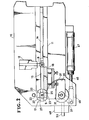
- Figure 1 is a fragmentary side elevational view of a button orientation apparatus according to the invention;
- Figure 2 is a fragmentary plan view of the apparatus of Figure 1;
- Figure 3 is a fragmentary bottom view of the apparatus;
- Figure 4 is a fragmentary front view of the apparatus;
- Figure 5 is a cross-sectional view taken on the line V-V of Figure 1; and
- ' Figure 6 is a diagrammatic view illustrating a cam control mechanism employed in accordance with the invention.
- Referring to Figures 1 and 2, there is shown a button orientation apparatus which generally comprises a
support frame 10, an elongatehorizontal guide 11 mounted thereon for guidedly transporting buttons B one at a time from achute 12 to adie unit 13, and apusher 14 slidably mounted in aguide channel 15 in theguide 11 for pushing the button out of theguide 11 into thedie unit 13. The button B has a disk-like head B1 bearing a desired indicia and a tab B2. - Designated at 16 is a friction member provided in the
guide 11 and engageable with the peripheral edge of the button head B1 to keep the button B in rotation until the tab B2 is captured by the pusher. The button B is thereafter guided linearly toward the dieunit 13. Such button feeding mechanisms are well known and form no positive part of the invention. Hence, no further details of this part of the apparatus will be required. - As better shown in Figure 5, the
die unit 13 comprises asetting die 17 which coacts with a punch (not shown) to attach the button B to a garment (not shown) disposed between thedie 17 and the punch as is well known in the art. The die 17 is secured at its lower end to adie holder 18 by means of ascrew 19. The dieholder 18, which is hollow at 19, is secured to theframe 10. Afinger holder 20 is slidably and rotatably mounted on thedie 17 and has on its lower periphery aring gear 21. Thefinger holder 20 has at its upper end a flange 22 (Figure 2) integral therewith. A pair ofclamping fingers 23,23 (Figures 1, 2 and 5) are pivotally mounted on theflange 22 by means of a pair ofpins grooves 25,25 (Figure 2) respectively formed in theflange 22. Each of thefingers 23 has on its upper end an inwardly directedprojection 25 having aninclined bottom surface 26. An annular recess 27 extends horizontally in an inner surface of eachfinger projection 25. Thefingers springs finger holder 20 is normally urged upwardly by acompression spring 29. - The button B transported by the
pusher 14 is set in position on thedie 17 with its peripheral flange portion fitted snugly in the annular recesses 27,27 of the confrontingfingers - The die
unit 13 is operatively connected with adrive unit 30. Thedrive unit 30 comprises acylindrical shaft holder 31 secured to theframe 10 as at 32,32 and arotary shaft 33 journalled in theholder 31 for rotation viabearings 34.Washers 35 are provided to hold theshaft 33 against vertical displacement relative to theholder 31. Theshaft 33 has connected to its upper end asector gear 36 which has atoothed periphery 37 extending through anaperture 38 in thedie holder 18 into meshing engagement with thering gear 21 of thefinger holder 20. Theshaft 33 is connected at its lower end to acam assembly 39 and a connectingarm 40 underlying theassembly 39, as better shown in Figure 5. - The
cam assembly 39, which is rotative with theshaft 33, consists of a plurality of generally disc-shaped cam plates rotary shaft 33 as at 44 in such relative positions that their respective engaging protuberances '41', 42' and 43' are displaced circumferentially a predetermined distance or stated otherwise held out of registry with respect to one another in the direction of rotation of theshaft 33 for purposes hereafter to be described. - The connecting
arm 40 is connected via a.link'45 to apiston rod 46 of a pneumatically operatedcylinder 47. - A
pin holder 48 is secured at its upper portion to theshaft holder 31 by means of setscrews 49 and has at its lower portion a plurality ofapertures cam plates apertures stopper pin 53, only theaperture 50 being illustrated in engagement with thepin 53 to show one specific mode of operation. Designated at 54 is a set screw adapted to secure thepin 53 to thepin holder 48. In the illustrated embodiment, thepin 53 has its probe end 53' extending into the path of rotative movement of the protuberance 41' of thecam plate 41. By manipulating thescrew 54, however, thepin 53 may be retracted from the path of thecam plate 41, or thepin 53 may be transferred to theother aperture - The
cylinder 47 is pivotally connected by asupport pin 55 to theframe 10 as shown in Figure 1, where itspiston rod 46 is shown in forward stroke position in which thedrive unit 30 is on standby. In this position, the apparatus may be operated where the button B need not be oriented. - Now, when handling buttons B that require orientation, the
piston rod 46 is retracted from the position of Figure 1 in response to retraction of thepusher 14 which has carried the button B onto the setting die 17. Retracting thepiston rod 46 causes theshaft 33 to rotate counterclockwise as viewed in Figure 2. This is accompanied by the rotation in the same direction of thesector gear 36 which is in meshing engagement with thegear 21 on thefinger holder 20. The rotation of theshaft 33, hence thefinger holder 20 terminates upon engagement of thestopper pin 53 with the protuberance 41' of thecam plate 41, whereupon the button B on thedie 17 has been oriented in the proper position for setting onto a garment not shown. - Actuating the
cylinder 47 to make a forward stroke of thepiston rod 46 back to the position of Figure 1 or Figure 2, causes theshaft 33 and hence thefinger holder 17 to rotate clockwise back into the original position in which the clampingfingers - The angle of the rotation of the
shaft 33 or thesector gear 36 may be varied at will by changing the operative position of thestopper pin 53 between theapertures - The angle of the rotation or orientation of the button B is determined by a selected gear ratio of the
sector gear 36 to thering gear 21 and also determinable by the angle O1 between each of the cam protuberances 41', 42', 43' and thestopper pin 53. Therefore, the angle of displacement 02 between cam protuberances 41', 42' and 43' may be selected such that the button B may be oriented desirably for angles of forinstance 60 degrees, 120 degrees and 180 degrees, or 90 degrees, 180 degrees and 270 degrees, provided that the protuberances 41', 42' and 43' are equi-angularly spaced. - Figure 6 diagrammatically illustrates a
cam control mechanism 56 employed according to the invention for effecting automatic control of the operation of thecam assembly 39. Thecontrol mechanism 56 comprises a plurality of plungers or othersuitable actuators plungers switches
Claims (4)
Applications Claiming Priority (2)
| Application Number | Priority Date | Filing Date | Title |
|---|---|---|---|
| JP171118/83U | 1983-11-04 | ||
| JP1983171118U JPS6078826U (en) | 1983-11-04 | 1983-11-04 | Direction setting device in button mounting machine |
Publications (3)
| Publication Number | Publication Date |
|---|---|
| EP0141401A2 true EP0141401A2 (en) | 1985-05-15 |
| EP0141401A3 EP0141401A3 (en) | 1987-09-30 |
| EP0141401B1 EP0141401B1 (en) | 1989-10-04 |
Family
ID=15917309
Family Applications (1)
| Application Number | Title | Priority Date | Filing Date |
|---|---|---|---|
| EP84113114A Expired EP0141401B1 (en) | 1983-11-04 | 1984-10-31 | Button orientation apparatus |
Country Status (8)
| Country | Link |
|---|---|
| US (1) | US4592501A (en) |
| EP (1) | EP0141401B1 (en) |
| JP (1) | JPS6078826U (en) |
| KR (1) | KR860000961Y1 (en) |
| AU (1) | AU550739B2 (en) |
| CA (1) | CA1232567A (en) |
| DE (1) | DE3479957D1 (en) |
| ES (1) | ES537305A0 (en) |
Cited By (2)
| Publication number | Priority date | Publication date | Assignee | Title |
|---|---|---|---|---|
| EP0471970A1 (en) * | 1990-08-20 | 1992-02-26 | Schaeffer GmbH | Method for orienting and fastening buttons, rivets or the like, especially to clothing |
| CN104646562A (en) * | 2014-12-29 | 2015-05-27 | 深圳市联星服装辅料有限公司 | Button trimming machine |
Families Citing this family (8)
| Publication number | Priority date | Publication date | Assignee | Title |
|---|---|---|---|---|
| DE3501224A1 (en) * | 1985-01-16 | 1986-07-17 | William Prym-Werke GmbH & Co KG, 5190 Stolberg | RIVET PRESS FOR FASTENING A CLOSING FUNCTION PART, IN PARTICULAR PUSH BUTTON PART, ON A CARRIER SHEET, LIKE A CLOTHING PIECE |
| JPH0630746Y2 (en) * | 1985-10-26 | 1994-08-17 | 吉田工業株式会社 | Stopper parts transportation device for buttons |
| DE3822519A1 (en) * | 1988-07-04 | 1990-01-11 | Prym Werke William | DEVICE FOR ANGLED RIGHT POSITIONING OF A HARD TOOL ITEM, LIKE A BUTTON OD. THE LIKE, IN THE TOOL OF A PUTTING MACHINE |
| JP2614958B2 (en) * | 1991-12-25 | 1997-05-28 | ワイケイケイ株式会社 | Button transfer device for button mounting machine |
| JP2731061B2 (en) * | 1991-12-25 | 1998-03-25 | ワイケイケイ株式会社 | Button transport unit of button mounting machine |
| JP4080281B2 (en) * | 2002-09-10 | 2008-04-23 | Ykk株式会社 | Button positioning device for button mounting machine |
| CN103263097B (en) * | 2013-05-15 | 2015-04-08 | 宁波三合鑫自动化有限公司 | Motor direct drive cam connection rod type automatic button feeding device and method |
| WO2018198358A1 (en) * | 2017-04-28 | 2018-11-01 | Ykk株式会社 | Button attachment member conveying device |
Citations (2)
| Publication number | Priority date | Publication date | Assignee | Title |
|---|---|---|---|---|
| US2878954A (en) * | 1956-01-18 | 1959-03-24 | Scovill Manufacturing Co | Button registering machines |
| US4019666A (en) * | 1975-11-10 | 1977-04-26 | Scovill Manufacturing Company | Fastener attaching machine having means for orienting caps, buttons, and the like |
Family Cites Families (5)
| Publication number | Priority date | Publication date | Assignee | Title |
|---|---|---|---|---|
| US3400442A (en) * | 1966-07-25 | 1968-09-10 | Vernco Corp | Work orienter |
| JPS5254539U (en) * | 1975-10-18 | 1977-04-19 | ||
| JPS5911682B2 (en) * | 1981-07-03 | 1984-03-17 | ワイケイケイ株式会社 | Direction setting device in button mounting machine |
| JPS5911682A (en) * | 1982-07-13 | 1984-01-21 | Citizen Watch Co Ltd | Semiconductor nonvolatile storage device |
| US4493448A (en) * | 1983-01-17 | 1985-01-15 | Yoshida Kogyo K.K. | Apparatus for orienting and placing a button for attachment to a garment |
-
1983
- 1983-11-04 JP JP1983171118U patent/JPS6078826U/en active Granted
-
1984
- 1984-09-28 AU AU33709/84A patent/AU550739B2/en not_active Ceased
- 1984-10-12 CA CA000465276A patent/CA1232567A/en not_active Expired
- 1984-10-27 KR KR2019840010702U patent/KR860000961Y1/en not_active IP Right Cessation
- 1984-10-31 DE DE8484113114T patent/DE3479957D1/en not_active Expired
- 1984-10-31 EP EP84113114A patent/EP0141401B1/en not_active Expired
- 1984-11-02 ES ES84537305A patent/ES537305A0/en active Granted
- 1984-11-02 US US06/667,752 patent/US4592501A/en not_active Expired - Fee Related
Patent Citations (3)
| Publication number | Priority date | Publication date | Assignee | Title |
|---|---|---|---|---|
| US2878954A (en) * | 1956-01-18 | 1959-03-24 | Scovill Manufacturing Co | Button registering machines |
| US4019666A (en) * | 1975-11-10 | 1977-04-26 | Scovill Manufacturing Company | Fastener attaching machine having means for orienting caps, buttons, and the like |
| US4019666B1 (en) * | 1975-11-10 | 1984-12-04 |
Cited By (2)
| Publication number | Priority date | Publication date | Assignee | Title |
|---|---|---|---|---|
| EP0471970A1 (en) * | 1990-08-20 | 1992-02-26 | Schaeffer GmbH | Method for orienting and fastening buttons, rivets or the like, especially to clothing |
| CN104646562A (en) * | 2014-12-29 | 2015-05-27 | 深圳市联星服装辅料有限公司 | Button trimming machine |
Also Published As
| Publication number | Publication date |
|---|---|
| KR860000961Y1 (en) | 1986-05-23 |
| AU3370984A (en) | 1985-05-09 |
| EP0141401B1 (en) | 1989-10-04 |
| ES8507071A1 (en) | 1985-09-16 |
| EP0141401A3 (en) | 1987-09-30 |
| CA1232567A (en) | 1988-02-09 |
| JPS6329719Y2 (en) | 1988-08-09 |
| JPS6078826U (en) | 1985-06-01 |
| ES537305A0 (en) | 1985-09-16 |
| AU550739B2 (en) | 1986-04-10 |
| US4592501A (en) | 1986-06-03 |
| DE3479957D1 (en) | 1989-11-09 |
| KR850007929U (en) | 1985-10-26 |
Similar Documents
| Publication | Publication Date | Title |
|---|---|---|
| CA1232567A (en) | Button orientation apparatus | |
| DE3822519A1 (en) | DEVICE FOR ANGLED RIGHT POSITIONING OF A HARD TOOL ITEM, LIKE A BUTTON OD. THE LIKE, IN THE TOOL OF A PUTTING MACHINE | |
| US3675302A (en) | Automatic assembly machine | |
| DE3324715C2 (en) | ||
| EP0063366B1 (en) | Button orienting and placing apparatus | |
| EP0381226B1 (en) | Apparatus for protecting light projector from collision with punch of button setting machine | |
| DE2038505C3 (en) | Missing stitch mechanism for sewing machines | |
| US3069688A (en) | Fastener setting machine | |
| GB2152866A (en) | Button orientation apparatus | |
| US4493448A (en) | Apparatus for orienting and placing a button for attachment to a garment | |
| CA2008469C (en) | Stroke adjustment apparatus for light projector of button setting machine | |
| DE3519849C1 (en) | Blindstitch sewing machine | |
| CA1206811A (en) | Apparatus for orienting and placing a button for attachment to a garment | |
| DE2921349C2 (en) | Pattern selection device of a zigzag sewing machine | |
| DE2613089B2 (en) | Sewing machine with a device for producing individual basting stitches | |
| EP0113791B1 (en) | Apparatus for orienting and placing a button for attachment to a garment | |
| GB2138453A (en) | Apparatus for attaching fastener elements onto a garment | |
| DE3134028C2 (en) | Feed device for an automatic sewing machine | |
| US3879587A (en) | Blender apparatus having manual preset timer actuating device | |
| JPS5911682B2 (en) | Direction setting device in button mounting machine | |
| US4899673A (en) | Control device for cyclic sewing machine | |
| DE3626761C1 (en) | Sewing unit | |
| GB2133670A (en) | Apparatus for orienting and placing a button for attachment to a garment | |
| DE620661C (en) | Stop device for buttonhole sewing machines | |
| GB2178453A (en) | Buttonholer for zigzag sewing machine |
Legal Events
| Date | Code | Title | Description |
|---|---|---|---|
| PUAI | Public reference made under article 153(3) epc to a published international application that has entered the european phase |
Free format text: ORIGINAL CODE: 0009012 |
|
| AK | Designated contracting states |
Designated state(s): BE CH DE FR IT LI NL SE |
|
| PUAL | Search report despatched |
Free format text: ORIGINAL CODE: 0009013 |
|
| AK | Designated contracting states |
Kind code of ref document: A3 Designated state(s): BE CH DE FR IT LI NL SE |
|
| 17P | Request for examination filed |
Effective date: 19871218 |
|
| 17Q | First examination report despatched |
Effective date: 19880427 |
|
| GRAA | (expected) grant |
Free format text: ORIGINAL CODE: 0009210 |
|
| AK | Designated contracting states |
Kind code of ref document: B1 Designated state(s): BE CH DE FR IT LI NL SE |
|
| ITF | It: translation for a ep patent filed |
Owner name: JACOBACCI & PERANI S.P.A. |
|
| ET | Fr: translation filed | ||
| REF | Corresponds to: |
Ref document number: 3479957 Country of ref document: DE Date of ref document: 19891109 |
|
| PLBE | No opposition filed within time limit |
Free format text: ORIGINAL CODE: 0009261 |
|
| STAA | Information on the status of an ep patent application or granted ep patent |
Free format text: STATUS: NO OPPOSITION FILED WITHIN TIME LIMIT |
|
| 26N | No opposition filed | ||
| ITTA | It: last paid annual fee | ||
| PGFP | Annual fee paid to national office [announced via postgrant information from national office to epo] |
Ref country code: BE Payment date: 19940715 Year of fee payment: 11 |
|
| PGFP | Annual fee paid to national office [announced via postgrant information from national office to epo] |
Ref country code: FR Payment date: 19940923 Year of fee payment: 11 |
|
| PGFP | Annual fee paid to national office [announced via postgrant information from national office to epo] |
Ref country code: CH Payment date: 19941013 Year of fee payment: 11 |
|
| PGFP | Annual fee paid to national office [announced via postgrant information from national office to epo] |
Ref country code: SE Payment date: 19941031 Year of fee payment: 11 Ref country code: NL Payment date: 19941031 Year of fee payment: 11 Ref country code: DE Payment date: 19941031 Year of fee payment: 11 |
|
| EAL | Se: european patent in force in sweden |
Ref document number: 84113114.7 |
|
| PG25 | Lapsed in a contracting state [announced via postgrant information from national office to epo] |
Ref country code: LI Effective date: 19951031 Ref country code: CH Effective date: 19951031 Ref country code: BE Effective date: 19951031 |
|
| PG25 | Lapsed in a contracting state [announced via postgrant information from national office to epo] |
Ref country code: SE Effective date: 19951101 |
|
| BERE | Be: lapsed |
Owner name: NIPPON NOTION KOGYO CO. LTD Effective date: 19951031 |
|
| PG25 | Lapsed in a contracting state [announced via postgrant information from national office to epo] |
Ref country code: NL Effective date: 19960501 |
|
| REG | Reference to a national code |
Ref country code: CH Ref legal event code: PL |
|
| PG25 | Lapsed in a contracting state [announced via postgrant information from national office to epo] |
Ref country code: FR Effective date: 19960628 |
|
| PG25 | Lapsed in a contracting state [announced via postgrant information from national office to epo] |
Ref country code: DE Effective date: 19960702 |
|
| NLV4 | Nl: lapsed or anulled due to non-payment of the annual fee |
Effective date: 19960501 |
|
| EUG | Se: european patent has lapsed |
Ref document number: 84113114.7 |
|
| REG | Reference to a national code |
Ref country code: FR Ref legal event code: ST |