EP0141399A2 - Humidifier, particularly for pulmonary assistance systems - Google Patents
Humidifier, particularly for pulmonary assistance systems Download PDFInfo
- Publication number
- EP0141399A2 EP0141399A2 EP84113073A EP84113073A EP0141399A2 EP 0141399 A2 EP0141399 A2 EP 0141399A2 EP 84113073 A EP84113073 A EP 84113073A EP 84113073 A EP84113073 A EP 84113073A EP 0141399 A2 EP0141399 A2 EP 0141399A2
- Authority
- EP
- European Patent Office
- Prior art keywords
- reservoir
- water
- humidifier
- housing
- air passage
- Prior art date
- Legal status (The legal status is an assumption and is not a legal conclusion. Google has not performed a legal analysis and makes no representation as to the accuracy of the status listed.)
- Granted
Links
Images

Classifications
-
- A—HUMAN NECESSITIES
- A61—MEDICAL OR VETERINARY SCIENCE; HYGIENE
- A61M—DEVICES FOR INTRODUCING MEDIA INTO, OR ONTO, THE BODY; DEVICES FOR TRANSDUCING BODY MEDIA OR FOR TAKING MEDIA FROM THE BODY; DEVICES FOR PRODUCING OR ENDING SLEEP OR STUPOR
- A61M16/00—Devices for influencing the respiratory system of patients by gas treatment, e.g. mouth-to-mouth respiration; Tracheal tubes
- A61M16/10—Preparation of respiratory gases or vapours
- A61M16/14—Preparation of respiratory gases or vapours by mixing different fluids, one of them being in a liquid phase
- A61M16/16—Devices to humidify the respiration air
-
- A—HUMAN NECESSITIES
- A61—MEDICAL OR VETERINARY SCIENCE; HYGIENE
- A61M—DEVICES FOR INTRODUCING MEDIA INTO, OR ONTO, THE BODY; DEVICES FOR TRANSDUCING BODY MEDIA OR FOR TAKING MEDIA FROM THE BODY; DEVICES FOR PRODUCING OR ENDING SLEEP OR STUPOR
- A61M16/00—Devices for influencing the respiratory system of patients by gas treatment, e.g. mouth-to-mouth respiration; Tracheal tubes
- A61M16/0096—High frequency jet ventilation
-
- A—HUMAN NECESSITIES
- A61—MEDICAL OR VETERINARY SCIENCE; HYGIENE
- A61M—DEVICES FOR INTRODUCING MEDIA INTO, OR ONTO, THE BODY; DEVICES FOR TRANSDUCING BODY MEDIA OR FOR TAKING MEDIA FROM THE BODY; DEVICES FOR PRODUCING OR ENDING SLEEP OR STUPOR
- A61M16/00—Devices for influencing the respiratory system of patients by gas treatment, e.g. mouth-to-mouth respiration; Tracheal tubes
- A61M16/10—Preparation of respiratory gases or vapours
- A61M16/14—Preparation of respiratory gases or vapours by mixing different fluids, one of them being in a liquid phase
- A61M16/16—Devices to humidify the respiration air
- A61M16/162—Water-reservoir filling system, e.g. automatic
-
- A—HUMAN NECESSITIES
- A61—MEDICAL OR VETERINARY SCIENCE; HYGIENE
- A61M—DEVICES FOR INTRODUCING MEDIA INTO, OR ONTO, THE BODY; DEVICES FOR TRANSDUCING BODY MEDIA OR FOR TAKING MEDIA FROM THE BODY; DEVICES FOR PRODUCING OR ENDING SLEEP OR STUPOR
- A61M2205/00—General characteristics of the apparatus
- A61M2205/12—General characteristics of the apparatus with interchangeable cassettes forming partially or totally the fluid circuit
-
- Y—GENERAL TAGGING OF NEW TECHNOLOGICAL DEVELOPMENTS; GENERAL TAGGING OF CROSS-SECTIONAL TECHNOLOGIES SPANNING OVER SEVERAL SECTIONS OF THE IPC; TECHNICAL SUBJECTS COVERED BY FORMER USPC CROSS-REFERENCE ART COLLECTIONS [XRACs] AND DIGESTS
- Y10—TECHNICAL SUBJECTS COVERED BY FORMER USPC
- Y10S—TECHNICAL SUBJECTS COVERED BY FORMER USPC CROSS-REFERENCE ART COLLECTIONS [XRACs] AND DIGESTS
- Y10S261/00—Gas and liquid contact apparatus
- Y10S261/54—Venturi scrubbers
Definitions
- the present invention relates to a humidifer and more particularly to a humidifier especially adapted for use in pulmonary assistance systems.
- the gas volume within the humidifier must be limited to ensure transmission of the high frequency pulses through the humidifier. If the gas volume within the humidifier exceeds a certain level, the high frequency pulses will be damped out within the humidifier rather than being transmitted to the patient. In addition, high frequency ventilation necessitates the use of higher pressures than occur at normal ventilation, so the humidifer apparatus must be a pressure vessel. The prior known devices generally do not meet these requirements and are, therefore, not suitable for use with high frequency ventilation systems.
- the present invention provides a humidifier for pulmonary assistance systems and utilizes the principle of a jet pump to draw water from a reservoir and entrain it as vapor in air flowing through the apparatus.
- a collection surface is provided for extracting droplets of water from the air flow and returning them to the reservoir.
- the humidifier is packaged in a transparent housing which includes a heating panel to enhance the vaporization of the water and to permit visual observation of the humidifying process to ensure proper function of the apparatus.
- a reservoir 19 is formed centrally in the housing and is supplied with water through a connection 20 and channel 20a in the upstream end of the housing.
- the upper portion of the reservoir is open to a portion of the air passage 14 so that the surface of the water is exposed to the pressure of the air therewithin.
- the pressure differential between the surface of the water in the reservoir and the throat 16, combined with the aspirating effect of the air flow past the end of a channel 21, causes water to flow from the reservoir, through the channel 21, into the throat.
- the position of the venturi section below the water level in the reservoir facilitates water pick up in a pulsing mode.
- the water discharged from channel 21 into the rapidly moving air flow in the throat is entrained in the flow and largely vaporized.
- the divergent segment 17 discharges into an enlarged scrubbing area 22 which extends over the length of the reservoir along its upper edge.
- a series of vanes 23 and 24 extend across the scrubbing area from the upper edge of the housing to the upper edge of the reservoir and are angled approximately 30° in the direction of air flow. Alternate vanes are formed on the front and back sections of the housing as shown in the drawings to provide a sinuous path through the area 22. As the air flows through the scrubbing area, it strikes the vanes 23, 24, etc., which serve as collection surfaces. As the air flows through the scrubbing area, the droplets of water are propelled against the vanes and will collect thereon.
- vanes Due to the angular position of the vanes, the momentum of the air stream against the collected droplets forces them to move down the vanes and drop back into the reservoir faster than the gravity pull.
- the number of vanes and spacing between them are chosen such that all of the entrained droplets are cleared from the air flow before it is discharged through outlet 25 at the downstream end of the housing.
- the air passage 14 through the housing is configured such that the venturi section is located below the water level in the reservoir and the discharge from the divergent segment 17 is vectored away form the reservoir.
- the location of the venturi ensures that water will always be present at the throat 16 for entrainment in either a continuous or pulsing mode of operation.
- Vectoring the discharge from the divergent segment against the housing (vanes) rather than against the reservoir prevents formation of waves on the surface of the water in the reservoir which would cause entrainment of water droplets within the scrubbing area and consequent spitting at the outlet 25.
- a lateral wall of the reservoir 19 on the back section 13 is formed by a flat cup 26 made of heat conductive material, such as aluminum, copper, etc., which is retained in sealing relation within an opening 27 in the section by means on an O-ring 28.
- the water within the reservoir is heated by application of heat to the cup 26.
- the water level in the reservoir 19 is sensed by a sensor which includes electrically conductive pins 29, 30 and 31 which extend through the back section of the housing into the reservoir and are spaced to detect half-full and full conditions in the reservoir.
- the half-full indication is detected when water covers pins 30 and 31 to, for example, close a circuit, and is used to prevent application of heat to the reservoir until it is half filled with water.
- the full level indication is detected when water covers pins 29 and 30, and is used to signal a water supply pump to pump water into the reservoir against the pressure within the housing to thereby maintain the water level at the desired point.
- the heater will operate at optimum efficiency and the gas volume within the housing will be maintained at some predetermined level, advantageously between .5 and 1.5 cubic inches.
- a temperature sensor 32 is installed in the scrubbing area close to the outlet 25 to sense the temperature of the air flow so that the heater can be regulated to maintain the water at the desired temperature with different rates of air flow.
- the sensor could be a conventional thermocouple temperature sensing device.
- the front and back sections of the housing can be molded of clear plastic in an injection molding machine.
- the grooves and recesses in the facing surfaces of the front and back sections match with one another to define the various openings, passages, etc. when the sections are joined.
- the metal cup 26 can be stamped from sheet material and pushed into place in the back section before the two sections are joined. The manufacture and assembly is simple and inexpensive, so that the humidifier can be discarded after use instead of being disassembled and sterilized.
- the humidifier apparatus can be mounted on a control box with the aid of two guide pins received in openings 33 and 34 in the opposite ends of the housing. Latches can be utilized to hold the housing in place on the pins. The cup 26 on the back of the housing presses against a spring-loaded heater plate for good thermal contact. When the latches are released, the used humidifier can be removed from the pins. A new one is installed by placing the housing on the pins and pressing down until the latches snap in place.
- the present humidifier can operate continuously or intermittently, as desired, can produce humid air in small quantities, and removes the entrained water droplets so that the moisture is delivered only in the form of water vapor.
- the transparent housing permits the function of the humidifier to be visually checked during the operation to detect any problems which might occur.
Abstract

Description
- The present invention relates to a humidifer and more particularly to a humidifier especially adapted for use in pulmonary assistance systems.
- In pulmonary assistance systems wherein air, oxygen and/or medication are supplied to augment or enhance a patient's normal breathing, it often becomes desirable to add moisture to the air supplied to the patient. Heretofore, this has been accomplished by channeling the air being supplied past a container of water. The container is heated to raise the temperature of the water to increase the vaporization and the air is then passed over the water or a water-filled curtain, such as a wick, and water vapor is entrained in the air flow. Such devices have been designed for use at low pressures and at normal breathing rates and have been relatively large to meet the breathing needs of the user. In assistance systems which utilize a rapid sequence of short pulses of pressurized air or oxygen to achieve deep penetration within the pulmonary tract, the gas volume within the humidifier must be limited to ensure transmission of the high frequency pulses through the humidifier. If the gas volume within the humidifier exceeds a certain level, the high frequency pulses will be damped out within the humidifier rather than being transmitted to the patient. In addition, high frequency ventilation necessitates the use of higher pressures than occur at normal ventilation, so the humidifer apparatus must be a pressure vessel. The prior known devices generally do not meet these requirements and are, therefore, not suitable for use with high frequency ventilation systems.
- The present invention provides a humidifier for pulmonary assistance systems and utilizes the principle of a jet pump to draw water from a reservoir and entrain it as vapor in air flowing through the apparatus. A collection surface is provided for extracting droplets of water from the air flow and returning them to the reservoir. The humidifier is packaged in a transparent housing which includes a heating panel to enhance the vaporization of the water and to permit visual observation of the humidifying process to ensure proper function of the apparatus.
- In the Drawings:
- The best mode presently contemplated for carrying out the invention will be understood from the detailed description of the preferred embodiments illustrated in the accompanying drawings in which:
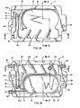
- FIGS. 1A and 1B show respectively a side elevation view of a front section and back section of a humidifier housing made in accordance with the present invention;
- FIG. 2 is a top view of the humidifier of composite FIG. 1; and
- FIG. 3 is an end view of the humidifier of composite FIG. 1.
- Referring now to the Drawings:
- The present invention avoids the disadvantages and deficiencies of the prior known devices by provision of a humidifier which has a minimum gas volume and is, thus, compact in size, and is capable of use with high frequency pulmonary assistance systems, the function of which is observable during operation. As shown in the drawings, a housing 11 includes a
front section 12 joined to aback section 13 by a suitable bond (FIGS. lA and lB show the sections laid open similar to a book with the section in FIG. lA being upside down and section in FIG. 1B being right side up.). The housing has the general shape of a rectangular prism and is formed of a suitable thermoplastic material which is transparent. Anair passage 14 is formed in the interior of the housing and is provided with a venturi section which includes an upstreamconvergent segment 15, anarrow throat 16 and a downstreamdivergent segment 17. A source of air under pressure is connected topassage 14 through anair inlet connector 18 in the upstream end of the housing. Due to the venturi effect of air passing through theconvergent segment 15, the velocity of air passing through thethroat 16 is increased, while the pressure of the air in the throat is correspondingly decreased. Conversely, in thedivergent section 17 the velocity of the air flow is reduced and the pressure correspondingly increased. - A
reservoir 19 is formed centrally in the housing and is supplied with water through aconnection 20 andchannel 20a in the upstream end of the housing. The upper portion of the reservoir is open to a portion of theair passage 14 so that the surface of the water is exposed to the pressure of the air therewithin. The pressure differential between the surface of the water in the reservoir and thethroat 16, combined with the aspirating effect of the air flow past the end of achannel 21, causes water to flow from the reservoir, through thechannel 21, into the throat. The position of the venturi section below the water level in the reservoir facilitates water pick up in a pulsing mode. The water discharged fromchannel 21 into the rapidly moving air flow in the throat is entrained in the flow and largely vaporized. - The
divergent segment 17 discharges into an enlargedscrubbing area 22 which extends over the length of the reservoir along its upper edge. A series ofvanes area 22. As the air flows through the scrubbing area, it strikes thevanes outlet 25 at the downstream end of the housing. - The
air passage 14 through the housing is configured such that the venturi section is located below the water level in the reservoir and the discharge from thedivergent segment 17 is vectored away form the reservoir. The location of the venturi ensures that water will always be present at thethroat 16 for entrainment in either a continuous or pulsing mode of operation. Vectoring the discharge from the divergent segment against the housing (vanes) rather than against the reservoir prevents formation of waves on the surface of the water in the reservoir which would cause entrainment of water droplets within the scrubbing area and consequent spitting at theoutlet 25. - A lateral wall of the
reservoir 19 on theback section 13 is formed by aflat cup 26 made of heat conductive material, such as aluminum, copper, etc., which is retained in sealing relation within anopening 27 in the section by means on an O-ring 28. The water within the reservoir is heated by application of heat to thecup 26. - The water level in the
reservoir 19 is sensed by a sensor which includes electricallyconductive pins pins pins - A
temperature sensor 32 is installed in the scrubbing area close to theoutlet 25 to sense the temperature of the air flow so that the heater can be regulated to maintain the water at the desired temperature with different rates of air flow. The sensor could be a conventional thermocouple temperature sensing device. - The front and back sections of the housing can be molded of clear plastic in an injection molding machine. The grooves and recesses in the facing surfaces of the front and back sections match with one another to define the various openings, passages, etc. when the sections are joined. The
metal cup 26 can be stamped from sheet material and pushed into place in the back section before the two sections are joined. The manufacture and assembly is simple and inexpensive, so that the humidifier can be discarded after use instead of being disassembled and sterilized. - The humidifier apparatus can be mounted on a control box with the aid of two guide pins received in
openings cup 26 on the back of the housing presses against a spring-loaded heater plate for good thermal contact. When the latches are released, the used humidifier can be removed from the pins. A new one is installed by placing the housing on the pins and pressing down until the latches snap in place. - The present humidifier can operate continuously or intermittently, as desired, can produce humid air in small quantities, and removes the entrained water droplets so that the moisture is delivered only in the form of water vapor. The transparent housing permits the function of the humidifier to be visually checked during the operation to detect any problems which might occur.
- While the invention has been described with reference to specifically illustrated preferred embodiments, it should be realized that various changes may be made without departing from the disclosed inventive subject matter particularly pointed out and claimed herebelow.
Claims (10)
Priority Applications (1)
| Application Number | Priority Date | Filing Date | Title |
|---|---|---|---|
| AT84113073T ATE44470T1 (en) | 1983-11-08 | 1984-10-30 | HUMIDIFIER, ESPECIALLY FOR RESPIRATORY ASSISTANCE SYSTEMS. |
Applications Claiming Priority (2)
| Application Number | Priority Date | Filing Date | Title |
|---|---|---|---|
| US54978983A | 1983-11-08 | 1983-11-08 | |
| US549789 | 1983-11-08 |
Publications (3)
| Publication Number | Publication Date |
|---|---|
| EP0141399A2 true EP0141399A2 (en) | 1985-05-15 |
| EP0141399A3 EP0141399A3 (en) | 1986-06-11 |
| EP0141399B1 EP0141399B1 (en) | 1989-07-12 |
Family
ID=24194392
Family Applications (1)
| Application Number | Title | Priority Date | Filing Date |
|---|---|---|---|
| EP84113073A Expired EP0141399B1 (en) | 1983-11-08 | 1984-10-30 | Humidifier, particularly for pulmonary assistance systems |
Country Status (7)
| Country | Link |
|---|---|
| US (1) | US4588425A (en) |
| EP (1) | EP0141399B1 (en) |
| JP (1) | JPS60122571A (en) |
| AT (1) | ATE44470T1 (en) |
| AU (1) | AU573762B2 (en) |
| CA (1) | CA1242640A (en) |
| DE (1) | DE3478900D1 (en) |
Cited By (1)
| Publication number | Priority date | Publication date | Assignee | Title |
|---|---|---|---|---|
| FR2618686A1 (en) * | 1987-07-31 | 1989-02-03 | Jean Louis Brunet | Apparatus for medical use intended for emitting a flow of air loaded with water vapour |
Families Citing this family (41)
| Publication number | Priority date | Publication date | Assignee | Title |
|---|---|---|---|---|
| US5490957A (en) * | 1994-09-28 | 1996-02-13 | Lasko; William E. | Portable humidifier |
| US5520854A (en) * | 1995-01-25 | 1996-05-28 | Ellis & Watts, Division Of Dynamics Corporation Of America | Apparatus and method for preventing the accumulation of bacteria in a humidifier |
| US5564415A (en) * | 1995-06-07 | 1996-10-15 | Lifecare International, Inc. | Humidifier for a ventilator |
| ATE342084T1 (en) | 1999-08-05 | 2006-11-15 | Map Medizin Technologie Gmbh | DEVICE FOR SUPPLYING A BREATHING GAS AND HUMIDIFIER DEVICE |
| EP3254722A3 (en) | 2001-02-16 | 2018-05-02 | ResMed Ltd. | Humidifier with structure to prevent backflow of liquid through the humidifier inlet |
| US20030051728A1 (en) | 2001-06-05 | 2003-03-20 | Lloyd Peter M. | Method and device for delivering a physiologically active compound |
| US7090830B2 (en) | 2001-05-24 | 2006-08-15 | Alexza Pharmaceuticals, Inc. | Drug condensation aerosols and kits |
| US7585493B2 (en) | 2001-05-24 | 2009-09-08 | Alexza Pharmaceuticals, Inc. | Thin-film drug delivery article and method of use |
| US7645442B2 (en) | 2001-05-24 | 2010-01-12 | Alexza Pharmaceuticals, Inc. | Rapid-heating drug delivery article and method of use |
| US7458374B2 (en) | 2002-05-13 | 2008-12-02 | Alexza Pharmaceuticals, Inc. | Method and apparatus for vaporizing a compound |
| US20070122353A1 (en) * | 2001-05-24 | 2007-05-31 | Hale Ron L | Drug condensation aerosols and kits |
| JP2003319996A (en) * | 2002-03-01 | 2003-11-11 | Sera Corp:Kk | Mist generating device |
| US20040105818A1 (en) | 2002-11-26 | 2004-06-03 | Alexza Molecular Delivery Corporation | Diuretic aerosols and methods of making and using them |
| US7913688B2 (en) | 2002-11-27 | 2011-03-29 | Alexza Pharmaceuticals, Inc. | Inhalation device for producing a drug aerosol |
| WO2004104490A1 (en) | 2003-05-21 | 2004-12-02 | Alexza Pharmaceuticals, Inc. | Self-contained heating unit and drug-supply unit employing same |
| NZ728764A (en) | 2003-06-20 | 2018-09-28 | ResMed Pty Ltd | Breathable gas apparatus with humidifier |
| AU2003903139A0 (en) | 2003-06-20 | 2003-07-03 | Resmed Limited | Breathable gas apparatus with humidifier |
| EP3050590B1 (en) * | 2003-08-20 | 2020-07-29 | Fisher & Paykel Healthcare Limited | Water chamber for humidifier |
| US7540286B2 (en) | 2004-06-03 | 2009-06-02 | Alexza Pharmaceuticals, Inc. | Multiple dose condensation aerosol devices and methods of forming condensation aerosols |
| CA2668702C (en) | 2006-11-06 | 2015-05-26 | Fisher & Paykel Healthcare Limited | Integrated humidifier chamber and lid |
| EP2121088B1 (en) | 2007-03-09 | 2016-07-13 | Alexza Pharmaceuticals, Inc. | Heating unit for use in a drug delivery device |
| NZ618492A (en) | 2008-06-05 | 2015-09-25 | Resmed Ltd | Treatment of respiratory conditions |
| US8517017B2 (en) | 2009-01-08 | 2013-08-27 | Hancock Medical, Inc. | Self-contained, intermittent positive airway pressure systems and methods for treating sleep apnea, snoring, and other respiratory disorders |
| US8931481B2 (en) | 2009-06-04 | 2015-01-13 | Redmed Limited | Flow generator chassis assembly with suspension seal |
| EP3738638A1 (en) | 2012-03-15 | 2020-11-18 | Fisher & Paykel Healthcare Limited | Respiratory gas humidification system |
| IN2014MN02333A (en) | 2012-04-27 | 2015-08-14 | Fisher & Paykel Healthcare Ltd | |
| US10314989B2 (en) | 2013-01-28 | 2019-06-11 | Hancock Medical, Inc. | Position control devices and methods for use with positive airway pressure systems |
| EP3043854B1 (en) | 2013-09-13 | 2019-11-06 | Fisher & Paykel Healthcare Limited | Humidification system |
| CA3166029A1 (en) | 2013-09-13 | 2015-03-19 | Fisher And Paykel Healthcare Limited | Circuit connector for a humidification system |
| CA3176263A1 (en) | 2013-12-20 | 2015-06-25 | Fisher & Paykel Healthcare Limited | Humidification system connections |
| US10449319B2 (en) | 2014-02-07 | 2019-10-22 | Fisher & Paykel Healthcare Limited | Respiratory humidification system |
| WO2015167347A1 (en) | 2014-05-02 | 2015-11-05 | Fisher & Paykel Healthcare Limited | Gas humidification arrangement |
| AU2015259944B2 (en) | 2014-05-13 | 2020-07-02 | Fisher & Paykel Healthcare Limited | Usability features for respiratory humidification system |
| EP3151894B1 (en) | 2014-06-03 | 2019-08-28 | Fisher & Paykel Healthcare Limited | Flow mixers for respiratory therapy systems |
| US10881829B2 (en) | 2014-08-18 | 2021-01-05 | Resmed Inc. | Portable pap device with humidification |
| EP3925654B1 (en) | 2014-11-17 | 2024-04-17 | Fisher & Paykel Healthcare Limited | Humidification of respiratory gases |
| USD776802S1 (en) | 2015-03-06 | 2017-01-17 | Hancock Medical, Inc. | Positive airway pressure system console |
| CN109310348B (en) | 2016-05-19 | 2022-01-25 | 汉考克医药公司 | Posture obstructive sleep apnea detection system |
| EP3551978B1 (en) | 2016-12-07 | 2022-01-26 | Fisher&Paykel Healthcare Limited | Sensing arrangements for medical devices |
| USD899598S1 (en) | 2018-09-04 | 2020-10-20 | 3B Medical, Inc. | CPAP device |
| CA3200085A1 (en) * | 2020-12-01 | 2022-06-09 | Bradley T. PIERCE | Thermogenic airway management device and methods |
Citations (6)
| Publication number | Priority date | Publication date | Assignee | Title |
|---|---|---|---|---|
| DE1930507A1 (en) * | 1969-06-16 | 1970-12-23 | Berthold & Sutter Abtlg Appbau | Producing an air mixture resembling a - 'sea-side climate' |
| CA870862A (en) * | 1969-06-13 | 1971-05-18 | N. Urbanowicz Nick | Injector |
| US4012473A (en) * | 1975-07-16 | 1977-03-15 | Arbrook, Inc. | Nebulizer-humidifier |
| US4098853A (en) * | 1974-03-25 | 1978-07-04 | Chemetron Corporation | Humidifier and automatic control system therefor |
| US4367182A (en) * | 1981-07-14 | 1983-01-04 | American Hospital Supply Corporation | Container with incorporated aerator |
| US5367182A (en) * | 1992-03-25 | 1994-11-22 | Nippondenso Co., Ltd. | Compound semiconductor device for reducing the influence of resistance anisotropy on operating characteristics thereof |
Family Cites Families (9)
| Publication number | Priority date | Publication date | Assignee | Title |
|---|---|---|---|---|
| US813217A (en) * | 1905-03-17 | 1906-02-20 | John H Kinealy | Air-purifying apparatus. |
| US3495440A (en) * | 1968-04-23 | 1970-02-17 | Us Army | Air sampler devices |
| US3884653A (en) * | 1973-07-27 | 1975-05-20 | Giuseppe Capulli | System for purification of gases |
| US3982095A (en) * | 1973-10-04 | 1976-09-21 | Searle Cardio-Pulmonary Systems Inc. | Respiratory humidifier |
| US4152379A (en) * | 1977-05-26 | 1979-05-01 | Airco, Inc. | Anesthesia humidifier |
| US4251236A (en) * | 1977-11-17 | 1981-02-17 | Ciba-Geigy Corporation | Process for purifying the off-gases from industrial furnaces, especially from waste incineration plants |
| GB1599900A (en) * | 1977-11-30 | 1981-10-07 | Rawicki B J | Dust extraction apparatus |
| US4267974A (en) * | 1979-07-25 | 1981-05-19 | C. R. Bard, Inc. | Nebulizer device |
| US4346048A (en) * | 1981-04-29 | 1982-08-24 | Gates James T | Humidifying system for mobile vehicles |
-
1984
- 1984-10-30 DE DE8484113073T patent/DE3478900D1/en not_active Expired
- 1984-10-30 EP EP84113073A patent/EP0141399B1/en not_active Expired
- 1984-10-30 AT AT84113073T patent/ATE44470T1/en not_active IP Right Cessation
- 1984-11-01 AU AU34877/84A patent/AU573762B2/en not_active Ceased
- 1984-11-07 CA CA000467193A patent/CA1242640A/en not_active Expired
- 1984-11-08 JP JP59234217A patent/JPS60122571A/en active Granted
-
1985
- 1985-03-26 US US06/716,199 patent/US4588425A/en not_active Expired - Lifetime
Patent Citations (6)
| Publication number | Priority date | Publication date | Assignee | Title |
|---|---|---|---|---|
| CA870862A (en) * | 1969-06-13 | 1971-05-18 | N. Urbanowicz Nick | Injector |
| DE1930507A1 (en) * | 1969-06-16 | 1970-12-23 | Berthold & Sutter Abtlg Appbau | Producing an air mixture resembling a - 'sea-side climate' |
| US4098853A (en) * | 1974-03-25 | 1978-07-04 | Chemetron Corporation | Humidifier and automatic control system therefor |
| US4012473A (en) * | 1975-07-16 | 1977-03-15 | Arbrook, Inc. | Nebulizer-humidifier |
| US4367182A (en) * | 1981-07-14 | 1983-01-04 | American Hospital Supply Corporation | Container with incorporated aerator |
| US5367182A (en) * | 1992-03-25 | 1994-11-22 | Nippondenso Co., Ltd. | Compound semiconductor device for reducing the influence of resistance anisotropy on operating characteristics thereof |
Cited By (1)
| Publication number | Priority date | Publication date | Assignee | Title |
|---|---|---|---|---|
| FR2618686A1 (en) * | 1987-07-31 | 1989-02-03 | Jean Louis Brunet | Apparatus for medical use intended for emitting a flow of air loaded with water vapour |
Also Published As
| Publication number | Publication date |
|---|---|
| EP0141399B1 (en) | 1989-07-12 |
| AU3487784A (en) | 1985-05-16 |
| DE3478900D1 (en) | 1989-08-17 |
| JPS60122571A (en) | 1985-07-01 |
| EP0141399A3 (en) | 1986-06-11 |
| JPH0422590B2 (en) | 1992-04-17 |
| AU573762B2 (en) | 1988-06-23 |
| CA1242640A (en) | 1988-10-04 |
| US4588425A (en) | 1986-05-13 |
| ATE44470T1 (en) | 1989-07-15 |
Similar Documents
| Publication | Publication Date | Title |
|---|---|---|
| US4588425A (en) | Humidifier | |
| US9961940B2 (en) | Vaporizing assembly and vapor generating device | |
| JP7054676B2 (en) | Aerosol generation system with pump | |
| US5063921A (en) | Nebulizer heater | |
| US5259370A (en) | Nebulizer heater | |
| GB2132508A (en) | Nebulizer with capillary feed | |
| EP0084633A3 (en) | Method for cleaning a web from particles and apparatus therefor | |
| SI1716796T1 (en) | Steam frothing device with froth flow regulation system | |
| GB1569043A (en) | Humidifier for a respiration gas | |
| EA200100532A1 (en) | SYSTEM FOR OBTAINING INHALED AEROSOL | |
| JPH02193678A (en) | Nebulizing device | |
| US5396884A (en) | High flow rate humidifier with baffle plates | |
| CN112263020A (en) | Electronic atomization device and battery device for same | |
| CN112493552A (en) | Double-air-passage device for preventing hole blockage and aerosol generating device | |
| DE3365564D1 (en) | Apparatus for cooling, drying and cleaning elongate material | |
| ATE34666T1 (en) | DEVICE FOR GENERATION OF WARM AIR FOR INHALATION. | |
| JP7208394B2 (en) | Heater assembly and flavor sucker | |
| KR102658269B1 (en) | Aerosol generator using incoming air heating | |
| LAWSON | Venturi design parameters for air injection into a foam fractionation system[Ph. D. Thesis] | |
| FR2341841A1 (en) | Drop-by-drop flowmeter for administering fluid to patient - has inlet tube with level gauge over apertured disc surrounded by drip collection chamber | |
| SU1642199A1 (en) | Nozzle for air sprinkling | |
| JPS561264A (en) | Soldering device | |
| KR20230131331A (en) | Aerosol generator using incoming air heating | |
| EP4287880A1 (en) | An aerosol-generating device comprising a heater | |
| RU2024105283A (en) | AEROSOL GENERATING SYSTEM MOUTHIP WITH CONDENSATION CONTROL |
Legal Events
| Date | Code | Title | Description |
|---|---|---|---|
| PUAI | Public reference made under article 153(3) epc to a published international application that has entered the european phase |
Free format text: ORIGINAL CODE: 0009012 |
|
| AK | Designated contracting states |
Designated state(s): AT BE CH DE FR GB IT LI NL SE |
|
| PUAL | Search report despatched |
Free format text: ORIGINAL CODE: 0009013 |
|
| AK | Designated contracting states |
Kind code of ref document: A3 Designated state(s): AT BE CH DE FR GB IT LI NL SE |
|
| 17P | Request for examination filed |
Effective date: 19861203 |
|
| 17Q | First examination report despatched |
Effective date: 19880203 |
|
| GRAA | (expected) grant |
Free format text: ORIGINAL CODE: 0009210 |
|
| AK | Designated contracting states |
Kind code of ref document: B1 Designated state(s): AT BE CH DE FR GB IT LI NL SE |
|
| REF | Corresponds to: |
Ref document number: 44470 Country of ref document: AT Date of ref document: 19890715 Kind code of ref document: T |
|
| ITF | It: translation for a ep patent filed |
Owner name: ING. A. GIAMBROCONO & C. S.R.L. |
|
| REF | Corresponds to: |
Ref document number: 3478900 Country of ref document: DE Date of ref document: 19890817 |
|
| ET | Fr: translation filed | ||
| PG25 | Lapsed in a contracting state [announced via postgrant information from national office to epo] |
Ref country code: AT Effective date: 19891030 |
|
| PG25 | Lapsed in a contracting state [announced via postgrant information from national office to epo] |
Ref country code: SE Effective date: 19891031 Ref country code: LI Effective date: 19891031 Ref country code: CH Effective date: 19891031 Ref country code: BE Effective date: 19891031 |
|
| BERE | Be: lapsed |
Owner name: BUNNELL LIFE SYSTEMS INC. Effective date: 19891031 |
|
| PG25 | Lapsed in a contracting state [announced via postgrant information from national office to epo] |
Ref country code: NL Effective date: 19900501 |
|
| PLBE | No opposition filed within time limit |
Free format text: ORIGINAL CODE: 0009261 |
|
| STAA | Information on the status of an ep patent application or granted ep patent |
Free format text: STATUS: NO OPPOSITION FILED WITHIN TIME LIMIT |
|
| NLV4 | Nl: lapsed or anulled due to non-payment of the annual fee | ||
| REG | Reference to a national code |
Ref country code: CH Ref legal event code: PL |
|
| 26N | No opposition filed | ||
| ITTA | It: last paid annual fee | ||
| PGFP | Annual fee paid to national office [announced via postgrant information from national office to epo] |
Ref country code: GB Payment date: 19931022 Year of fee payment: 10 |
|
| PGFP | Annual fee paid to national office [announced via postgrant information from national office to epo] |
Ref country code: FR Payment date: 19931028 Year of fee payment: 10 |
|
| PGFP | Annual fee paid to national office [announced via postgrant information from national office to epo] |
Ref country code: DE Payment date: 19931130 Year of fee payment: 10 |
|
| PG25 | Lapsed in a contracting state [announced via postgrant information from national office to epo] |
Ref country code: GB Effective date: 19941030 |
|
| EUG | Se: european patent has lapsed |
Ref document number: 84113073.5 Effective date: 19900706 |
|
| GBPC | Gb: european patent ceased through non-payment of renewal fee |
Effective date: 19941030 |
|
| PG25 | Lapsed in a contracting state [announced via postgrant information from national office to epo] |
Ref country code: FR Effective date: 19950630 |
|
| PG25 | Lapsed in a contracting state [announced via postgrant information from national office to epo] |
Ref country code: DE Effective date: 19950701 |
|
| REG | Reference to a national code |
Ref country code: FR Ref legal event code: ST |