EP0141375A2 - Wire accumulator - Google Patents
Wire accumulator Download PDFInfo
- Publication number
- EP0141375A2 EP0141375A2 EP84112817A EP84112817A EP0141375A2 EP 0141375 A2 EP0141375 A2 EP 0141375A2 EP 84112817 A EP84112817 A EP 84112817A EP 84112817 A EP84112817 A EP 84112817A EP 0141375 A2 EP0141375 A2 EP 0141375A2
- Authority
- EP
- European Patent Office
- Prior art keywords
- take
- speed
- guide rollers
- optical fiber
- accumulator
- Prior art date
- Legal status (The legal status is an assumption and is not a legal conclusion. Google has not performed a legal analysis and makes no representation as to the accuracy of the status listed.)
- Granted
Links
Images

Classifications
-
- B—PERFORMING OPERATIONS; TRANSPORTING
- B65—CONVEYING; PACKING; STORING; HANDLING THIN OR FILAMENTARY MATERIAL
- B65H—HANDLING THIN OR FILAMENTARY MATERIAL, e.g. SHEETS, WEBS, CABLES
- B65H51/00—Forwarding filamentary material
- B65H51/20—Devices for temporarily storing filamentary material during forwarding, e.g. for buffer storage
- B65H51/26—Rollers or bars mounted askew to facilitate movement of filamentary material along them, e.g. pairs of canted rollers
-
- B—PERFORMING OPERATIONS; TRANSPORTING
- B65—CONVEYING; PACKING; STORING; HANDLING THIN OR FILAMENTARY MATERIAL
- B65H—HANDLING THIN OR FILAMENTARY MATERIAL, e.g. SHEETS, WEBS, CABLES
- B65H51/00—Forwarding filamentary material
- B65H51/20—Devices for temporarily storing filamentary material during forwarding, e.g. for buffer storage
Definitions
- the invention pertains in general to the art of wire or filament manufacture.
- the invention is a wire accumulator for use in a wire or filament manufacturing facility, particularly for a wire or filament having low tensile strength and which is therefore easily broken, such as, for example, an optical fiber.
- a typical manufacturing facility may include a machine for drawing an optical fiber, a first take-up device downstream of the drawing machine, a tensile- strength testing machine for testing the tensile strength of optical fiber during its travel, and a winding device for winding the optical fiber on a bobbin.
- Optical fiber is a relatively weak filament and is therefore easily broken in the tensile strength testing machine. It is, therefore, usual to provide an accumulator and a second take-up device between the first take-up device and the tensile strength testing machine to facilitate replacement of the optical fiber without stopping the drawing machine when the fiber has broken.
- Commonly assigned U.S. application has been filed with Serial No. 502,059 filed on June 7, 1983 to an accumulator, and a Japanese application for utility model registration under No. 40340/1983 has been filed directed to an improve-Rent thereon. The invention set forth in this application is a further improvement over those accumulators.
- FIGURES 1-4 there is shown a known accumulator.
- Optical fiber 1 is drawn into the accumulator at a constant speed from a drawing machine (not shown) by a first take-up device 2, past guide rollers 17 and to a second take-up device 9 via dancer rollers 11 which control the speed of optical fiber on the second take-up device.
- the fiber is subjected to a tensile strength test by a tensile testing machine 27, and wound by a winder (not shown) downstream of dancer rollers 28 which control the winding speed, as shown by arrows in FIGURE 1 (PRIOR ART).
- the accumulator includes two groups Y and Z of cylindrical accumulating guide rollers 3 which are rotatably supported on bearings 5 and shafts 6 and 6' secured at equal intervals in a circular array to side plates 7 and 8, and 7' and 8', respectively, as shown in FIGURES 1 and 2 (PRIOR ART).
- Each guide roller 3 is formed around its outer periphery with a plurality of grooves 4 which are equally spaced apart from one another at a pitch P.
- the grooves 4 on the guide rollers 3 or 3' are slightly displaced axially from one guide roller to another, as shown in FIGURE 2 (PRIOR ART).
- a shaft 14 extending through the center of the guide roller assembly Z is rotatably supported by bearings 12 on a stand 10.
- a variable speed motor 13 is provided at one end of the shaft 14 for driving it, and an arm 15 is secured to the other end of the shaft 14.
- a guide bar 16 is secured to the outer end of the arm 15.
- Moving blocks 18 and 18' are slidable transversely along the guide bar 16 as shown in FIGURE 3 (PRIOR ART).
- Guide rollers 17 and 17' for distributing optical fiber to the accumulating guide roller assemblies Y and Z are rotatably carried on the blocks 18 and 18', respectively.
- a screw shaft 21 is rotatably supported by bearings 20 on the support members 19 and 19' secured to the opposite ends of the guide bar 16 and the arm 15, and extends in parallel to the guide bar 16.
- the screw shaft 21 has threaded portions 22 and 23 on both sides of the arm 15, and they are fastened to the moving blocks 18 and 18' by nuts.
- Threaded portion 22 has a right-hand screw, and threaded portion 23 a left-hand screw.
- Each screw has a pitch which is equal to pitch P of the grooves 4 on the guide rollers 3.
- a timing belt pulley 24 is provided on screw shaft 21 and connected by a timing belt 26 to a timing belt pulley 25 provided on the side plate 7 of the guide roller assembly Y coaxially with the shaft 14, as shown in FIGURES 1 and 4 (PRIOR ART).
- the two timing belt pulleys have a rotation ratio of 1:1.
- optical fiber passes through the first take-up device 2, the distributing guide rollers 17 and 17', the second take-up device 9 and the tensile testing machine 27 without winding about rollers 3, and is wound on the winder (not shown), as shown by the- arrows in FIGURE 1 (PRIOR ART).
- the second take-up device gradually reduces its speed, and simultaneously, the variable speed motor 13 is driven to rotate the shaft 14 in the direction of an arrow R in FIGURE 1 (PRIOR ART).
- the rotation of the shaft 14 causes the rotation of the arm 15 and the distributing guide rollers 17 and 17' about the accumulating guide roller assemblies in the direction of an arrow Q in FIGURE 4 (PRIOR ART) thereby winding and accumulating optical fiber on the accumulating guide roller assemblies.
- the screw shaft is caused to rotate relative to the blocks 18 and 18' in the direction of an arrow T in FIGURE 1 by the same angular distance as that of rotation of the shaft 14.
- screws 22 and 23 cause the right-hand movement of the distributing guide roller 17 and the left-hand movement of the guide roller 17'.
- the rotation of the shaft 14 results in the orderly distribution, winding and accumulation of optical fiber in the grooves 4 of the accumulating guide roller assemblies.
- the second take-up device which has gradually reduced its speed, reaches stability at a constant speed.
- Optical fiber is withdrawn at a low speed and guided manually to the winder through the tension testing machine.
- the rotating speed of the variable speed motor 13 is adjusted so that the difference in take-up speed between the first and second take-up devices may effect accumulation of optical fiber. If the apparatus is brought back to its normal operating condition, the second take-up device is rotated at a higher speed than the first take-up device and motor 13 is rotated in the opposite direction, so that optical fiber may be released from the accumulator.
- the speed of optical fiber leaving the second take-up device is, therefore, the sum of the take-up speed of the first take-up device and the speed of the optical fiber released from the accumulator.
- the speed of the second take-up device is lowered to coincide with that of the first take-up device, i.e., of the drawing machine.
- the speed of the second take-up device is lowered to coincide with that of the first take-up device, i.e., of the drawing machine.
- the conventional apparatus as hereinabove described has, however, a number of disadvantages.
- the bearings 5 are subjected to a high degree of frictional resistance, and as the guide rollers for accumulating optical fiber are caused by the optical fiber to rotate at a speed coinciding with the traveling speed of the optical fiber to be accumulated, the guide rollers impose on the optical fiber an increased tension which may result in breakage, or a worsening of its properties even if it may not be broken.
- the inertia of the guide roller causes a change in the tension of the optical fiber whenever the rotating speed of the guide rollers is varied.
- Japanese Utility Model Application No. 40340/1983 proposes an improvement which is shown in FIGURE 5.
- the accumulating guide rollers are fixed to shafts 6 and 6'.
- the guide roller assembly Y is rotated by timing belts 35 and 37 via timing belt pulleys in such a way that the peripheral speed of the grooves on the rollers may coincide with the speed of optical fiber on the first take-up device 2.
- the shafts 6' for the guide roller assembly Z are driven as a result of operation by a differential gear assembly 42 on the speed of optical fiber on the first take-up device and the speed of accumulation by the rotation of the arm 14.
- the peripheral speeds of the guide roller assemblies Y and Z are always maintained equal to the speed of optical fiber traveling past them.
- the FIGURE 5 arrangement uses a differential gear unit, its backlash creates an instantaneous speed change in the guide roller assembly Z and it causes a change in the tension of a wire or filament on the distributing guide rollers.
- the accumulator comprises a plurality of guide rollers equally spaced apart from one another in a circular array, the wire or filament which is accumulated has a polygonal shape, and therefore, the wire or filament on the distributing guide rollers is subjected to the same number of pulsing speed changes as that of the sides of the polygon during each rotation about the accumulator when it is accumulated or released. This causes a change in the tension of the wire or filament on the distributing guide rollers.
- the conventional system employs the electrical control by the variable speed motor 13 of the speed of the optical fiber to be accumulated or released, and also requires the electrical control of the take-up speed on the second take-up device 9. An error is likely to develop between these two kinds of control. The correction-of this error requires a complicated system, as it is necessary to correct the speed of the second take-up device 9 by the speed control dancer rollers 11.
- the accumulating guide roller assembly Z is mechanically connected to the second take-up device so that the surface velocity of the assembly Z may coincide with the take-up speed of the second take-up device.
- Tension and speed control means such as dancer rollers, are provided between the distributing guide rollers 17 and 17' to maintain optical fiber at a constant tension and detect the length (or amount) of optical fiber therebetween.
- the tension and speed control means transmits a signal to the variable speed motor to correct the speed of-optical fiber to be accumulated or released, or to a driving system for the second take-up device to correct its speed.
- the accumulator of this invention differs from the conventional apparatus in that the peripheral speeds of the accumulating guide roller assemblies Y and Z are always caused by the mutually independent mechanical connections to coincide with the take-up speeds of the first and second take-up devices, respectively, when optical fiber is wound for accumulation on the accumulator by the distributing guide rollers rotating coaxially with the accumulator. Therefore, the speed of the optical fiber being accumulated is always equal to the peripheral speed of the accumulating guide rollers, and there is no instantaneous tension change that might otherwise result from the backlash of the interconnecting gears.
- the optical fiber is accumulated at a constant tension, since the take-up speed of the second take-up device or the speed of the optical fiber accumulation is finely controlled in accordance with a control signal transmitted by the tension and speed control device provided in the passage for optical fiber between the distributing guide rollers.
- the accumulating capacity of the tension and speed control device absorbs any tension change caused by the polygonal arrangement of the accumulating guide rollers.
- the accumulator of this invention is very effective for use with a drawing machine for - producing a wire or filament having a low tensile strength and which may be easily broken, such as optical fiber.
- FIGURE 6 is a front elevational view of a preferred embodiment of this invention. Like reference numerals are used to designate parts that are like or corresponding to those of the other FIGURES.
- Timing belt pulleys 34 of the same size are provided on one end of each shaft 6 in the guide roller assembly Y, and connected by a single timing belt 35 so that all of the guide rollers may be able to rotate at the same speed in the same direction.
- a timing belt pulley 36 is provided on one of the shafts 6, and driven by a driving timing belt 37.
- the timing belt 37 is driven from the shaft of a variable speed motor 39 which drives the first take-up device 2 through a speed changer 40.
- Timing belt pulleys 30 of the same size are provided on the opposite end of each shaft 6' in the guide roller assembly Z, and connected by a single timing belt 31 so that all of the guide rollers may be able to rotate at the same speed in the same - direction.
- a timing belt pulley 32 is provided on one of the shafts 6' and driven by a driving timing belt 33 which is connected to the shaft of a variable speed motor 44 which drives the second take-up device 9 through a speed changer having a constant speed change ratio i10.
- the timing belt pulley 32 is designed to provide the timing belts with a transmission ratio of i8 and i9 to enable the peripheral speed of the grooves on the guide rollers 3' to coincide with the take-up speed of the second take-up device 9.
- timing belt transmissions i8 and i9 are shown, it is, of course, possible to employ only a single transmission if it provides the same transmission ratio. It is also possible to use any connecting means other than the timing belts if it enables transmission at an accurate speed ratio.
- the arm 15 is secured to the end of the shaft 14 extending through the center of the guide roller assembly Z and driven by the variable speed motor 13.
- the distributing guide rollers 17 and 17' are transversely movably provided on the end of the arm 15 to accumulate the wire or filament on the accumulating guide rollers.
- Tension and speed control means 45 such as dancer rollers, are provided between the distributing guide rollers 17 and 17'.
- a signal representing the displacement of the dancer roller 6r like means is transmitted through the arm 15 and picked up through a slip ring 46 provided on the shaft 14.
- the optical fiber leaving the drawing machine passes through the wheel of the first take-up device 2 which is driven by the motor 39 via the speed changer 40, the distributing guide roller 17, the tension and speed control device 45, the distributing guide roller 17' and the wheel of the second take-up device 9.
- the speed of the second take-up device 9 is changed, and the shaft 14 and the arm 15 are driven by the motor 13 to drive the distributing guide rollers 17 and 17' so that optical fiber may be wound on the accumulating guide roller assemblies Y and Z.
- the variable speed motors 13 and 44 are controlled to ensure that the winding or unwinding speed V 3 be always equal to the take-up speed V 1 of the first take-up device 2 less the take-up speed V 5 of the second take-up device 9.
- the peripheral speed V 2 of the guide roller assembly Y is always equal to the take-up speed V 1 of the first take-up device 2, as they are mechanically connected to each other, and the peripheral speed V 4 of the guide roller assembly Z is always equal to the take-up speed V 5 of the second take-up device 9, as they are mechanically connected to each other.
- the speed of the optical fiber accumulated on the guide rollers is always equal to the peripheral speed of the bottom of the grooves on the guide rollers.
- a difference is likely to arise between the take-up speed V 5 of the second take-up device 9 and the speed V 5 of accumulation by the variable speed motor 44, as they are controlled from an external source.
- the difference is, however, detected by way of the displacement of the dancer roller or like control means 45 between the distributing guide rollers 17 and 17', and a signal is picked up through the slip ring 46 on the shaft 14 to correct the external control of the motors 13 and 44.
- This enables the optical fiber to be accumulated without loosening or being unduly stretched. It is, of course, effective to make such correction for either of the motors 13 and 44.
- the tension and speed control device 45 maintains the - optical fiber at a constant tension and as it has some accumulating capacity, it absorbs any slight changes in the speed of optical fiber that is due to the polygonal arrangement of the accumulating guide rollers.
- the device 45 is preferably of the construction not creating any tension change by centrifugal force as it is positioned for rotation about the accumulating guide rollers.
Landscapes
- Tension Adjustment In Filamentary Materials (AREA)
- Surgical Instruments (AREA)
- Mechanical Treatment Of Semiconductor (AREA)
- Harvester Elements (AREA)
- Forwarding And Storing Of Filamentary Material (AREA)
- Manufacture, Treatment Of Glass Fibers (AREA)
- Investigating Or Analyzing Materials By The Use Of Ultrasonic Waves (AREA)
- Ultra Sonic Daignosis Equipment (AREA)
- Measurement Of Velocity Or Position Using Acoustic Or Ultrasonic Waves (AREA)
Abstract
Description
- This invention pertains in general to the art of wire or filament manufacture. Specifically, the invention is a wire accumulator for use in a wire or filament manufacturing facility, particularly for a wire or filament having low tensile strength and which is therefore easily broken, such as, for example, an optical fiber.
- A typical manufacturing facility may include a machine for drawing an optical fiber, a first take-up device downstream of the drawing machine, a tensile- strength testing machine for testing the tensile strength of optical fiber during its travel, and a winding device for winding the optical fiber on a bobbin. Optical fiber is a relatively weak filament and is therefore easily broken in the tensile strength testing machine. It is, therefore, usual to provide an accumulator and a second take-up device between the first take-up device and the tensile strength testing machine to facilitate replacement of the optical fiber without stopping the drawing machine when the fiber has broken. Commonly assigned U.S. application has been filed with Serial No. 502,059 filed on June 7, 1983 to an accumulator, and a Japanese application for utility model registration under No. 40340/1983 has been filed directed to an improve-Rent thereon. The invention set forth in this application is a further improvement over those accumulators.
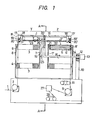
- Referring now to FIGURES 1-4 (PRIOR ART), there is shown a known accumulator. Optical fiber 1 is drawn into the accumulator at a constant speed from a drawing machine (not shown) by a first take-up device 2,
past guide rollers 17 and to a second take-updevice 9 viadancer rollers 11 which control the speed of optical fiber on the second take-up device. From - second take-updevice 9, the fiber is subjected to a tensile strength test by atensile testing machine 27, and wound by a winder (not shown) downstream ofdancer rollers 28 which control the winding speed, as shown by arrows in FIGURE 1 (PRIOR ART). The accumulator includes two groups Y and Z of cylindrical accumulatingguide rollers 3 which are rotatably supported onbearings 5 andshafts 6 and 6' secured at equal intervals in a circular array toside plates guide roller 3 is formed around its outer periphery with a plurality ofgrooves 4 which are equally spaced apart from one another at a pitch P. Thegrooves 4 on theguide rollers 3 or 3' are slightly displaced axially from one guide roller to another, as shown in FIGURE 2 (PRIOR ART). Ashaft 14 extending through the center of the guide roller assembly Z is rotatably supported bybearings 12 on astand 10. Avariable speed motor 13 is provided at one end of theshaft 14 for driving it, and anarm 15 is secured to the other end of theshaft 14. Aguide bar 16 is secured to the outer end of thearm 15. Movingblocks 18 and 18' are slidable transversely along theguide bar 16 as shown in FIGURE 3 (PRIOR ART).Guide rollers 17 and 17' for distributing optical fiber to the accumulating guide roller assemblies Y and Z are rotatably carried on theblocks 18 and 18', respectively. Ascrew shaft 21 is rotatably supported bybearings 20 on thesupport members 19 and 19' secured to the opposite ends of theguide bar 16 and thearm 15, and extends in parallel to theguide bar 16. Thescrew shaft 21 has threadedportions arm 15, and they are fastened to the movingblocks 18 and 18' by nuts. Threadedportion 22 has a right-hand screw, and threaded portion 23 a left-hand screw. Each screw has a pitch which is equal to pitch P of thegrooves 4 on theguide rollers 3. Thus, each rotation of thescrew shaft 21 causes the movement of the movingblocks 18 and 18' in opposite directions by a distance equal to the pitch of thegrooves 4. Atiming belt pulley 24 is provided onscrew shaft 21 and connected by atiming belt 26 to atiming belt pulley 25 provided on theside plate 7 of the guide roller assembly Y coaxially with theshaft 14, as shown in FIGURES 1 and 4 (PRIOR ART). The two timing belt pulleys have a rotation ratio of 1:1. - If the optical fiber drawing machine is in normal operation, optical fiber passes through the first take-up device 2, the distributing
guide rollers 17 and 17', the second take-updevice 9 and thetensile testing machine 27 without winding aboutrollers 3, and is wound on the winder (not shown), as shown by the- arrows in FIGURE 1 (PRIOR ART). - If optical fiber is broken in the
tensile testing machine 27, the second take-up device gradually reduces its speed, and simultaneously, thevariable speed motor 13 is driven to rotate theshaft 14 in the direction of an arrow R in FIGURE 1 (PRIOR ART). The rotation of theshaft 14 causes the rotation of thearm 15 and the distributingguide rollers 17 and 17' about the accumulating guide roller assemblies in the direction of an arrow Q in FIGURE 4 (PRIOR ART) thereby winding and accumulating optical fiber on the accumulating guide roller assemblies. As thetiming belt pulley 25 on theside plate 7 and thetiming belt pulley 24 on thescrew shaft 21 are connected to each other by thetiming belt 26, the screw shaft is caused to rotate relative to theblocks 18 and 18' in the direction of an arrow T in FIGURE 1 by the same angular distance as that of rotation of theshaft 14. As a result,screws guide roller 17 and the left-hand movement of the guide roller 17'. As the pitch of the screws is equal to that of the grooves on the accumulating guide rollers, the rotation of theshaft 14 results in the orderly distribution, winding and accumulation of optical fiber in thegrooves 4 of the accumulating guide roller assemblies. The second take-up device, which has gradually reduced its speed, reaches stability at a constant speed. Optical fiber is withdrawn at a low speed and guided manually to the winder through the tension testing machine. The rotating speed of thevariable speed motor 13 is adjusted so that the difference in take-up speed between the first and second take-up devices may effect accumulation of optical fiber. If the apparatus is brought back to its normal operating condition, the second take-up device is rotated at a higher speed than the first take-up device andmotor 13 is rotated in the opposite direction, so that optical fiber may be released from the accumulator. The speed of optical fiber leaving the second take-up device is, therefore, the sum of the take-up speed of the first take-up device and the speed of the optical fiber released from the accumulator. If all of the accumulated optical fiber has been released, the speed of the second take-up device is lowered to coincide with that of the first take-up device, i.e., of the drawing machine. Thus, any breakage of optical fiber.in the tensile testing machine can be rectified without lowering the speed of the drawing machine or stopping it. - The conventional apparatus as hereinabove described has, however, a number of disadvantages. As the
shafts 6 and 6' for the accumulatingguide rollers 3 and 3' are fixed, thebearings 5 are subjected to a high degree of frictional resistance, and as the guide rollers for accumulating optical fiber are caused by the optical fiber to rotate at a speed coinciding with the traveling speed of the optical fiber to be accumulated, the guide rollers impose on the optical fiber an increased tension which may result in breakage, or a worsening of its properties even if it may not be broken. Moreover, the inertia of the guide roller causes a change in the tension of the optical fiber whenever the rotating speed of the guide rollers is varied. - Japanese Utility Model Application No. 40340/1983 proposes an improvement which is shown in FIGURE 5. The accumulating guide rollers are fixed to
shafts 6 and 6'. The guide roller assembly Y is rotated bytiming belts differential gear assembly 42 on the speed of optical fiber on the first take-up device and the speed of accumulation by the rotation of thearm 14. Thus, the peripheral speeds of the guide roller assemblies Y and Z are always maintained equal to the speed of optical fiber traveling past them. - As the FIGURE 5 arrangement uses a differential gear unit, its backlash creates an instantaneous speed change in the guide roller assembly Z and it causes a change in the tension of a wire or filament on the distributing guide rollers. As the accumulator comprises a plurality of guide rollers equally spaced apart from one another in a circular array, the wire or filament which is accumulated has a polygonal shape, and therefore, the wire or filament on the distributing guide rollers is subjected to the same number of pulsing speed changes as that of the sides of the polygon during each rotation about the accumulator when it is accumulated or released. This causes a change in the tension of the wire or filament on the distributing guide rollers.
- It is necessary to prevent such tension changes from occurring when the manufacturing process requires the maintenance of a low tension which does not make any appreciable change. the conventional system employs the electrical control by the
variable speed motor 13 of the speed of the optical fiber to be accumulated or released, and also requires the electrical control of the take-up speed on the second take-updevice 9. An error is likely to develop between these two kinds of control. The correction-of this error requires a complicated system, as it is necessary to correct the speed of the second take-updevice 9 by the speedcontrol dancer rollers 11. - The present invention solves this tension change problem. According to this invention, the accumulating guide roller assembly Z is mechanically connected to the second take-up device so that the surface velocity of the assembly Z may coincide with the take-up speed of the second take-up device. Tension and speed control means, such as dancer rollers, are provided between the distributing
guide rollers 17 and 17' to maintain optical fiber at a constant tension and detect the length (or amount) of optical fiber therebetween. The tension and speed control means transmits a signal to the variable speed motor to correct the speed of-optical fiber to be accumulated or released, or to a driving system for the second take-up device to correct its speed. These arrangements make it possible to prevent any tension change that might otherwise arise from the inertia and polygonal arrangement of the accumulating guide rollers, and thereby enable optical fiber to be accumulated or released properly. - The accumulator of this invention differs from the conventional apparatus in that the peripheral speeds of the accumulating guide roller assemblies Y and Z are always caused by the mutually independent mechanical connections to coincide with the take-up speeds of the first and second take-up devices, respectively, when optical fiber is wound for accumulation on the accumulator by the distributing guide rollers rotating coaxially with the accumulator. Therefore, the speed of the optical fiber being accumulated is always equal to the peripheral speed of the accumulating guide rollers, and there is no instantaneous tension change that might otherwise result from the backlash of the interconnecting gears. The optical fiber is accumulated at a constant tension, since the take-up speed of the second take-up device or the speed of the optical fiber accumulation is finely controlled in accordance with a control signal transmitted by the tension and speed control device provided in the passage for optical fiber between the distributing guide rollers. The accumulating capacity of the tension and speed control device absorbs any tension change caused by the polygonal arrangement of the accumulating guide rollers. Thus, the accumulator of this invention is very effective for use with a drawing machine for - producing a wire or filament having a low tensile strength and which may be easily broken, such as optical fiber.
- The invention will now be described in detail with reference to the drawings.
-
- FIGURE 1 (PRIOR ART) is a front elevational view of a conventional accumulator;
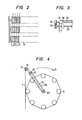
- FIGURE 2 (PRIOR ART) is a front elevational view showing the arrangement of accumulating guide rollers;
- FIGURE 3 (PRIOR ART) is a detailed view of a portion designated at B in FIGURE 1;
- FIGURE 4 (PRIOR ART) is a sectional view taken along the line A-A of FIGURE 1;
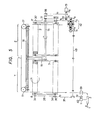
- FIGURE 5 is a diagram showing a driving system for another accumulator known in the art; and
- FIGURE 6 is a diagram showing a driving system for an accumulator embodying this invention.
- FIGURE 6 is a front elevational view of a preferred embodiment of this invention. Like reference numerals are used to designate parts that are like or corresponding to those of the other FIGURES.
- Accumulating
guide rollers 3 and 3' are fixed to theshafts 6 and 6' supported rotatably bybearings 29 and 29' on theside plates shaft 6 in the guide roller assembly Y, and connected by asingle timing belt 35 so that all of the guide rollers may be able to rotate at the same speed in the same direction. Atiming belt pulley 36 is provided on one of theshafts 6, and driven by a drivingtiming belt 37. Thetiming belt 37 is driven from the shaft of avariable speed motor 39 which drives the first take-up device 2 through aspeed changer 40. - Timing belt pulleys 30 of the same size are provided on the opposite end of each shaft 6' in the guide roller assembly Z, and connected by a
single timing belt 31 so that all of the guide rollers may be able to rotate at the same speed in the same - direction. Atiming belt pulley 32 is provided on one of the shafts 6' and driven by a drivingtiming belt 33 which is connected to the shaft of avariable speed motor 44 which drives the second take-updevice 9 through a speed changer having a constant speed change ratio i10. Thetiming belt pulley 32 is designed to provide the timing belts with a transmission ratio of i8 and i9 to enable the peripheral speed of the grooves on the guide rollers 3' to coincide with the take-up speed of the second take-updevice 9. Although two timing belt transmissions i8 and i9 are shown, it is, of course, possible to employ only a single transmission if it provides the same transmission ratio. It is also possible to use any connecting means other than the timing belts if it enables transmission at an accurate speed ratio. - The
arm 15 is secured to the end of theshaft 14 extending through the center of the guide roller assembly Z and driven by thevariable speed motor 13. The distributingguide rollers 17 and 17' are transversely movably provided on the end of thearm 15 to accumulate the wire or filament on the accumulating guide rollers. Tension and speed control means 45, such as dancer rollers, are provided between the distributingguide rollers 17 and 17'. A signal representing the displacement of the dancer roller 6r like means is transmitted through thearm 15 and picked up through aslip ring 46 provided on theshaft 14. - The operation of the apparatus will be described with reference to FIGURE 6. When the apparatus is in its normal operating condition, the optical fiber leaving the drawing machine passes through the wheel of the first take-up device 2 which is driven by the
motor 39 via thespeed changer 40, the distributingguide roller 17, the tension andspeed control device 45, the distributing guide roller 17' and the wheel of the second take-updevice 9. - If it has become necessary to accumulate optical.fiber, the speed of the second take-up
device 9 is changed, and theshaft 14 and thearm 15 are driven by themotor 13 to drive the distributingguide rollers 17 and 17' so that optical fiber may be wound on the accumulating guide roller assemblies Y and Z. Thevariable speed motors device 9. - According to the arrangement hereinabove described, the peripheral speed V2 of the guide roller assembly Y is always equal to the take-up speed V1 of the first take-up device 2, as they are mechanically connected to each other, and the peripheral speed V4 of the guide roller assembly Z is always equal to the take-up speed V5 of the second take-up
device 9, as they are mechanically connected to each other. It follows that the speed of the optical fiber accumulated on the guide rollers is always equal to the peripheral speed of the bottom of the grooves on the guide rollers. Thus, there is no sliding of optical fiber relative to the guide rollers. There is, therefore, no tension created by the friction between the optical fiber and the guide rollers. - A difference is likely to arise between the take-up speed V5 of the second take-up
device 9 and the speed V5 of accumulation by thevariable speed motor 44, as they are controlled from an external source. The difference is, however, detected by way of the displacement of the dancer roller or like control means 45 between the distributingguide rollers 17 and 17', and a signal is picked up through theslip ring 46 on theshaft 14 to correct the external control of themotors motors speed control device 45 maintains the - optical fiber at a constant tension and as it has some accumulating capacity, it absorbs any slight changes in the speed of optical fiber that is due to the polygonal arrangement of the accumulating guide rollers. Thedevice 45 is preferably of the construction not creating any tension change by centrifugal force as it is positioned for rotation about the accumulating guide rollers. - Other embodiments and modifications of the present invention will be apparent to those of ordinary skill in the art having the benefit of the teaching presented in the foregoing description and drawings. It is, therefore, to be understood that this invention is not to be unduly limited and such modification are intended to be included within the scope of the appended claims.
Claims (4)
Priority Applications (1)
| Application Number | Priority Date | Filing Date | Title |
|---|---|---|---|
| AT84112817T ATE39910T1 (en) | 1983-11-08 | 1984-10-24 | WIRE STORAGE DEVICE. |
Applications Claiming Priority (2)
| Application Number | Priority Date | Filing Date | Title |
|---|---|---|---|
| JP58210572A JPS60102370A (en) | 1983-11-08 | 1983-11-08 | Wire storage apparatus |
| JP210572/83 | 1983-11-08 |
Publications (3)
| Publication Number | Publication Date |
|---|---|
| EP0141375A2 true EP0141375A2 (en) | 1985-05-15 |
| EP0141375A3 EP0141375A3 (en) | 1986-12-03 |
| EP0141375B1 EP0141375B1 (en) | 1989-01-11 |
Family
ID=16591533
Family Applications (1)
| Application Number | Title | Priority Date | Filing Date |
|---|---|---|---|
| EP84112817A Expired EP0141375B1 (en) | 1983-11-08 | 1984-10-24 | Wire accumulator |
Country Status (10)
| Country | Link |
|---|---|
| US (1) | US4641794A (en) |
| EP (1) | EP0141375B1 (en) |
| JP (1) | JPS60102370A (en) |
| KR (1) | KR870001477B1 (en) |
| AT (1) | ATE39910T1 (en) |
| AU (1) | AU571602B2 (en) |
| CA (1) | CA1238620A (en) |
| DE (1) | DE3476059D1 (en) |
| DK (1) | DK162933C (en) |
| FI (1) | FI76999C (en) |
Families Citing this family (4)
| Publication number | Priority date | Publication date | Assignee | Title |
|---|---|---|---|---|
| JPS6455956U (en) * | 1987-09-30 | 1989-04-06 | ||
| US4749137A (en) * | 1987-10-26 | 1988-06-07 | Nokia Corporation | Strand accumulator with rotatable drum and rolls |
| IT1226188B (en) * | 1988-11-16 | 1990-12-21 | Casagrande Spa | ACCUMULATION PROCEDURE FOR FILIFORM PRODUCTS AND RELATED ACCUMULATION DRUM FOR FILIFORM PRODUCTS |
| US7485201B2 (en) * | 2001-12-21 | 2009-02-03 | Pirelli Pneumatici S.P.A. | Automatic plant and method for producing tires |
Citations (3)
| Publication number | Priority date | Publication date | Assignee | Title |
|---|---|---|---|---|
| FR2151558A5 (en) * | 1971-09-03 | 1973-04-20 | Defontenay Paul | |
| US3817067A (en) * | 1972-09-05 | 1974-06-18 | Minster Machine Co | Stock supply system |
| FR2211938A5 (en) * | 1972-12-26 | 1974-07-19 | Kobe Steel Ltd |
Family Cites Families (14)
| Publication number | Priority date | Publication date | Assignee | Title |
|---|---|---|---|---|
| US2165259A (en) * | 1936-03-23 | 1939-07-11 | Ind Rayon Corp | Thread store device |
| GB531265A (en) * | 1938-08-03 | 1941-01-01 | Comp Generale Electricite | Improvements in traversing devices for use on winding cables |
| US2755916A (en) * | 1954-05-13 | 1956-07-24 | Vaughn Machinery Co | Wire storage and regulating means |
| US3017130A (en) * | 1955-01-17 | 1962-01-16 | Kenneth K Knight | Accumulator device for a flexible element |
| DE1084798B (en) * | 1958-09-30 | 1960-07-07 | Siemens Ag | Device for the intermediate storage of continuously moving flexible strings on a storage drum, in particular electrical wires overmolded with plastic |
| US3078055A (en) * | 1960-04-06 | 1963-02-19 | Acrometal Products Inc | Filament accumulator |
| US3099412A (en) * | 1962-04-02 | 1963-07-30 | Western Electric Co | Strand control apparatus |
| US3241780A (en) * | 1963-08-05 | 1966-03-22 | Indiana Steel & Wire Company I | Wire tensioning filament feeding apparatus |
| CH564613A5 (en) * | 1971-06-19 | 1975-07-31 | Pavena Ag | |
| JPS513913A (en) * | 1974-07-04 | 1976-01-13 | Yanmar Agricult Equip | |
| JPS5249231A (en) * | 1975-10-17 | 1977-04-20 | Mitsui Mining & Smelting Co | Fillers |
| DE2847291C2 (en) * | 1978-10-31 | 1986-06-19 | Lucke-Apparate-Bau GmbH, 7947 Mengen | Device for the continuous depositing of a yarn or other threadlike material |
| JPS5917015B2 (en) * | 1978-12-27 | 1984-04-19 | 株式会社フジクラ | Accumulator |
| JPS58216206A (en) * | 1982-06-10 | 1983-12-15 | Nippon Telegr & Teleph Corp <Ntt> | Wire storing apparatus for wire drawing bench |
-
1983
- 1983-11-08 JP JP58210572A patent/JPS60102370A/en active Granted
-
1984
- 1984-10-24 DE DE8484112817T patent/DE3476059D1/en not_active Expired
- 1984-10-24 AT AT84112817T patent/ATE39910T1/en not_active IP Right Cessation
- 1984-10-24 EP EP84112817A patent/EP0141375B1/en not_active Expired
- 1984-11-03 KR KR1019840006904A patent/KR870001477B1/en not_active IP Right Cessation
- 1984-11-06 DK DK527084A patent/DK162933C/en not_active IP Right Cessation
- 1984-11-07 FI FI844369A patent/FI76999C/en not_active IP Right Cessation
- 1984-11-07 AU AU35162/84A patent/AU571602B2/en not_active Ceased
- 1984-11-07 US US06/669,153 patent/US4641794A/en not_active Expired - Fee Related
- 1984-11-08 CA CA000467402A patent/CA1238620A/en not_active Expired
Patent Citations (3)
| Publication number | Priority date | Publication date | Assignee | Title |
|---|---|---|---|---|
| FR2151558A5 (en) * | 1971-09-03 | 1973-04-20 | Defontenay Paul | |
| US3817067A (en) * | 1972-09-05 | 1974-06-18 | Minster Machine Co | Stock supply system |
| FR2211938A5 (en) * | 1972-12-26 | 1974-07-19 | Kobe Steel Ltd |
Also Published As
| Publication number | Publication date |
|---|---|
| KR850003880A (en) | 1985-06-29 |
| EP0141375B1 (en) | 1989-01-11 |
| FI844369L (en) | 1985-05-09 |
| AU571602B2 (en) | 1988-04-21 |
| DK527084A (en) | 1985-05-09 |
| DK162933C (en) | 1992-05-25 |
| FI76999C (en) | 1989-01-10 |
| ATE39910T1 (en) | 1989-01-15 |
| JPS6246461B2 (en) | 1987-10-02 |
| AU3516284A (en) | 1985-05-16 |
| KR870001477B1 (en) | 1987-08-13 |
| JPS60102370A (en) | 1985-06-06 |
| CA1238620A (en) | 1988-06-28 |
| FI844369A0 (en) | 1984-11-07 |
| DE3476059D1 (en) | 1989-02-16 |
| FI76999B (en) | 1988-09-30 |
| US4641794A (en) | 1987-02-10 |
| DK162933B (en) | 1991-12-30 |
| DK527084D0 (en) | 1984-11-06 |
| EP0141375A3 (en) | 1986-12-03 |
Similar Documents
| Publication | Publication Date | Title |
|---|---|---|
| EP1242802B1 (en) | Method and apparatus for tensile testing and rethreading optical fiber during fiber draw | |
| US6735933B2 (en) | Method and apparatus for axial feed of ribbon material | |
| EP0116174B1 (en) | Wire-like structure twisting machine | |
| US4112660A (en) | Apparatus for laying-up together a plurality of fragile filaments | |
| US5957402A (en) | Method and apparatus for reducing catenary during winding of a fiber bundle | |
| US4601208A (en) | Optical fiber proof testing equipment | |
| EP0141375B1 (en) | Wire accumulator | |
| EP0902107B1 (en) | Multiple twister | |
| EP0438082B1 (en) | Detorsion stranding machine particularly for making optical fibre bundles | |
| EP0114365B1 (en) | Wire or thread tension controlling dancer roller device | |
| US3667292A (en) | Device for checking whether each of running yarns is twisted at the standard turns per minute | |
| EP0096833B1 (en) | Improved line accumulating device | |
| US6726142B2 (en) | Twist controlling device, rotatable nip and axial feed system | |
| US3808789A (en) | Apparatus for collection of linear material | |
| FI106074B (en) | S / Z cabling machine | |
| US4749137A (en) | Strand accumulator with rotatable drum and rolls | |
| EP0461844B1 (en) | Improvements in and relating to stranding machines | |
| US3266082A (en) | Tow stretcher | |
| US3999724A (en) | Yarn tensioning device | |
| JP2748293B2 (en) | Delivery method and delivery device for high-rigid filaments | |
| CN216686936U (en) | Silicon carbide fiber winding machine | |
| US4063408A (en) | Direct double twist cabler | |
| US4098115A (en) | Yarn tension measuring device | |
| JPS6239004Y2 (en) | ||
| JPS621212Y2 (en) |
Legal Events
| Date | Code | Title | Description |
|---|---|---|---|
| PUAI | Public reference made under article 153(3) epc to a published international application that has entered the european phase |
Free format text: ORIGINAL CODE: 0009012 |
|
| AK | Designated contracting states |
Designated state(s): AT DE FR GB |
|
| PUAL | Search report despatched |
Free format text: ORIGINAL CODE: 0009013 |
|
| AK | Designated contracting states |
Kind code of ref document: A3 Designated state(s): AT DE FR GB |
|
| 17P | Request for examination filed |
Effective date: 19861202 |
|
| 17Q | First examination report despatched |
Effective date: 19870817 |
|
| GRAA | (expected) grant |
Free format text: ORIGINAL CODE: 0009210 |
|
| AK | Designated contracting states |
Kind code of ref document: B1 Designated state(s): AT DE FR GB |
|
| REF | Corresponds to: |
Ref document number: 39910 Country of ref document: AT Date of ref document: 19890115 Kind code of ref document: T |
|
| REF | Corresponds to: |
Ref document number: 3476059 Country of ref document: DE Date of ref document: 19890216 |
|
| ET | Fr: translation filed | ||
| PLBE | No opposition filed within time limit |
Free format text: ORIGINAL CODE: 0009261 |
|
| STAA | Information on the status of an ep patent application or granted ep patent |
Free format text: STATUS: NO OPPOSITION FILED WITHIN TIME LIMIT |
|
| 26N | No opposition filed | ||
| PGFP | Annual fee paid to national office [announced via postgrant information from national office to epo] |
Ref country code: FR Payment date: 19941011 Year of fee payment: 11 |
|
| PGFP | Annual fee paid to national office [announced via postgrant information from national office to epo] |
Ref country code: AT Payment date: 19941012 Year of fee payment: 11 |
|
| PGFP | Annual fee paid to national office [announced via postgrant information from national office to epo] |
Ref country code: GB Payment date: 19941014 Year of fee payment: 11 |
|
| PGFP | Annual fee paid to national office [announced via postgrant information from national office to epo] |
Ref country code: DE Payment date: 19941021 Year of fee payment: 11 |
|
| PG25 | Lapsed in a contracting state [announced via postgrant information from national office to epo] |
Ref country code: GB Effective date: 19951024 Ref country code: AT Effective date: 19951024 |
|
| GBPC | Gb: european patent ceased through non-payment of renewal fee |
Effective date: 19951024 |
|
| PG25 | Lapsed in a contracting state [announced via postgrant information from national office to epo] |
Ref country code: FR Effective date: 19960628 |
|
| PG25 | Lapsed in a contracting state [announced via postgrant information from national office to epo] |
Ref country code: DE Effective date: 19960702 |
|
| REG | Reference to a national code |
Ref country code: FR Ref legal event code: ST |