EP0141287B1 - Improvements in stacking thermoplastic sheets - Google Patents
Improvements in stacking thermoplastic sheets Download PDFInfo
- Publication number
- EP0141287B1 EP0141287B1 EP84111906A EP84111906A EP0141287B1 EP 0141287 B1 EP0141287 B1 EP 0141287B1 EP 84111906 A EP84111906 A EP 84111906A EP 84111906 A EP84111906 A EP 84111906A EP 0141287 B1 EP0141287 B1 EP 0141287B1
- Authority
- EP
- European Patent Office
- Prior art keywords
- web
- segments
- air
- advance
- pins
- Prior art date
- Legal status (The legal status is an assumption and is not a legal conclusion. Google has not performed a legal analysis and makes no representation as to the accuracy of the status listed.)
- Expired
Links
Images

Classifications
-
- B—PERFORMING OPERATIONS; TRANSPORTING
- B65—CONVEYING; PACKING; STORING; HANDLING THIN OR FILAMENTARY MATERIAL
- B65H—HANDLING THIN OR FILAMENTARY MATERIAL, e.g. SHEETS, WEBS, CABLES
- B65H29/00—Delivering or advancing articles from machines; Advancing articles to or into piles
- B65H29/38—Delivering or advancing articles from machines; Advancing articles to or into piles by movable piling or advancing arms, frames, plates, or like members with which the articles are maintained in face contact
- B65H29/40—Members rotated about an axis perpendicular to direction of article movement, e.g. star-wheels formed by S-shaped members
-
- B—PERFORMING OPERATIONS; TRANSPORTING
- B65—CONVEYING; PACKING; STORING; HANDLING THIN OR FILAMENTARY MATERIAL
- B65H—HANDLING THIN OR FILAMENTARY MATERIAL, e.g. SHEETS, WEBS, CABLES
- B65H20/00—Advancing webs
- B65H20/14—Advancing webs by direct action on web of moving fluid
-
- B—PERFORMING OPERATIONS; TRANSPORTING
- B31—MAKING ARTICLES OF PAPER, CARDBOARD OR MATERIAL WORKED IN A MANNER ANALOGOUS TO PAPER; WORKING PAPER, CARDBOARD OR MATERIAL WORKED IN A MANNER ANALOGOUS TO PAPER
- B31B—MAKING CONTAINERS OF PAPER, CARDBOARD OR MATERIAL WORKED IN A MANNER ANALOGOUS TO PAPER
- B31B70/00—Making flexible containers, e.g. envelopes or bags
- B31B70/74—Auxiliary operations
- B31B70/92—Delivering
- B31B70/98—Delivering in stacks or bundles
- B31B70/984—Stacking bags on wicket pins
-
- B—PERFORMING OPERATIONS; TRANSPORTING
- B65—CONVEYING; PACKING; STORING; HANDLING THIN OR FILAMENTARY MATERIAL
- B65H—HANDLING THIN OR FILAMENTARY MATERIAL, e.g. SHEETS, WEBS, CABLES
- B65H2301/00—Handling processes for sheets or webs
- B65H2301/40—Type of handling process
- B65H2301/42—Piling, depiling, handling piles
- B65H2301/421—Forming a pile
- B65H2301/4212—Forming a pile of articles substantially horizontal
-
- B—PERFORMING OPERATIONS; TRANSPORTING
- B65—CONVEYING; PACKING; STORING; HANDLING THIN OR FILAMENTARY MATERIAL
- B65H—HANDLING THIN OR FILAMENTARY MATERIAL, e.g. SHEETS, WEBS, CABLES
- B65H2404/00—Parts for transporting or guiding the handled material
- B65H2404/60—Other elements in face contact with handled material
- B65H2404/65—Other elements in face contact with handled material rotating around an axis parallel to face of material and perpendicular to transport direction, e.g. star wheel
- B65H2404/655—Means for holding material on element
- B65H2404/6551—Suction means
-
- B—PERFORMING OPERATIONS; TRANSPORTING
- B65—CONVEYING; PACKING; STORING; HANDLING THIN OR FILAMENTARY MATERIAL
- B65H—HANDLING THIN OR FILAMENTARY MATERIAL, e.g. SHEETS, WEBS, CABLES
- B65H2701/00—Handled material; Storage means
- B65H2701/10—Handled articles or webs
- B65H2701/12—Surface aspects
- B65H2701/121—Perforations
- B65H2701/1212—Perforations where perforations serve for handling
-
- B—PERFORMING OPERATIONS; TRANSPORTING
- B65—CONVEYING; PACKING; STORING; HANDLING THIN OR FILAMENTARY MATERIAL
- B65H—HANDLING THIN OR FILAMENTARY MATERIAL, e.g. SHEETS, WEBS, CABLES
- B65H2701/00—Handled material; Storage means
- B65H2701/10—Handled articles or webs
- B65H2701/19—Specific article or web
- B65H2701/191—Bags, sachets and pouches or the like
Definitions
- This invention relates to an apparatus for processing thermoplastic web that is intermittently unwound from a web roll; for making equally spaced pairs of holes adjacent one edge of the web; for sealing and severing equal increments of the web along a line transverse to the direction of web advance to thereby produce web segments of equal dimensions and such that each segment contains a pair of said holes.
- the aforesaid apparatus comprises means for supporting the leading advanced web increment before and following severance, means operable during advance of the web for directing high velocity air streams in the direction of web advance and between the path of the web and said supporting means, means for directing high velocity air streams derived from nozzles located below and adjacent the ends of the web segment parallel to the direction of web advance, and means for transferring and stacking the segments onto pins such that the pins project through the pairs of holes, said transferring means including a plurality of radially extending circumferentially spaced transverse pairs of hollow arms provided with holes communicating with a source of vacuum; and means for rotating said arms in synchronism with the intermittent advance of the web with said arms describing a path straddling the supporting means to grasp successive web segments and transport the segments held thereby in a circular arc onto the pins.
- the apparatus of the present invention also includes a stationary air baffel adjacent said supporting means for deflecting the air currents created by the airstreams away from the path in which the segments are transferred and placed on the pins.
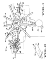
- FIG. 1 A transfer station and transfer mechanism incorporating the preferred construction fulfilling the mode of operation of the present invention, is shown in Figure 1 and is generally identified by the numeral 10.
- Thermoplastic web material W being folded along a line spaced from its longitudinal median to produce uneven edges is passed between upper and lower draw rolls 12 and 14 respectively, which are in forceable contact creating nip pressure to feed the web material in the direction indicated by the arrow.
- a reciprocating seal bar 16 Longitudinally adjacent to the draw rolls a reciprocating seal bar 16, cooperates with a platen or seal roll 18 to sever and seal a portion of web material which is projected between the seal bar and the platen roll when the seal bar is in its raised position.
- upper and lower stripper fingers 20 and 22 residing in slots or undercuts 24 and 26 formed at equally spaced intervals in each of the draw rolls (Fig. 3).
- a slightly downwardly inclined grid-like support or table 28 is provided for supporting an advanced portion of the web which will constitute a bag B created when the seal bar 16 moves downwardly in pressure engagement with the platen or seal roll 18.
- Figure 2 depicts a completed bag which includes side welds SW, a lip L and 2 wicket pin receiving holes H.
- a bag on the table or support 28 is transferred by transfer mechanism 30 in a circular arc to a stacking stacking station SS which includes upwardly projecting pins or posts 32 rigidly connected to a supporting plate 34.
- the supporting plates 34 are attached to a chain conveyor 35 wrapped around a sprocket 37.
- the conveyor 35 carries a plurality of plates 34 and a drive advances the upper reach of the conveyor to the right (Fig. 1) moving a plate carrying a complete bag stack away from stacking station SS and positioning a successive plate at the stacking station so that another bag stack can be produced. It will be observed that the stacking station illustrates a bag stack being generated on the posts 32.
- the transfer mechanism 30 whose construction and mode operation is conventional in the art will be briefly described to integrate its operation with the present disclosure.
- the transfer mechanism comprises a transverse support shaft 36 mounting at each end enlarged hollow hubs 38 being connected to a source of vacuum.
- Each hub has rigidly connected to its outer circular periphery a series radially extending equally circumferentially spaced hollow bars 40 provided, on a selected surface, with a series of holes 42 extending for substantially the entire length of the surface.
- the surface of the bars 40, having the holes 42 form therein are the leading surfaces with respect to the clockwise rotation indicated by the arrow R in Figure 1 so that in passing the surface of the table 28 the bag lying thereon is grasped or held firmly due to the blockage of selected holes 42 and the attendant pressure difference resulting therefrom.
- the rate at which successive bags are deployed on the support table 28 is equal to the rate at which successive pairs of arms approach, engage and transfer a bag from the transfer station TS to the stacking station SS.
- Figures 1 and 5 show a bag carried by each pair of arms as they recede from the transfer station TS and approach the stacking station SS.
- Synchronized rotation of the transfer mechanism 30 is achieved by connecting its drive to the drive of the bag machine. Portions of the drive is shown in Figure 1 where a pinion gear 44 drives, through an idler gear 46, a large gear 48 mounted on a shaft 50, a gear pulley 52 driving a gear pulley 54 fixed to the shaft 36 by cogbelt 56.
- means are provided for maintaining the portion of the web W advanced to the table 28 in a flat wrinkle-free condition during its advance and during the time of its momentary repose on the table 28 to insure that its flat condition is maintained when the completed bag B is gripped by a pair of arms 40 of the transfer device 30.
- Such means comprise cyclically operable means 58, including lower stripper fingers 22, for creating a curtain of high velocity air below the path of the web W to establish 2 principal concurrent conditions: 1) reduce the static pressure between the web W and the table 28 and 2) to "stiffen" the advancing web portion to prevent or remove wrinkles that may develop.
- the first of said conditions creates a differential static pressure between the upper and lower surfaces of the web and thereby establishes a net force tending to urge the advancing web portion toward the table 28 while at the same time stiffening occurs by virtue of a plurality of spaced apart high velocity air streams tending to corrugate and thus stiffen the advancing web segment.
- Each of the lower stripper fingers 22 are in the form of a tubular conduit having a slight arcuate bend as illustrated.
- One end of the fingers are connected to transversely extending air supply manifold 60 which is supported in any suitable manner to the frame of the machine.
- air is admitted to the manifold 60 during a portion of every machine cycle by machine timed valves which are conventional in the art.
- the preferred sequence of operation of admitting or connecting the manifold 60 to the supply of pressure air is initiated when the leading edge of the web being advanced to the support table 28 is at least 1-1/4 inches beyond the edge of the table adjacent to the platen or seal roll 18 and is terminated when the tip 62 of a heated seal bar 64 is just above the lower end of a liquid cooled heat shield 66.
- the air blow down means comprise an upper and lower manifold 74 and 76, respectively, and each of the manifolds carries a plurality of regularly laterally spaced nozzles 78.
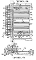
- the support of table 28 is built up from a plurality of longitudinally extending metal strips 80 having their ends joined to transversely extending strips 82.
- the strip 82 adjacent the platen or seal roll 18 is formed with a substantially 90° flange 84 defining an extension of the upper surface of table 28 and a lower oblique flange 86.
- the metal strip 82 formed as described serves to prevent the creation of misdirected air currents which may interfere with maintaining the flatness of the bag B.
- the strip 98 is formed with a plurality of slots 102 directed in a generally oblique direction as indicated by the arrow 104 and providing a channel for the air issuing from the holes 94.
- the strip 100 is secured to the slotted strip 98 and thereby defines a passageway directing the air discharged through the holes 94 substantially in the direction indicated by the arrow 104.
- the strip 100 provides a smooth upper surface coplanar with the upper surface of the metal strips 80 insuring that no hinderance is encountered by the thermoplastic web when it is projected on the table 28 by the draw rolls 12 and 26.
- the top and bottom of a bag deployed on the table 28 not only overlies the chambers 88 and 90 but extend slightly beyond the upper partitions 96 sufficiently to be engaged by the hollow bars 40 of the transfer mechanism 30.
- High velocity air issuing from the slots 102 and directed in the direction indicated by the arrows 104 not only create a drop in static pressure below that of ambient conditions and thereby retain the bag in the illustrated position but also have the tendency to dissipate irregularities (creases, waviness, etc.) in the ends of the bag which will be engaged by the bars 40. This of course ensures that on being grasped by the bars 40 the bag will assume a substantially planar condition.
- an air shield 112 taking the form of a flat plate of metal or plastic, is mounted to lie in a vertical plane adjacent the path of the bars 40 that engage the bag lip L.
- the plate 112 controls the air currents such that the lip L of the bag is maintained sufficiently flat to achieve proper pickup by the transfer arms 40.
- a stationary air baffel 114 extends between the hubs 38 and is formed with an arcuate bent portion producing an upwardly inclined panel 116 and a downwardly extending panel 118. By virtue its location and its configuration the baffel 114 directs currents of high velocity air issuing from the nozzles 78 and from the lower stripper fingers 22 downwardly not only blocking air currents that may disturb bags which are in the process of being transferred, but also the bags which are stacked on a pins 32.
Landscapes
- Engineering & Computer Science (AREA)
- Mechanical Engineering (AREA)
- Making Paper Articles (AREA)
Description
- This invention relates to an apparatus for processing thermoplastic web that is intermittently unwound from a web roll; for making equally spaced pairs of holes adjacent one edge of the web; for sealing and severing equal increments of the web along a line transverse to the direction of web advance to thereby produce web segments of equal dimensions and such that each segment contains a pair of said holes.
- The subject-matter of the invention is defined in the accompanying Claim 1. According to the precharacterizing part of Claim 1 the aforesaid apparatus comprises means for supporting the leading advanced web increment before and following severance, means operable during advance of the web for directing high velocity air streams in the direction of web advance and between the path of the web and said supporting means, means for directing high velocity air streams derived from nozzles located below and adjacent the ends of the web segment parallel to the direction of web advance, and means for transferring and stacking the segments onto pins such that the pins project through the pairs of holes, said transferring means including a plurality of radially extending circumferentially spaced transverse pairs of hollow arms provided with holes communicating with a source of vacuum; and means for rotating said arms in synchronism with the intermittent advance of the web with said arms describing a path straddling the supporting means to grasp successive web segments and transport the segments held thereby in a circular arc onto the pins.
- Apparatus having these features are already known from US-A-4 260 147 and US-A-4 286 907.
- According to the characterizing part of the accompanying Claim 1 the apparatus of the present invention also includes a stationary air baffel adjacent said supporting means for deflecting the air currents created by the airstreams away from the path in which the segments are transferred and placed on the pins.
- Figure 1 is an elevation illustrating the draw rolls, the sealing and severing station, the transfer station, the transfer mechanism and the stacking station of a typical bag machine,
- Figure 2 is a perspective of a typical lipped bag,
- Figure 3 is a partial plan of Figure 1 illustrating certain details of the stacking station,
- Figure 4 is a cross section of Figure 3 taken substantially along the line 4-4,
- Figure 5 is a diagrammatic perspective of Figure 1, and
- Figure 6 is a section taken along the line 6-6 of Figure 5.
- A transfer station and transfer mechanism incorporating the preferred construction fulfilling the mode of operation of the present invention, is shown in Figure 1 and is generally identified by the
numeral 10. Thermoplastic web material W being folded along a line spaced from its longitudinal median to produce uneven edges is passed between upper andlower draw rolls seal bar 16, cooperates with a platen orseal roll 18 to sever and seal a portion of web material which is projected between the seal bar and the platen roll when the seal bar is in its raised position. Associated with the draw rolls and serving to ensure that the web follows a linear path are upper andlower stripper fingers - Adjacent to the seal roll 18 a slightly downwardly inclined grid-like support or table 28 is provided for supporting an advanced portion of the web which will constitute a bag B created when the
seal bar 16 moves downwardly in pressure engagement with the platen orseal roll 18. Figure 2 depicts a completed bag which includes side welds SW, a lip L and 2 wicket pin receiving holes H. A bag on the table orsupport 28 is transferred bytransfer mechanism 30 in a circular arc to a stacking stacking station SS which includes upwardly projecting pins orposts 32 rigidly connected to a supportingplate 34. The supportingplates 34 are attached to achain conveyor 35 wrapped around asprocket 37. Theconveyor 35 carries a plurality ofplates 34 and a drive advances the upper reach of the conveyor to the right (Fig. 1) moving a plate carrying a complete bag stack away from stacking station SS and positioning a successive plate at the stacking station so that another bag stack can be produced. It will be observed that the stacking station illustrates a bag stack being generated on theposts 32. - The
transfer mechanism 30 whose construction and mode operation is conventional in the art will be briefly described to integrate its operation with the present disclosure. Essentially, the transfer mechanism comprises a transverse support shaft 36 mounting at each end enlargedhollow hubs 38 being connected to a source of vacuum. Each hub has rigidly connected to its outer circular periphery a series radially extending equally circumferentially spacedhollow bars 40 provided, on a selected surface, with a series ofholes 42 extending for substantially the entire length of the surface. As shown in Figure 3 the surface of thebars 40, having theholes 42 form therein are the leading surfaces with respect to the clockwise rotation indicated by the arrow R in Figure 1 so that in passing the surface of the table 28 the bag lying thereon is grasped or held firmly due to the blockage of selectedholes 42 and the attendant pressure difference resulting therefrom. - The rate at which successive bags are deployed on the support table 28 is equal to the rate at which successive pairs of arms approach, engage and transfer a bag from the transfer station TS to the stacking station SS. Figures 1 and 5 show a bag carried by each pair of arms as they recede from the transfer station TS and approach the stacking station SS.
- Synchronized rotation of the
transfer mechanism 30 is achieved by connecting its drive to the drive of the bag machine. Portions of the drive is shown in Figure 1 where apinion gear 44 drives, through anidler gear 46, alarge gear 48 mounted on ashaft 50, agear pulley 52 driving agear pulley 54 fixed to the shaft 36 bycogbelt 56. - In accordance with the primary objective of this invention means are provided for maintaining the portion of the web W advanced to the table 28 in a flat wrinkle-free condition during its advance and during the time of its momentary repose on the table 28 to insure that its flat condition is maintained when the completed bag B is gripped by a pair of
arms 40 of thetransfer device 30. Such means comprise cyclically operable means 58, includinglower stripper fingers 22, for creating a curtain of high velocity air below the path of the web W to establish 2 principal concurrent conditions: 1) reduce the static pressure between the web W and the table 28 and 2) to "stiffen" the advancing web portion to prevent or remove wrinkles that may develop. The first of said conditions creates a differential static pressure between the upper and lower surfaces of the web and thereby establishes a net force tending to urge the advancing web portion toward the table 28 while at the same time stiffening occurs by virtue of a plurality of spaced apart high velocity air streams tending to corrugate and thus stiffen the advancing web segment. - Each of the
lower stripper fingers 22 are in the form of a tubular conduit having a slight arcuate bend as illustrated. One end of the fingers are connected to transversely extendingair supply manifold 60 which is supported in any suitable manner to the frame of the machine. As indicated previously air is admitted to themanifold 60 during a portion of every machine cycle by machine timed valves which are conventional in the art. The preferred sequence of operation of admitting or connecting themanifold 60 to the supply of pressure air is initiated when the leading edge of the web being advanced to the support table 28 is at least 1-1/4 inches beyond the edge of the table adjacent to the platen orseal roll 18 and is terminated when thetip 62 of aheated seal bar 64 is just above the lower end of a liquid cooledheat shield 66. - In addition to the curtain of air supplied by the
stripper fingers 22 streams of high velocity air issuing from depressing or air blow down means 68 producing high velocity air blankets impinging the advancing portion of the web at longitudinally spaced intervals. A descriptive illustration of this condition is shown in Figure 5 by the pairs ofvectors vectors 70 impinge on the bag or web segment toward its leading edge while thevectors 72 impinge upon the bag near the trailing seal. - The air blow down means comprise an upper and
lower manifold nozzles 78. - As shown most clearly in Figure 5 the support of table 28 is built up from a plurality of longitudinally extending
metal strips 80 having their ends joined to transversely extendingstrips 82. As illustrated in Figure 4 thestrip 82 adjacent the platen orseal roll 18 is formed with a substantially 90°flange 84 defining an extension of the upper surface of table 28 and a loweroblique flange 86. Themetal strip 82 formed as described serves to prevent the creation of misdirected air currents which may interfere with maintaining the flatness of the bag B. - While the air currents issuing from the
manifolds lower stripper fingers 22 maintain a major portion of the bag substantially flat, means are provided for ensuring flatness of the ends of the bag which define the bottom and the mouth. To achieve and maintain flatness the opposed longitudinal ends of the table 28 are provided withextensions 88 and 90 each of which define a chamber connected to a source of pressure air byconduits 92 one of which is shown in Figure 4. Each chamber is formed with a plurality ofholes 94 through which air is discharged. Figure 6 shows the details of construction of thechamber 88 which takes the form of a generally rectangular housing having theholes 94 in itsupper partition 96 which is extended to provide support for the opposed end portions of a bag and to direct air issuing from theholes 94. Overlying theupper partition 96 are two flat strips of metal or othersuitable material strip 98 is formed with a plurality ofslots 102 directed in a generally oblique direction as indicated by thearrow 104 and providing a channel for the air issuing from theholes 94. Thestrip 100 is secured to theslotted strip 98 and thereby defines a passageway directing the air discharged through theholes 94 substantially in the direction indicated by thearrow 104. Moreover, thestrip 100 provides a smooth upper surface coplanar with the upper surface of themetal strips 80 insuring that no hinderance is encountered by the thermoplastic web when it is projected on the table 28 by thedraw rolls - As shown in Figure 5 the top and bottom of a bag deployed on the table 28 not only overlies the
chambers 88 and 90 but extend slightly beyond theupper partitions 96 sufficiently to be engaged by thehollow bars 40 of thetransfer mechanism 30. High velocity air issuing from theslots 102 and directed in the direction indicated by thearrows 104 not only create a drop in static pressure below that of ambient conditions and thereby retain the bag in the illustrated position but also have the tendency to dissipate irregularities (creases, waviness, etc.) in the ends of the bag which will be engaged by thebars 40. This of course ensures that on being grasped by thebars 40 the bag will assume a substantially planar condition. - To achieve the objective of insuring that each bag is retained by each
stacking post 32 it is essential that the bag lip overlying thechamber 88 is flat and smooth. Contributing to the attainment of this condition anair shield 112, taking the form of a flat plate of metal or plastic, is mounted to lie in a vertical plane adjacent the path of thebars 40 that engage the bag lip L. Theplate 112 controls the air currents such that the lip L of the bag is maintained sufficiently flat to achieve proper pickup by thetransfer arms 40. - Air discharged by the
lower stripper fingers 22 and thenozzles 78 attached to themanifolds post 32, astationary air baffel 114 extends between thehubs 38 and is formed with an arcuate bent portion producing an upwardly inclined panel 116 and a downwardly extendingpanel 118. By virtue its location and its configuration thebaffel 114 directs currents of high velocity air issuing from thenozzles 78 and from thelower stripper fingers 22 downwardly not only blocking air currents that may disturb bags which are in the process of being transferred, but also the bags which are stacked on apins 32. - According to the above description, it should be evident that providing a combination of air streams to the upper and lower surface of its own plastic bag, it assumes a generally wrinkle free flat condition which enhances proper pickup by the
transfer mechanism 30 and thereby depositing the completed bag properly on bothposts 32 at the stacking station.
Claims (5)
Applications Claiming Priority (2)
| Application Number | Priority Date | Filing Date | Title |
|---|---|---|---|
| US539789 | 1983-10-07 | ||
| US06/539,789 US4573955A (en) | 1983-10-07 | 1983-10-07 | Apparatus for stacking thermoplastic sheets |
Publications (4)
| Publication Number | Publication Date |
|---|---|
| EP0141287A2 EP0141287A2 (en) | 1985-05-15 |
| EP0141287A3 EP0141287A3 (en) | 1985-11-27 |
| EP0141287B1 true EP0141287B1 (en) | 1989-12-20 |
| EP0141287B2 EP0141287B2 (en) | 1993-10-20 |
Family
ID=24152652
Family Applications (1)
| Application Number | Title | Priority Date | Filing Date |
|---|---|---|---|
| EP84111906A Expired - Lifetime EP0141287B2 (en) | 1983-10-07 | 1984-10-04 | Improvements in stacking thermoplastic sheets |
Country Status (7)
| Country | Link |
|---|---|
| US (1) | US4573955A (en) |
| EP (1) | EP0141287B2 (en) |
| AU (1) | AU566536B2 (en) |
| BR (1) | BR8405041A (en) |
| CA (1) | CA1226311A (en) |
| DE (1) | DE3480789D1 (en) |
| GB (1) | GB2147572B (en) |
Families Citing this family (22)
| Publication number | Priority date | Publication date | Assignee | Title |
|---|---|---|---|---|
| US4668148A (en) * | 1985-06-27 | 1987-05-26 | Fmc Corporation | Sheet stacking and transferring device |
| US4850781A (en) * | 1986-11-03 | 1989-07-25 | Fmc Corporation | Zero cycle interrupt wicket stacker |
| CA1291771C (en) * | 1986-11-03 | 1991-11-05 | Rene F. Debin | Zero cycle interrupt wicket stacker |
| DE3808764A1 (en) * | 1988-03-16 | 1989-09-28 | Albert Hettler | Depositing device for plastic bags |
| GB2226427B (en) * | 1988-11-10 | 1993-03-24 | Fmc Corp | Servo drive bag machine |
| US5230688A (en) * | 1988-11-14 | 1993-07-27 | Fmc Corporation | Servo driven components of a bag machine |
| DE4000450C2 (en) * | 1989-01-09 | 2000-01-13 | Fmc Corp | Method and device for stacking bags |
| DE3923778A1 (en) * | 1989-07-18 | 1991-01-31 | Windmoeller & Hoelscher | DEVICE FOR TRANSPORTING A PREFERRED, MULTILAYERED TRAIN OF THERMOPLASTIC PLASTIC |
| US5074735A (en) * | 1990-09-07 | 1991-12-24 | Amplas, Inc. | Wicketing apparatus |
| US5376219A (en) * | 1991-09-26 | 1994-12-27 | Sealed Air Corporation | High speed apparatus for forming foam cushions for packaging purposes |
| US6003288A (en) * | 1992-02-28 | 1999-12-21 | Sealed Air Corporation | Compact packaging device for forming foam filled cushions for packaging purposes |
| US5807228A (en) * | 1995-01-13 | 1998-09-15 | F. L. Smithe Machine Company, Inc. | Sheet folding method and apparatus |
| US5672235A (en) * | 1995-10-05 | 1997-09-30 | Amplas, Inc. | Plastic film stripper apparatus and method for heated sealing apparatus |
| DE29619463U1 (en) * | 1996-11-08 | 1998-03-05 | Sachsenring Entwicklungsgesell | Device for removing a thin, flat, flexible section from a shelf |
| US5785794A (en) * | 1997-03-05 | 1998-07-28 | Fmc Corporation | Seal roll index |
| US6703537B1 (en) * | 1997-11-15 | 2004-03-09 | The Procter & Gamble Company | Absorbent article having improved fecal storage structure |
| DE19848412C2 (en) * | 1998-10-21 | 2001-03-01 | Lemo Maschb Gmbh | Device for producing bags, sacks or the like from a thermoplastic plastic sheet |
| DE10136867A1 (en) * | 2001-07-28 | 2003-02-20 | Lemo Maschb Gmbh | Assembly to transfer plastics bags to a gathering station, at a bag production machine, has vane arms with interior suction channels, and suction openings at a suction surface |
| DE10151576B4 (en) * | 2001-10-23 | 2010-04-15 | Lemo Maschinenbau Gmbh | Device for welding plastic films |
| DE102004054044B4 (en) * | 2004-11-05 | 2016-06-16 | Manroland Web Systems Gmbh | Method and device for transporting flat products |
| US7624980B2 (en) * | 2007-07-09 | 2009-12-01 | Pearl Technologies Incorporated | Tool-less rotary vacuum wicketter assembly |
| US20230249428A1 (en) * | 2022-02-09 | 2023-08-10 | Paper Converting Machine Company | Method of Aligning Air Burst on Bag Wicketer Processing Line |
Family Cites Families (9)
| Publication number | Priority date | Publication date | Assignee | Title |
|---|---|---|---|---|
| DE468077C (en) * | 1925-05-15 | 1928-11-07 | Georg Spiess | Method and device for aligning sheets or similar work goods, in particular when feeding them to printing machines, folding machines or similar work machines |
| GB388234A (en) * | 1932-03-02 | 1933-02-23 | Schnellpressenfab Heidelberg | Improvements in and relating to platen printing presses |
| US2769495A (en) * | 1953-07-01 | 1956-11-06 | John Waldron Corp | Web cutting and sheet delivery and stacking mechanism |
| DE2358206C3 (en) * | 1973-11-22 | 1979-10-04 | Roland Offsetmaschinenfabrik Faber & Schleicher Ag, 6050 Offenbach | Device on printing machines for transporting sheets |
| US3971554A (en) * | 1975-01-09 | 1976-07-27 | Xerox Corporation | Sheet stacker |
| GB2055087A (en) * | 1977-07-01 | 1981-02-25 | Gao Ges Automation Org | Feeding and smoothing sheet material |
| US4286907A (en) * | 1979-09-17 | 1981-09-01 | Gloucester Engineering Co., Inc. | Grid extensions on a rotary stacker |
| GB2032399B (en) * | 1979-10-04 | 1982-11-10 | Crown Zellerbach Corp | Apparatus for and a method of directing a flexible web |
| DE3107883C2 (en) * | 1981-03-02 | 1985-06-20 | Windmöller & Hölscher, 4540 Lengerich | Device for stacking flat objects such as hose sections, bags or sacks |
-
1983
- 1983-10-07 US US06/539,789 patent/US4573955A/en not_active Expired - Fee Related
-
1984
- 1984-10-02 AU AU33765/84A patent/AU566536B2/en not_active Ceased
- 1984-10-03 CA CA000464691A patent/CA1226311A/en not_active Expired
- 1984-10-04 GB GB08425122A patent/GB2147572B/en not_active Expired
- 1984-10-04 EP EP84111906A patent/EP0141287B2/en not_active Expired - Lifetime
- 1984-10-04 DE DE8484111906T patent/DE3480789D1/en not_active Expired - Lifetime
- 1984-10-05 BR BR8405041A patent/BR8405041A/en not_active IP Right Cessation
Also Published As
| Publication number | Publication date |
|---|---|
| AU566536B2 (en) | 1987-10-22 |
| EP0141287A3 (en) | 1985-11-27 |
| EP0141287B2 (en) | 1993-10-20 |
| DE3480789D1 (en) | 1990-01-25 |
| GB8425122D0 (en) | 1984-11-07 |
| BR8405041A (en) | 1985-08-20 |
| CA1226311A (en) | 1987-09-01 |
| GB2147572B (en) | 1987-03-18 |
| EP0141287A2 (en) | 1985-05-15 |
| AU3376584A (en) | 1985-04-18 |
| US4573955A (en) | 1986-03-04 |
| GB2147572A (en) | 1985-05-15 |
Similar Documents
| Publication | Publication Date | Title |
|---|---|---|
| EP0141287B1 (en) | Improvements in stacking thermoplastic sheets | |
| US4268346A (en) | Apparatus for making tank top bags from a web of tubular plastics film provided with side folds | |
| US4493684A (en) | Method for making partially separated multibags | |
| US3633731A (en) | Bag wicketter | |
| GB2146575A (en) | The manufacture of thermoplastic bags | |
| US4083747A (en) | Apparatus for making stacks of plastics bags | |
| US2772880A (en) | Sheet stacker | |
| JPH01294406A (en) | Packaging machine | |
| JPS6212577A (en) | Method and device for folding endless band-shaped material to zigzag shape | |
| JPS58181631A (en) | Method and device for manufacturing and piling bag consisting of thermoplastic plastic | |
| EP0050339B1 (en) | Thermoplastic bag stacking apparatus | |
| US4133252A (en) | Method and apparatus for securing carrying handles to bags | |
| US4954033A (en) | Transfer mechanism for conveyor | |
| US4706444A (en) | Apparatus for wrapping continuously moving articles with heat-shrinkable material | |
| US4106395A (en) | Method and apparatus for producing stacks of folded bags | |
| US5069659A (en) | Apparatus for the production of shopping bags having reinforced handle holes | |
| JPS6169443A (en) | Production unit for thermoplastic bag | |
| US4289567A (en) | Apparatus for applying web sections to a flat-lying workpiece | |
| JPH048348B2 (en) | ||
| US6550225B1 (en) | Method and apparatus for obtaining individual web sections from a web of sheet material | |
| US20040112014A1 (en) | Method and device for the packaging of flat objects | |
| JPH1191013A (en) | Method and equipment for manufacturing flat bottom packaging bag | |
| JP2001018904A (en) | Box sealing apparatus for bag-in-box | |
| JPS6382736A (en) | Production device for box-shaped vessel | |
| EP0644825B1 (en) | Vacuum advance system for high speed contact sealer for forming a flat film into a tube |
Legal Events
| Date | Code | Title | Description |
|---|---|---|---|
| PUAI | Public reference made under article 153(3) epc to a published international application that has entered the european phase |
Free format text: ORIGINAL CODE: 0009012 |
|
| AK | Designated contracting states |
Designated state(s): BE DE FR GB IT |
|
| PUAL | Search report despatched |
Free format text: ORIGINAL CODE: 0009013 |
|
| AK | Designated contracting states |
Designated state(s): BE DE FR GB IT |
|
| 17P | Request for examination filed |
Effective date: 19860523 |
|
| 17Q | First examination report despatched |
Effective date: 19870121 |
|
| GRAA | (expected) grant |
Free format text: ORIGINAL CODE: 0009210 |
|
| AK | Designated contracting states |
Kind code of ref document: B1 Designated state(s): BE DE FR GB IT |
|
| ITF | It: translation for a ep patent filed |
Owner name: SOCIETA' ITALIANA BREVETTI S.P.A. |
|
| ET | Fr: translation filed | ||
| REF | Corresponds to: |
Ref document number: 3480789 Country of ref document: DE Date of ref document: 19900125 |
|
| PLBI | Opposition filed |
Free format text: ORIGINAL CODE: 0009260 |
|
| 26 | Opposition filed |
Opponent name: WINDMOELLER & HOELSCHER Effective date: 19900920 |
|
| ITTA | It: last paid annual fee | ||
| PUAH | Patent maintained in amended form |
Free format text: ORIGINAL CODE: 0009272 |
|
| STAA | Information on the status of an ep patent application or granted ep patent |
Free format text: STATUS: PATENT MAINTAINED AS AMENDED |
|
| ITF | It: translation for a ep patent filed |
Owner name: SOCIETA' ITALIANA BREVE |
|
| PGFP | Annual fee paid to national office [announced via postgrant information from national office to epo] |
Ref country code: FR Payment date: 19930915 Year of fee payment: 10 |
|
| PGFP | Annual fee paid to national office [announced via postgrant information from national office to epo] |
Ref country code: GB Payment date: 19930920 Year of fee payment: 10 |
|
| PGFP | Annual fee paid to national office [announced via postgrant information from national office to epo] |
Ref country code: BE Payment date: 19930928 Year of fee payment: 10 |
|
| 27A | Patent maintained in amended form |
Effective date: 19931020 |
|
| AK | Designated contracting states |
Kind code of ref document: B2 Designated state(s): BE DE FR GB IT |
|
| ET3 | Fr: translation filed ** decision concerning opposition | ||
| PG25 | Lapsed in a contracting state [announced via postgrant information from national office to epo] |
Ref country code: GB Effective date: 19941004 |
|
| PG25 | Lapsed in a contracting state [announced via postgrant information from national office to epo] |
Ref country code: BE Effective date: 19941031 |
|
| BERE | Be: lapsed |
Owner name: FMC CORP. Effective date: 19941031 |
|
| GBPC | Gb: european patent ceased through non-payment of renewal fee |
Effective date: 19941004 |
|
| PG25 | Lapsed in a contracting state [announced via postgrant information from national office to epo] |
Ref country code: FR Effective date: 19950630 |
|
| REG | Reference to a national code |
Ref country code: FR Ref legal event code: ST |
|
| PGFP | Annual fee paid to national office [announced via postgrant information from national office to epo] |
Ref country code: DE Payment date: 19951027 Year of fee payment: 12 |
|
| PG25 | Lapsed in a contracting state [announced via postgrant information from national office to epo] |
Ref country code: DE Effective date: 19970701 |