EP0141258A2 - Winding apparatus for forming a cotton wool package - Google Patents
Winding apparatus for forming a cotton wool package Download PDFInfo
- Publication number
- EP0141258A2 EP0141258A2 EP84111525A EP84111525A EP0141258A2 EP 0141258 A2 EP0141258 A2 EP 0141258A2 EP 84111525 A EP84111525 A EP 84111525A EP 84111525 A EP84111525 A EP 84111525A EP 0141258 A2 EP0141258 A2 EP 0141258A2
- Authority
- EP
- European Patent Office
- Prior art keywords
- calender
- calender rolls
- winding apparatus
- winding
- rolls
- Prior art date
- Legal status (The legal status is an assumption and is not a legal conclusion. Google has not performed a legal analysis and makes no representation as to the accuracy of the status listed.)
- Granted
Links
Images


Classifications
-
- D—TEXTILES; PAPER
- D01—NATURAL OR MAN-MADE THREADS OR FIBRES; SPINNING
- D01G—PRELIMINARY TREATMENT OF FIBRES, e.g. FOR SPINNING
- D01G27/00—Lap- or sliver-winding devices, e.g. for products of cotton scutchers, jute cards, or worsted gill boxes
- D01G27/02—Lap- or sliver-winding devices, e.g. for products of cotton scutchers, jute cards, or worsted gill boxes with lap-roll or the like loaded to provide firm packages
-
- Y—GENERAL TAGGING OF NEW TECHNOLOGICAL DEVELOPMENTS; GENERAL TAGGING OF CROSS-SECTIONAL TECHNOLOGIES SPANNING OVER SEVERAL SECTIONS OF THE IPC; TECHNICAL SUBJECTS COVERED BY FORMER USPC CROSS-REFERENCE ART COLLECTIONS [XRACs] AND DIGESTS
- Y10—TECHNICAL SUBJECTS COVERED BY FORMER USPC
- Y10S—TECHNICAL SUBJECTS COVERED BY FORMER USPC CROSS-REFERENCE ART COLLECTIONS [XRACs] AND DIGESTS
- Y10S242/00—Winding, tensioning, or guiding
- Y10S242/917—Accommodating special material or article, e.g. antenna
- Y10S242/918—Web material, e.g. thermal insulation
Definitions
- the invention relates to a winding apparatus for forming cotton rolls with at least one rotating winding roll and a certain number of calender rolls for compressing a layer of cotton into a rollable cotton web.
- Cotton wraps serve as a template for the sweeping section and for the subsequent combing process.
- Calender rollers are used to press a wad of cotton in order to be able to unwind the wad of cotton without mutual felting of the wad of cotton.
- the cotton web In order to obtain a good pressing, the cotton web should be subjected to at least two pressings before the roll is formed.
- the circumferential speed of the calender rolls can be increased somewhat from roll to roll in order to accommodate the lengthening of the cotton web caused by the pressing and to obtain a small stretching of the cotton web from press passage to press passage.
- the stretching of the cotton web mentioned advantageously takes place with simultaneous contact of the cotton web with the respective calender roll, in order thereby to guide the fibers, i.e. to give a so-called stroking effect and a so-called spring back (also called breathing), i.e. to avoid partial destruction of a previous pressing.
- a roll formed around a calender roll can be removed from the calender rolls which are at rest without further movement.
- the cotton can be inserted between the first two calender rolls and then by moving the calender rolls from the rest position to the work position in the work position before the calender rolls are started.
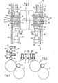
- a winding apparatus 1 (FIG. 1) comprises a first winding roller 2 and a second winding roller 3 for receiving a winding tube 4, respectively the one that is accommodated on the tube 4 Winding (not shown).
- Calender rolls 5 to 8 are arranged in front of the first winding roll 2, the calender roll 5 being referred to as the first, the calender roll 6 as the second, the calender roll 7 as the third and the calender roll 8 as the last calender roll.
- the winder is covered by a hood 9.
- the calender rolls 5 to 8 are each carried by means of two pairs of springs 10, which each consist of two spring struts 11 and 12 designed as leaf springs.
- Each pair of springs 10 is firmly connected on the one hand to a carrier 13 and on the other hand to a bearing body 14 receiving a shaft end of the calender rolls by means of screws 15.
- the carrier 13 is divided into a part 13A for receiving the screws 15 and a part 13B, which is provided with a connection surface 16 and with two threaded holes 17 for receiving screws 18 (FIG. 2).
- the carriers 13 are fastened to side walls 19 and 20 of the winding apparatus 1 in such a way that the connection surfaces 16 (FIG. 10) each abut these walls. Furthermore, the calender rolls are fastened to these walls 19 and 20 by means of these supports 13 such that the axes of rotation 21 of the calender rolls 5 to 8 each lie parallel to the rotation axis 22 of the first winding roll 2. In Figures 1 to 4 only one carrier 13 is shown per calender roll.
- calender rolls 5 to 8 in a rest position (also called a starting position), in which they have a mutual distance D of approximately 3 mm.
- a distance E provided between the last calender roll 8 and the first winding roll 2 in this rest position of the calender roll is also approximately 3 mm.
- the invention is not limited to maintaining this 3 mm for the distances D and E, larger or possibly somewhat smaller distances can also be useful for the loosening of the winding on calender rolls. In this rest position, there is a balance between the sum of the spring forces per calender roll at both ends of the calender roll and the yalander roll weight.
- D is a spring legs 11 and 12 connected by means of screws 15 fixed to the supports 13 respectively with the bearing bodies 14, have a pair of springs that is known from the strength of materials'Rechteckfeder' characteristic, that is, the deflection characteristic corresponds approximately to the deflection characteristic of the 'rectangular springs' .
- the positions of the supports 13 on the side walls 19 and 20 are shifted until the desired distance D has the desired dimension over the entire length of the calender roll.
- the cylinder 23 is supported on both sides of the calender rolls on a support 25 fastened to the corresponding wall 19 or 20 (FIG. 2, only indicated schematically in FIG. 1).
- a piston head 27 belonging to the piston 26 of the cylinder 23 bears against the leaf spring 11 relating to the calender roll 5.
- the piston head 27 is designed to be U-shaped in order to be able to rest on both sides of the screw head of the screw 15 on the leaf spring 11, as shown in FIG.
- the stop means 24 each consist of a support 28 fastened to the side wall 19 or 20 (FIG. 2, only shown schematically in FIG. 1) and an associated screw 29.
- This screw 29 serves, as can be seen from FIGS. 1 and 2, as a stop, by means of which the movement of the last calender roll 8 is stopped in such a way that said distance E does not become small in the working position of the calender rolls becomes less than approx. 0.2 mm, ie at least remains so that there is no contact between the calender roll 8 and the first winding roll 2.
- the head of the screw 15, the corresponding strut abuts the screw 29.
- the distance E can be adjusted by turning the screw 29.
- FIGS. 3 and 4 show that the use of the spring-loaded calender roller guide means shown in FIG. 1 is not restricted to the arrangements shown in FIG. 1, but in a vertical arrangement (FIG. 3) or a horizontal arrangement (FIG. 4 ) can be used.
- the calender rolls in these figures are numbered in the same order as in FIG. 1.
- FIGS. 5 to 7, in which it is shown how a cotton web 30 is brought over the calender rolls 5 to 8 and then over the first winding roll 2 and finally to the winding tube 4.
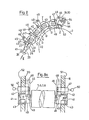
- FIGS. 8 to 11 show variants of the calender roll guide means according to the invention. The same elements therefore have the same reference numerals.
- the bearing bodies 40 are guided in a guide track 41 (FIG. 8A, only indicated schematically in FIG. 8), consisting of an upper guide rail 42 and a lower guide rail 43.
- the peripheral surface 44 of the bearing body 40 is accordingly adapted to the rails and is, for example, circular and has one for sliding between the This surface and the guide rails suitable fineness and width B (Fig. 8A).
- the guide track 41 comprises a stop bar 45 (FIG. 8A).
- the swivel arms 46 are each pivotably mounted in the side walls 19 by a bolt 48 and are pivoted clockwise until the guideway is free in order to enable the introduction of the calender rolls or their bearing bodies 40 into the guideway 41.
- the latches 47 are therefore displaceably guided in the side walls 19 and 20 in such a way that they can be displaced from a starting position in which the stop lugs 49 rest against the side wall 19 and 20 in a working position in which the stop lug 49, as in FIG 8a, lies in front of the swivel arm 46, whereby the swiveling back of the swivel arm 46 in the clockwise direction is prevented.
- the bolts 47 are further provided with a handle 50 (FIG. 8a) and with a stop (not shown). The latter serves for the correct positioning of the bolt and, in the working position of the bolt, rests on the outer surface 51 of the side wall 19, or on the outer surface 52 of the side wall 20.
- the swivel arms 46 provided on both sides of the calender roller 8 require two stops, one of which is the bolt 47, and one spring 53 each, since the calender roller 8 moves downward in the guideway clockwise.
- the spring 53 is a compression spring supported on a base 56 belonging to the side walls 19 and 20 (only indicated in FIG. 8) and urges the calender roller 8 in the guideway 41 counterclockwise into the rest position in which the swivel arm 46 on the nose 49 of the latch 47 abuts.
- the distance E has a size of approximately 3 mm.
- the calender rolls 5, 6 and 7 are in the rest position due to the force of gravity (also called gravitation), which causes them to move in the counterclockwise direction in the guideway 41, by means of the swivel arms 46 on the lugs 49, the distances between the bars 47 being chosen in this way is that in this rest position, the distances D between the calender rolls are approximately 3 mm,
- the working position of the calender rolls 5 to 8 is achieved in the manner described for FIGS. 1 and 2 by means of a cylinder 23 provided on both sides of the calender rolls. Accordingly no repetition of the elements and reference to the description section for FIGS. 1 and 2, ie the same elements are identified by the same reference numerals.
- the swivel arms 46 of the last calender roll each abut against a stop screw 54 in order to ensure that the distance E in this working position of the calender rolls is at least 0.2 mm.
- the swivel arms 46 assigned to the calender roll 8 are no longer in contact with the stop lugs 49, which also applies to the swivel arms which are assigned to the calender rolls 5, 6 and 7.
- the stop screw 54 is each connected to the side wall 19 or 20 by means of a support 55, in which a thread is provided for receiving this screw, i. H.
- a swivel arm 46, a bar 47, a spring 53 and a stop screw 54 etc. are provided on each side of the calender rolls.
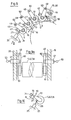
- FIGS. 9 and 9a show a further variant, similar to the variant of FIG. 8 or 8a, in which the calender rolls move in the same way due to gravity and are locked or moved in the same way by stops or springs. Accordingly, elements with the same functions have the same reference numerals as in the descriptions of the previous figures.
- the essential difference from the arrangement shown in FIGS. 8 and 8a is the guidance of the calender rolls 5 to 8 by using them pendulum arms 60 are arranged pivotally.
- the pendulum arms 60 are pivotally attached to the side walls 19 and 20 by means of bolts 48 and accommodate the bearing bodies 61 of the calender rollers 5 to 8.
- the latches 47, the locking screws 54, the compression springs 53 and the cylinders 23 have the same functions with the associated accessories as in the arrangement shown in FIGS. 8 and 8a. Accordingly, the pendulum arms 60 assigned to the calender rollers 8 rest in the rest position as a result of the spring pressure of the spring 53 on the lugs 49 of the latches 47. At the same time, the pendulum arms 60 assigned to the calender rolls 5, 6 and 7 bear against the corresponding lugs 49 of the bars 47 as a result of the gravity of the calender rolls. In this rest position, the distances D and the distance E have the previously mentioned dimension of approx. 3 mm.
- FIG. 10 shows a further variant of the calender roll guide in which the bearing bodies 61 are received by a resilient arm 70.
- This resilient arm 70 comprises a support beam 71 (not shown) fastened to the side walls 19 and 20, a support arm 72 and a leaf spring 73 connecting the support arm 72 to the support beam 71.
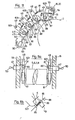
- This traction cable is guided from the piston 84 through eyelets 86 provided on the pendulum arms 601 and through a compression spring 87 provided after each eyelet and each via a roller 88 fitted between the compression springs 87 and the eyelets 86.
- the end of the traction cable 85 opposite the piston 84 becomes with connected to the end of the last compression spring 87 opposite the eyelet 86.
- a driver 89 is firmly connected to the rope.
- the length of the piston stroke must be somewhat (e.g. 5 mm) longer than the sum of all distances D (analogous to Fig. 1,8,9) and the distance E, which for the sake of clarity are not entered in Figure 11.
- the spring forces of the compression springs 87 must be greater than the spring forces of the tension springs 80 so that a displacement of the calender roll from the working position to the rest position is ensured.
- FIG. 11 shows a variant of FIG. 9 and since it is only a different arrangement of the same elements, the elements have the same reference numerals as in FIG. 9.
- the calender rolls 5 to 8 by means of the pendulum arms 60 in the rest position freely suspended.
- the cylinder 23 is activated, as described with FIG. 9, until all the calender rolls abut one another and the pendulum arms 60 assigned to the calender roll 8 bear against the stop screw 54 by the described one, which is no longer shown here Bring distance E to the desired size of 0.2 mm.
- FIG. 13 shows a variant of the arrangement shown in FIG. 8, in which the guideway 41 is shifted downwards until all the calender rollers in the guideway slide downward in the same direction by means of their gravity.
- This makes it possible to dispense with the compression spring 53 shown in FIG. 8.
- Also in this figure are there are the same elements as in Fig. 8, using the same reference numerals.
- FIG. 14 The variant shown in FIG. 14 is a similar arrangement to that in FIG. 12, with the only difference that the calender rolls are not arranged in a horizontal but in a rising straight line.
- the advantage of this arrangement over that of FIG. 12 is that it is more space-saving.
- the elements are the same as in Fig. 12 respect. 9, so that the same reference numerals have also been used here.
- 15 shows a variant of the with
- FIG. 11 shows the arrangement shown, in which, on the one hand, the cable pull 82 pulls the calender rolls from the rest position into the working position and, on the other hand, that the last calender roll 8 is arranged freely suspended.
- This rearrangement has the advantage over that of FIG. 11 that the tension springs 80 can be dispensed with.
- the cable pull 82 in exactly the same way as described for FIG. 11, has a pull cable 85, the tension springs 87, the rollers 88 and the drivers 89.
Abstract
Einen Wickelapparat (1) zum Bilden von Wattewickeln umfasst eine erste Wickelwalze (2), eine zweite Wickelwalze (3), eine Wickelhülse (4) und z.B. (vier) Kalanderwalzen (5) bis (8). Jede Kalanderwalze ist an beiden Enden mittels einem die Kalanderwalze aufnehmenden Federpaar (10) beweglich gehalten. Jedes Federpaar (10) ist am einen Ende mit dem Lagerkörper (14) der Kalanderwalzen und am anderen Ende mittels eines Trägers (13) mit den Seitenwänden des Wickelapparates fest verbunden. Ein Kolben (26) eines Pneumatikzylinders (23) schiebt die Kalanderwalzen aus einer Ruheposition, in welcher zwischen den Kalanderwalzen ein Abstand D resp. zwischen der letzten Kalanderwalze (8) und der ersten Wickelwalze (2) ein Abstand E besteht in eine Arbeitspoposition, in welcher die Kalanderwalzen, ohne dazwischen liegende Warrebahn, gegeneinander gepresst werden. Die Lage der Kalanderwalzen in der Ruheposition wird durch die Federpaare (10) gehalten.A winding apparatus (1) for forming cotton rolls comprises a first winding roll (2), a second winding roll (3), a winding tube (4) and e.g. (four) calender rolls (5) to (8). Each calender roll is movably held at both ends by means of a pair of springs (10) receiving the calender roll. Each pair of springs (10) is firmly connected at one end to the bearing body (14) of the calender rolls and at the other end by means of a carrier (13) to the side walls of the winding apparatus. A piston (26) of a pneumatic cylinder (23) pushes the calender rolls from a rest position, in which a distance D or between the calender rolls. There is a distance E between the last calender roll (8) and the first winding roll (2) in a working position in which the calender rolls are pressed against each other without a warp path in between. The position of the calender rolls in the rest position is held by the pairs of springs (10).
Description
Die Erfindung betrifft einen Wickelapparat zum Bilden von Wattewickeln mit mindestens einer rotierenden Wikkelwalze und einer bestimmten Anzahl Kalanderwalzen zum Verdichten einer Watteschicht zu einer wickelbaren Wattebahn.The invention relates to a winding apparatus for forming cotton rolls with at least one rotating winding roll and a certain number of calender rolls for compressing a layer of cotton into a rollable cotton web.
Wattewickel dienen als Vorlage für die Kehrstrecke und für den nachfolgenden Kämmprozess.Cotton wraps serve as a template for the sweeping section and for the subsequent combing process.
Kalanderwalzen dienen der Pressung einer Wattebahn, um das Wiederabwickeln des Wattewickels ohne gegenseitige Verfilzung der Wattebahnen durchführen zu können. Um eine gute Pressung zu erhalten, sollte die Wattebahn vor dem Bilden des Wickels mindestens zwei Pressungen erfahren.Calender rollers are used to press a wad of cotton in order to be able to unwind the wad of cotton without mutual felting of the wad of cotton. In order to obtain a good pressing, the cotton web should be subjected to at least two pressings before the roll is formed.
Um die Verlängerung der Wattebahn, welche durch die Pressung entsteht, aufzunehmen, und um eine kleine Verstreckung der Wattebahn von Presspassage zu Presspassage zu erhalten, kann die Umfangsgeschwindigkeit der Kalanderwalzen von Walze zu Walze etwas erhöht werden.The circumferential speed of the calender rolls can be increased somewhat from roll to roll in order to accommodate the lengthening of the cotton web caused by the pressing and to obtain a small stretching of the cotton web from press passage to press passage.
Das genannte Verstrecken der Wattebahn geschieht dabei vorteilhafterweise bei gleichzeitiger Anlage der Wattebahn an die jeweilige Kalanderwalze, um dadurch den Fasern eine Führung, d.h. einen sogenannten Streicheffekt zu geben und um ein sogenanntes Zurückfedern (auch Atmen genannt), d.h. um ein teilweises Vernichten einer vorangegangenen Pressung zu vermeiden.The stretching of the cotton web mentioned advantageously takes place with simultaneous contact of the cotton web with the respective calender roll, in order thereby to guide the fibers, i.e. to give a so-called stroking effect and a so-called spring back (also called breathing), i.e. to avoid partial destruction of a previous pressing.
Solche Kalanderwalzen-Anordnungen sind, aus dem deutschen Patent Nr. 644 119 oder dem englischen Patent Nr. 711 599 ersichtlich.Such calender roll arrangements can be seen from German Patent No. 644 119 or English Patent No. 711 599.
In diesen Patentschriften sind Kalanderwalzen in einer senkrechten Anordnung aufeinandergestapelt. Dabei ist es bekannt, dass die darin genannten Kalanderwalzen, bei welchen die Wellenlagen in Gleitschienen geführt waren, mit dem ganzen Gewicht aufeinander abgestützt waren.In these patents, calender rolls are stacked in a vertical arrangement. It is known that the calender rolls mentioned therein, in which the shaft positions were guided in slide rails, were supported on one another with their entire weight.
Diese Anordnung hatte den Nachteil, dass beim evtl. Leerlaufen der Walzen, d.h. ohne dazwischenliegende Wattebahn, einerseits die Walzen entsprechend der unterschiedlichen Umfangsgeschwindigkeit gegeneinander rieben und anderseits beim Bilden eines Wattewickels um eine Kalanderwalze, d.h. bei einer Störung, die Kalanderwalzen voneinander gehoben werden mussten, um die entsprechende Kalanderwalze wieder vom Wickel zu befreien.This arrangement had the disadvantage that when the rollers were possibly empty, i. without an interposed cotton web, on the one hand rubbing the rollers against one another according to the different peripheral speed and on the other hand when forming a cotton roll around a calender roller, i.e. in the event of a malfunction, the calender rolls had to be lifted apart in order to free the corresponding calender roll from the winding.
Um diese beiden Nachteile zu beheben oder zumindest grössten Teils zu beheben, wurde eine Anordnung der Kalanderwalzen gewählt, in welcher zwei Kalanderwalzenpaare nebeneinander angeordnet sind und die vorgenannte senkrechte Anordnung lediglich pro Walzenpaar angewendet wurde.In order to remedy these two disadvantages or at least to a large extent to remedy them, an arrangement of the calender rolls was chosen in which two calender rolls Pairs are arranged side by side and the aforementioned vertical arrangement was only used per pair of rollers.
Solche Anordnungen sind in der US Patentschrift Nr. 25 02 894 und in der deutschen Patentschrift Nr. 629 355 gezeigt.Such arrangements are shown in US Patent No. 25 02 894 and in German Patent No. 629 355.
Die durch die letztgenannte Kalanderwalzenanordnung erreichten Vorteile wurden aber mindestens teilweise mit dem erwähnten Nachteil erkauft, dass die Wattebahn in der Verstreckzone zwischen den beiden Walzenpaaren nicht mehr geführt war, was zu dem genannten "Atmen" geführt hat.The advantages achieved by the last-mentioned calender roller arrangement were, however, at least partially bought with the disadvantage mentioned that the cotton web was no longer guided in the drawing zone between the two roller pairs, which led to the "breathing" mentioned.
Erfindungsgemäss werden diese Nachteile dadurch behoben, dass die Kalanderwalzen derart geführt werden, wie dies im kennzeichnenden Teil des ersten Anspruches definiert ist.According to the invention, these disadvantages are eliminated in that the calender rolls are guided as defined in the characterizing part of the first claim.
Die weiteren vorteilhaften Ausführungsformen sind in zusätzlichen Ansprüchen beschrieben.The further advantageous embodiments are described in additional claims.
Die durch die Erfindung erreichten Vorteile sind einerseits der einfache Aufbau und die keine Reibung verursachende Führung der Kalanderwalzen.The advantages achieved by the invention are, on the one hand, the simple structure and the guidance of the calender rolls which does not cause friction.
Im weiteren kann ein sich um eine Kalanderwalze gebildeter Wickel ohne weiteres Bewegen von der sich in Ruhestellung befindlichen Kalanderwalzen entfernt werden. Ebenso kann beim Start der Maschine die Watte bei ruhenden Walzen zwischen die zwei ersten Kalanderwalzen eingeführt und anschliessend durch das Verschieben der Kalanderwalzen aus der Ruheposition in die Arbeitsposition in der Arbeitsposition festgeklemmt werden, bevor die Kalanderwalzen gestartet werden.Furthermore, a roll formed around a calender roll can be removed from the calender rolls which are at rest without further movement. Likewise, when the machine is at rest, the cotton can be inserted between the first two calender rolls and then by moving the calender rolls from the rest position to the work position in the work position before the calender rolls are started.
Im folgenden wird die Erfindung anhand von lediglich Aus- ührungswege darstellenden Zeichnungen erläutert.In the following, the invention is explained on the basis of drawings which only show execution paths.
Es zeigen:
- Fig. 1 einen Querschnitt entsprechend den Linien V, durch einen Teil eines Wickelapparates mit erfindungsgemässen Kalanderwalzen, halbschematisch dargestellt.
- Fig. 1A einen Teil von Figur 1, vergrössert dargestellt,
- Fig. 2 einen Schnitt in Pfeilrichtung I (Fig. 1) durch einen erfindungsgemässen Teil
- Fig. 3 und 4 Varianten des Wickelapparates von Figur 1,
- Fig. 5 bis 7 schematische Darstellung der Wickelapparate der
Figuren 1, 3 und 4 mit einer aufgelegten Wattebahn, - Fig. 8 eine Variante der Kalanderwalzen von Fig. 1,
- Fig. 8A einen Teil der Vorrichtung von Fig. 8, vergrössert und in Pfeilrichtung II (Fig. 8) in Draufsicht und im Schnitt dargestellt.
- Fig. 9 und 11 weitere Varianten der Kalanderwalzen von Fig. 1,
- Fig. 10 eine Variante der Kalanderwalze von Fig. 9
- Fig. 9A einen Teil der Vorrichtung von Fig. 9, vergrössert und in Pfeilrichtung III (Fig. 9) in Draufsicht und im Schnitt dargestellt,
- Fig. 11A einen Teil der Vorrichtung von Fig. 11 vergrössert und in Pfeilrichtung IV (Fig. 11) in Draufsicht und im Schnitt dargestellt,
- Fig. llB einen Teil der Vorrichtung von Fig. 11, vergrössert dargestellt,
- Fig. 12 eine Variante der Anordnung von Fig. 9 verkleinert und schematisch dargestellt,
- Fig. 13 eine Variante der Anordnung von Fig. 8, verkleinert und schematisch dargestellt,
- Fig. 14 eine Variante der Anordnung von Fig. 12, schematisch dargestellt,
- Fig. 15 eine Variante der Anordnung von Fig. 11, verkleinert und schematisch dargestellt.
- Fig. 1 shows a cross section along lines V, through part of a winding apparatus with calender rolls according to the invention, shown semi-schematically.
- 1A shows a part of Figure 1, enlarged,
- Fig. 2 shows a section in the direction of arrow I (Fig. 1) through an inventive part
- 3 and 4 variants of the winding apparatus of Figure 1,
- 5 to 7 a schematic representation of the winding apparatus of FIGS. 1, 3 and 4 with a cotton web placed thereon,
- 8 shows a variant of the calender rolls of FIG. 1,
- 8A shows a part of the device from FIG. 8, enlarged and shown in the direction of arrow II (FIG. 8) in plan view and in section.
- 9 and 11 further variants of the calender rolls of Fig. 1,
- 10 shows a variant of the calender roll of FIG. 9
- 9A shows a part of the device of FIG. 9, enlarged and shown in the direction of arrow III (FIG. 9) in plan view and in section,
- 11A shows a part of the device of FIG. 11 enlarged and shown in the direction of arrow IV (FIG. 11) in plan view and in section,
- 11B shows part of the device of FIG. 11, enlarged,
- 12 shows a variant of the arrangement of FIG. 9 in a reduced size and shown schematically,
- 13 shows a variant of the arrangement of FIG. 8, reduced and shown schematically,
- 14 shows a variant of the arrangement of FIG. 12, shown schematically,
- Fig. 15 shows a variant of the arrangement of Fig. 11, reduced and shown schematically.
Ein Wickelapparat 1 (Fig. 1) umfasst eine erste Wickelwalze 2 und eine zweite Wickelwalze 3 zur Aufnahme einer Wickelhülse 4 respective des auf die Hülse 4 aufgenommenen Wickels (nicht gezeigt).A winding apparatus 1 (FIG. 1) comprises a
Vor der ersten Wickelwalze 2 sind Kalanderwalzen 5 bis 8 angeordnet, wobei die Kalanderwalze 5 als erste, die Kalanderwalze 6 als zweite, die Kalanderwalze 7 als dritte und die Kalanderwalze 8 als letzte Kalanderwalze bezeichnet wird.
Der Wickelapparat wird durch eine Haube 9 abgedeckt.The winder is covered by a
Die Kalanderwalzen 5 bis 8 werden je mittels zweier Federpaare 10 getragen, welche je aus zwei als Blattfedern ausgebildeten Federbeinen 11 und 12 bestehen. Jedes Federpaar 10 ist einerseits mit einem Träger 13 und anderseits mit einem, ein Wellenende der Kalanderwalzen aufnehmenden Lagerkörper 14 mittels Schrauben 15 fest verbunden. Der Träger 13 ist in einen Teil 13A zur Aufnahme der Schrauben 15 und in einen Teil 13B unterteilt, welcher mit einer Anschlussfläche 16 und mit zwei Gewindelöcher 17 zur Aufnahme von Schrauben 18 (Fig. 2) versehen ist.The
Mittels dieser Schrauben 18 werden die Träger 13 derart an Seitenwänden 19 respektive 20 des Wickelapparates 1 befestigt, dass die Anschlussflächen 16 (Fig. 10) jeweils an diesen Wänden anliegen. Im weiteren werden die Kalanderwalzen mittels dieser Träger 13 derart an diesen Wänden 19 und 20 befestigt, dass die Rotationsachsen 21 der Kalanderwalzen 5 bis 8 je parallel zur Rotationsachse 22 der ersten Wickelwalze 2 liegen. In den Figuren 1 bis 4 ist jeweils nur ein Träger 13 pro Kalanderwalze gezeigt.By means of these
Im weiteren zeigt die Fig. 1 die Kalanderwalzen 5 bis 8 in einer Ruheposition (auch Ausgangsposition genannt), in welcher sie einen gegenseitigen Abstand D von ca. 3 mm aufweisen. Ein zwischen der letzten Kalanderwalze 8 und der ersten Wickelwalze 2 vorgesehener Abstand E beträgt in dieser Ruheposition der Kalanderwalze ebenfalls ca. 3 mm.1 shows the calender rolls 5 to 8 in a rest position (also called a starting position), in which they have a mutual distance D of approximately 3 mm. A distance E provided between the
Die Erfindung ist allerdings nicht auf das Einhalten dieser 3 mm für die Abstände D und E eingeschränkt, grössere oder evtl. etwas kleinere Abstände können ebenfalls dem genannten Lösen von Wickeln an Kalanderwalzen dienlich sein.In dieser Ruheposition herrscht pro Kalanderwalze Gleichgewicht zwischen der Summe der Federkräfte an beiden Enden der Kalanderwalze und dem Yalanderwalzengewicht.However, the invention is not limited to maintaining this 3 mm for the distances D and E, larger or possibly somewhat smaller distances can also be useful for the loosening of the winding on calender rolls. In this rest position, there is a balance between the sum of the spring forces per calender roll at both ends of the calender roll and the yalander roll weight.
Da die Federbeine 11 und 12 mittels der Schrauben 15 fest mit den Trägern 13 respektive mit den Lagerkörpern 14 verbunden sind, haben sie als Federpaar eine aus der Festigkeitslehre bekannte 'Rechteckfeder'-Charakteristik, d. h. die Durchbiegungscharakteristik entspricht zirka der Durchbiegungscharakteristik der 'Rechteckfedern'. D is a
Um das vorerwähnte Gleichgewicht zu erhalten, werden die Positionen der Träger 13 an den Seitenwänden 19 respektive 20 solange verschoben, bis der gewünschte Abstand D auf der ganzen Länge der Kalanderwalze das gewünschte Mass aufweist.In order to maintain the aforementioned balance, the positions of the
Kleinere Korrekturen dieser Position können nachträglich dadurch ermöglicht werden, dass die für das Durchschieben der Schrauben 18 notwendigen Löcher 22 (Fig. 2) etwas grösser als der Durchmesser der Schrauben 18 gewählt werden.Smaller corrections of this position can subsequently be made possible by the holes 22 (FIG. 2) necessary for pushing through the
Um nun die Kalanderwalzen 5 bis 8 aus der Ruheposition in eine Arbeitsposition zu versetzen, welcher sie ohne dazwischenliegende Watteschicht aneinander anliegen und in welcher der Abstand E noch zirka 0.2 mm aufweist, ist einerseits auf beiden Seiten der Kalanderwalzen ein Pneumatikzylinder 23 (in Fig. 1 und 2 nur einer gezeigt), und anderseits an beiden Seiten der Kalanderwalzen je ein Anschlagmittel 24 (Fig. l, in Fig. 2 mit strichpunktierten Linien angedeutet) vorgesehen.In order to move the calender rolls 5 to 8 from the rest position into a working position, which they lie against each other without an intervening wadding layer and in which the distance E is still approximately 0.2 mm, there is a
Der Zylinder 23 ist auf beiden Seiten der Kalanderwalzen auf einem an der entsprechenden Wand 19 respektive 20 befestigten Support 25 (Fig. 2, in Fig. 1 nur schematisch angedeutet) abgestützt. Anderseits liegt ein zum Kolben 26 des Zylinders 23 gehörender Kolbenkopf 27 an der die Kalanderwalze 5 betreffenden Blattfeder 11 an.The
Der Kolbenkopf 27 ist, um beidseits des Schraubenkopfes der Schraube 15 auf der Blattfeder 11 anliegen zu können, wie in Fig.2 gezeigt U-förmig gestaltet.The
Das Anschlagmittel 24 besteht je aus einer an der Seitenwand 19 respektive 20 (Fig. 2, in Fig. 1 nur schematisch dargestellt) befestigten Stütze 28 sowie aus einer dazugehörigen Schraube 29. Diese Schraube 29 dient, wie aus den Figuren 1 und 2 ersichtlich, als Anschlag, mittels welchem die Bewegung der letzten Kalanderwalze 8 derart gestoppt wird, dass der genannte Abstand E in der Arbeitsposition der Kalanderwalzen nicht kleiner als ca. 0,2 mm wird, d.h. zumindest so bleibt, dass keine Berührung zwischen der Kalanderwalze 8 und der ersten Wickelwalze 2 entsteht. Dabei liegt der Kopf der Schraube 15, des entsprechenden Federbeines an der Schraube 29 an. Der Abstand E kann durch Drehen der Schraube 29 angepasst werden.The stop means 24 each consist of a
Mit den Figuren 3 und 4 ist gezeigt, dass die Verwendung der mit Fig. 1 gezeigten gefederten Kalanderwalzenführungmitteln nicht auf die in Fig. 1 gezeigten Anordnungen eingeschränkt ist, sondern in einer vertikalen Anordnung (Fig.3) oder einer horizontalen Anordnung (Fig. 4) verwendet werden kann. Die Kalanderwalzen sind in diesen Figuren in derselben Reihenfolge numeriert wie in Fig. 1.FIGS. 3 and 4 show that the use of the spring-loaded calender roller guide means shown in FIG. 1 is not restricted to the arrangements shown in FIG. 1, but in a vertical arrangement (FIG. 3) or a horizontal arrangement (FIG. 4 ) can be used. The calender rolls in these figures are numbered in the same order as in FIG. 1.
Dasselbe gilt für die Figuren 5 bis 7, in welchen dargestellt wird, auf welche Art eine Wattebahn 30 über die Kalanderwalzen 5 bis 8 und anschliessend über die erste Wickelwalze 2 und schliesslich an die Wickelhülse 4 gebracht wird.The same applies to FIGS. 5 to 7, in which it is shown how a
Mit den Figuren 8 bis 11 werden erfindungsgemässe Varianten der Kalanderwalzenführungsmittel gezeigt. Gleiche Elemente haben deshalb dieselben Bezugszeichen.FIGS. 8 to 11 show variants of the calender roll guide means according to the invention. The same elements therefore have the same reference numerals.
In Figur 8 werden die Lagerkörper 40 in einer Führungsbahn 41 (Fig. 8A, in Fig. 8 nur schematisch angedeutet), bestehend aus einer oberen Führungsschiene 42 und einer unteren Führungsschiene 43, geführt.In FIG. 8, the bearing
Die Umfangsfläche 44 der Lagerkörper 40 ist dementsprechend den Schienen angepasst und ist beispielsweise kreisrund und weist eine für das Gleiten zwischen dieser Fläche und den Führungsschienen geeignete Feinheit und Breite B (Fig. 8A) auf.The peripheral surface 44 of the bearing
Um die mittels der Führungsbahn 41 geführten Kalanderwalzen 5 bis 8 in ihrer Längsrichtung zu stabilisieren, umfasst die Führungsbahn 41 eine Anschlagleiste 45 (Fig. 8A).In order to stabilize the calender rolls 5 to 8 guided by the
In einer, wie mit der Figur 8 gezeigten Anordnung der Kalanderwalzen haben, infolge der Gravitation, die Kalanderwalzen 5 bis 7 die Tendenz im Gegenuhrzeigersinn und die Kalanderwalze 8 im Uhrzeigersinn in der Führungsbahn abwärts zu gleiten. Um dies nur bis zu einem bestimmten Mass zu erlauben, in welchem die früher genannten Abstände D respektive der Abstand E zirka 3 mm aufweisen, liegen die Lagerkörper 40 an Schwenkarmen 46 an, wobei die Schwenkarme durch Anliegen an Riegel 47 gehörenden Nasen 49 arretiert sind.In an arrangement of the calender rolls, as shown in FIG. 8, due to gravity, the calender rolls 5 to 7 tend to slide counterclockwise and the
Die Schwenkarme 46 sind je mittels eines Bolzens 48 in den Seitenwänden 19 repsektive 20 schwenkbar gelagert und werden, um das Einführen der Kalanderwalzen respektive deren Lagerkörper 40 in die Führungsbahn 41 zu ermöglichen, im Uhrzeigersinn geschwenkt, bis die Führungsbahn frei ist. Die Riegel 47 sind deshalb derart in den Seitenwänden 19 respektive 20 verschiebbar geführt, dass sie aus einer Ausgangsposition, in welcher die Anschlagnasen 49 an der Seitenwand 19 respektive 20 anliegen, in einer Arbeitsposition verschoben werden können, in welcher die Anschlagnase 49, wie in Fig. 8a gezeigt, vor dem Schwenkarm 46 liegt, wodurch das Zurückschwenken des Schwenkarmes 46 im Uhrzeigersinn verhindert wird.The
Die Riegel 47 (in Fig. 8 nur teilweise gezeigt) sind im weiteren mit einem Handgriff 50 (Fig. 8a) sowie mit einem Anschlag (nicht gezeigt) versehen. Letzterer dient der richtigen Positionierung des Riegels und liegt in der Arbeitsposition des Riegels an der Aussenfläche 51 der Seitenwand 19, respektive an der Aussenfläche 52 der Seitenwand 20, an.The bolts 47 (only partially shown in FIG. 8) are further provided with a handle 50 (FIG. 8a) and with a stop (not shown). The latter serves for the correct positioning of the bolt and, in the working position of the bolt, rests on the
Die beidseits der Kalanderwalze 8 vorgesehenen Schwenkarme 46 benötigen, da sich die Kalanderwalze 8 im Uhrzeigersinn in der Führungsbahn nach unter bewegt, je zwei Anschläge, wovon der eine der Riegel 47 ist, und je eine Feder 53.The
Die Feder 53 ist eine auf einer zu den Seitenwänden 19 respektive 20 gehörenden Basis 56 (in Fig. 8 nur angedeutet) abgestützte Druckfeder und drängt die Kalanderwalze 8 in der Führungsbahn 41 im Gegenuhrzeigersinn in die Ruheposition, in welcher der Schwenkarm 46 an der Nase 49 des Riegels 47 anliegt.The
In dieser Ruheposition der Kalanderwalze 8 weist der Abstand E eine Grösse von ca. 3 mm auf. Die Kalanderwalzen 5, 6 und 7 liegen in der Ruheposition infolge der Schwerkraft (auch Gravitation genannt), welche sie im Gegenuhrzeigersinn in der Führungsbahn 41 verschieben lässt, mittels der Schwenkarme 46 an den Nasen 49 an, wobei die Abstände zwischen den Riegeln 47 derart gewählt ist, dass in dieser Ruheposition die Abstände D zwischen den Kalanderwalzen die bereits erwähnten zirka 3 mm aufweisen,In this rest position of the
Die Arbeitsposition der Kalanderwalzen 5 bis 8 wird in der für die Figuren 1 und 2 beschriebenen Weise, mittels je eines auf beiden Seiten der Kalanderwalzen vorgesehenen Zylinders 23 erwirkt. Dementsprechend wird auf eine Wiederholung der Elemente verzichtet und auf den Beschreibungsteil für die Figuren l und 2 hingewiesen, d. h., die gleichen Elemente sind mit den gleichen Bezugszeichen gekennzeichnet.The working position of the calender rolls 5 to 8 is achieved in the manner described for FIGS. 1 and 2 by means of a
In der Arbeitsposition der Kalanderwalzen von Fig. 8 liegen die Schwenkarme 46 der letzten Kalanderwalze je an einer Anschlagschraube 54 an, um zu gewährleisten dass der Abstand E in dieser Arbeitsposition der Kalanderwalzen mindestens 0,2 mm aufweist. In dieser Position liegen die der Kalanderwalze 8 zugeordneten Schwenkarme 46 nicht mehr an den Anschlagnasen 49 an, was auch für die Schwenkarme zutrifft, welche den Kalanderwalzen 5, 6 und 7 zugeordnet sind.In the working position of the calender rolls of FIG. 8, the
Die Anschlagschraube 54 ist je mittels einer Stütze 55, in welcher ein Gewinde zur Aufnahme dieser Schraube vorgesehen ist, mit der Seitenwand 19 respektive 20 verbunden, d. h. auf beiden Seiten der Kalanderwalzen sind je ein Schwenkarm 46, ein Riegel 47, eine Feder 53 und eine Anschlagschraube 54 etc. vorgesehen.The
Die Figuren 9 und 9a zeigen eine weitere, der Variante von Figur 8 respektive 8a ähnliche Variante, in welcher sich die Kalanderwalzen in gleicher Weise infolge der Schwerkraft bewegen und in derselben Weise durch Anschläge bzw. Federn arretiert bzw. bewegt werden. Dementsprechend haben Elemente mit denselben Funktionen dieselben Bezugszeichen wie in den Beschreibungen der vorhergehenden Figuren. Der wesentliche Unterschied zu der mit den Figuren 8 und 8a gezeigten Anordnung besteht in der Führung der Kalanderwalzen 5 bis 8, indem diese mittels Pendelarme 60 schwenkbar angeordnet sind. Die Pendelarme 60 sind mittels Bolzen 48 schwenkbar an den Seitenwänden 19 und 20 befestigt und nehmen die Lagerkörper 61 der Kalanderwalzen 5 bis 8 auf. Die Riegel 47, die Arretierschrauben 54, die Druckfedern 53 und die Zylinder 23 haben mit dem zugehörigen Zubehör dieselben Funktionen, wie in der mit den Figuren 8 und 8a gezeigten Anordnung. Dementsprechend liegen die der Kalanderwalzen 8 zugeordneten Pendelarme 60 in der Ruheposition infolge des Federdruckes der Feder 53 an den Nasen 49 der Riegel 47 an. Gleichzeitig liegen die den Kalanderwalzen 5, 6 und 7 zugeordneten Pendelarme 60 infolge der Schwerkraft der Kalanderwalzen an den entsprechenden Nasen 49 der Riegel 47 an. In dieser Ruheposition weisen die Abstände D und der Abstand E das bereits früher erwähnte Mass von ca. 3 mm auf.FIGS. 9 and 9a show a further variant, similar to the variant of FIG. 8 or 8a, in which the calender rolls move in the same way due to gravity and are locked or moved in the same way by stops or springs. Accordingly, elements with the same functions have the same reference numerals as in the descriptions of the previous figures. The essential difference from the arrangement shown in FIGS. 8 and 8a is the guidance of the calender rolls 5 to 8 by using them
Die Verschiebung aus dieser Ruheposition in die Arbeitsposition in welcher die Kalanderwalzen, bei fehlender Wattebahn aneinanderliegen geschieht, wie für die Anordnung der Figuren 1 und 8 beschrieben, mittels der Zylinder 23.The displacement from this rest position into the working position in which the calender rolls, in the absence of a cotton web, lie against one another, as described for the arrangement of FIGS. 1 and 8, by means of the
Figur 10 zeigt eine weitere Variante der Kalanderwalzenführung in der die Lagerkörper 61 durch einen federnden Arm 70 aufgenommen werden. Dieser federnde Arm 70 umfasst einen an den Seitenwänden 19 und 20 befestigten (nicht gezeigt) Tragbalken 71, einen Tragarm 72 und eine den Tragarm 72 mit dem Tragbalken 71 verbindende Blattfeder 73.FIG. 10 shows a further variant of the calender roll guide in which the bearing
Die Verwendung dieses federnden Armes 70 kann je nach Wahl der Biegefestigkeit der Blattfeder 73 in folgenden 2 Arten erfolgen:
- 1. Art: Die Blattfeder hat eine Biegefestigkeit, welche derjenigen des Federpaares 10 der Anordnung von Figur 1 entspricht. Daraus folgt, dass der federnde
Arm 70 in der für die Figur 1 beschriebenen Weise verwendet werden kann. - 2. Art: Die Blattfeder wird bezüglich Biegefestigkeit lediglich derart gewählt, dass sie eine biegbare Verbindung zwischen
dem Tragbalken 71und dem Tragarm 72 ergibt, ohne in der Lage zu sein, dass Gewichtsmoment der Kalanderwalzen kompensieren zu können. Daraus folgt, dass der federndeArm 70 in der für dieFigur 9 beschriebenen Weise unter folgenden Bedingungen verwendet wird:- Der Abstand H muss in einer solchen Relation zur Dicke der Blattfeder stehen, dass im wesentlichen kein Ausscheren der Blattfeder durch das Abstützen der Kalanderwalzen auf der
Nase 49 verursacht wird. Unter Ausscheren soll eine Biegung in derBlattfeder 73 verstanden werden, welche entstehen kann, wenn sich die einander gegenüberliegenden Flächen des Tragbalkens 71 und des federndenArmes 70 relativ zueinander verschieben.
- Der Abstand H muss in einer solchen Relation zur Dicke der Blattfeder stehen, dass im wesentlichen kein Ausscheren der Blattfeder durch das Abstützen der Kalanderwalzen auf der
- 1. Type: The leaf spring has a flexural strength which corresponds to that of the pair of
springs 10 of the arrangement of Figure 1. It follows that theresilient arm 70 can be used in the manner described for FIG. 1. - 2. Type: The leaf spring is only selected with respect to bending strength in such a way that it results in a bendable connection between the
support beam 71 and thesupport arm 72, without being able to compensate for the weight moment of the calender rolls. It follows that theresilient arm 70 is used in the manner described for FIG. 9 under the following conditions:- The distance H must be in such a relation to the thickness of the leaf spring that essentially no swinging out of the leaf spring is caused by the support of the calender rollers on the
nose 49. Shear should be understood to mean a bend in theleaf spring 73, which can arise when the opposing surfaces of thesupport beam 71 and theresilient arm 70 shift relative to one another.
- The distance H must be in such a relation to the thickness of the leaf spring that essentially no swinging out of the leaf spring is caused by the support of the calender rollers on the
Die Figuren 11 und lla - respektive llb - zeigen letztlich eine Variante in der Anwendung von Pendelarmen 601 welche den Pendelarmen 60 der Figur 9 entsprechen jedoch mit einem noch zu beschreibenden Zusatz versehen verwendet werden. Im weiteren werden bei dieser Variante ebenfalls die Riegel 47 und die Anschlagschraube 54 in derselben Weise verwendet, wie dies mit den Figuren 8 und 9 beschrieben wurde. Der wesentliche Verfahrensunterschied zu den mit den Figuren 1, 8 und 9 gezeigten beschriebenen Anordnung, besteht darin, dass das Bewegen der Kalanderwalzen aus der Ruheposition in die Arbeitsposition nicht durch den Zylinder 23, sondern durch Zugfedern 80 erfolgt, welche einerseits mit dem Pendelarm 601 und andererseits mit einem an den Seitenwänden 19 und 20 befestigten Pfeiler 81 verbunden sind. Jede Zugfeder 80 ist so bemessen, dass sie in der Lage ist, die Kalanderwalzen aus der Ruheposition in die Arbeitsposition zu schwenken. In dieser Arbeitsposition liegt der Pendelarm 601 der Kalanderwalze 8 an der Anschlagschraube 54 an. Wie für die Anordnung der Figuren 1, 8 und 9 beschrieben, sind auch für die mit Fig. 11 gezeigte Anordnung die Elemente beidseits der Kalanderwalzen vorgesehen. Im folgenden sei diese beidseitige Anordnung kurz beschrieben:
- Das
Schwenken der Pendelarme 601 aus der Arbeitsposition in die Ruheposition, in welcher diePendelarme 601 anden Anschlagnasen 49der Riegel 47 anliegen, geschieht mittels eines Seilzuges 82.Dieser Seilzug 82 umfasst einen auf einer je zuden Wänden 19respektive 20gehörenden Basis 90befestigten Pneumatikzylinder 83mit einem Kolben 84, anwelchem ein Zugseil 85 befestigt ist.
- The pivoting of the
pendulum arms 601 from the working position into the rest position, in which thependulum arms 601 rest against the stop lugs 49 of thelatches 47, is carried out by means of acable pull 82. This cable pull 82 comprises a base 90 fastened to awall Pneumatic cylinder 83 with apiston 84 to which atraction cable 85 is attached.
Dieses Zugseil wird vom Kolben 84 aus durch an den Pendelarmen 601 vorgesehene Oesen 86 sowie durch eine nach jeder Oese vorgesehene Druckfeder 87 und je über eine zwischen den Druckfedern 87 und den Oesen 86 angebrachte Rollen 88 geführt. Das dem Kolben 84 entgegengesetzte Ende des Zugseiles 85 wird mit dem, der Oese 86 entgegengesetzten Ende der letzten Druckfeder 87 verbunden.This traction cable is guided from the
Zwischen den Druckfedern 87 und den Rollen 88 ist je ein Mitnehmer 89 fest mit dem Seil verbunden. Die Länge des Kolbenhubes muss etwas (z.B. 5 mm) grösser sein als die Summe aller Abstände D (analog Fig. 1,8,9) und dem Abstand E, welche der Uebersicht halber in Figur 11 nicht eingetragen sind.Between the compression springs 87 and the
Die Federcharakteristik (d.h. Relation der Federlängenveränderung zur Federkraftveränderung) der Federn 87 muss so bemessen sein, dass Ihre zusammendrückbare Länge LD (Fig. llb) folgende Bedingungen erfüllt:
- 1. Die Länge LD der letzten
Feder 87, d. h. der derKalanderwalze 8zugeordneten Feder 87, muss mindestens dem 3-fachen Abstand D, und - 2. die Länge LD der zweitletzten Feder 87 dem 2-fachen Abstand D,
- 3. die Länge LD der drittletzten Feder dem 1-fachen Abstand D entsprechen während
- 4. für die erste Feder, (resp. viertletzte) Feder, 87 die Länge LD Null sein kann. Das Letztere würde bedeuten, dass auf die
Feder 87 der ersten Kalanderwalze 5 verzichtet werden könnte und der Mitnehmer 89 so positioniert werden kann, dass dieser bei Auflage desPendelarmes 601 an der erstenNase 49 ander Oese 86 anliegt. Andererseits muss der erste Abstand K (Fig. 11B) zwischen der erstenFeder 87, d. h. der derKalanderwalze 5zugeordneten Feder 87, und dem ersten Mitnehmer 89 dem 3-fachen Abstand D, der zweite Abstand K dem 2-fachen Abstand D und der dritte Abstand K dem 1-fachen Abstand D entsprechen muss. Dass der letzte Abstand K Null ist, ist dadurch gegeben, dass das Ende desZugseiles 85 mit dem von der Oese abgewendeten Ende derDruckfeder 87 verbunden ist.
- 1. The length LD of the
last spring 87, ie thespring 87 assigned to thecalender roll 8, must be at least 3 times the distance D, and - 2. the length LD of the second
last spring 87 is twice the distance D, - 3. The length LD of the third to last spring corresponds to 1 times the distance D during
- 4. for the first spring, (respectively fourth last) spring, 87 the length LD can be zero. The latter would mean that the
spring 87 of thefirst calender roll 5 could be dispensed with and thedriver 89 can be positioned such that when thependulum arm 601 rests on thefirst nose 49 on theeyelet 86. On the other hand, the first distance K (FIG. 11B) between thefirst spring 87, ie thespring 87 assigned to thecalender roll 5, and thefirst driver 89 must be three times the distance D, the second distance K twice the distance D and third distance K must correspond to 1 times the distance D. That the last distance K is zero is given by the fact that the End of thepull cable 85 is connected to the end of thecompression spring 87 facing away from the eyelet.
Im weiteren müssen die Federkräfte der Druckfedern 87 grösser sein als die Federkräfte der Zugfedern 80 damit eine Verschiebung der Kalanderwalze aus der Arbeitsin die Ruheposition gewährleistet ist.Furthermore, the spring forces of the compression springs 87 must be greater than the spring forces of the tension springs 80 so that a displacement of the calender roll from the working position to the rest position is ensured.
Der Vorteil der mit den Fig. 11 gezeigten Anordnung besteht darin, dass die Anpresskraft zwischen den Kalanderwalzen entsprechend der Wahl der Zugfeder-Charakteristik gewählt werden kann. Mit Fig. 12 ist eine Variante der Fig. 9 dargestellt und da es sich um lediglich eine andere Anordnung gleicher Elemente handelt, haben die Elemente dieselben Bezugszeichen wie in Fig. 9. In dieser Anordnung sind die Kalanderwalzen 5 bis 8 mittels der Pendelarme 60 in der Ruheposition freihängend angeordnet. Um die Kalanderwalzen in die früher beschriebene Arbeitsposition zu verschieben, wird, wie mit Fig. 9 beschrieben, der Zylinder 23 aktiviert bis alle Kalanderwalzen aneinanderliegen und die der Kalanderwalze 8 zugeordneten Pendelarme 60 an der Anschlagschraube 54 anliegen, um den beschriebenen, hier nicht mehr eingezeichnete Abstand E auf das gewünschte Mass von 0,2 mm zu bringen.The advantage of the arrangement shown in FIG. 11 is that the contact pressure between the calender rolls can be selected in accordance with the selection of the tension spring characteristic. FIG. 12 shows a variant of FIG. 9 and since it is only a different arrangement of the same elements, the elements have the same reference numerals as in FIG. 9. In this arrangement, the calender rolls 5 to 8 by means of the
Fig. 13 zeigt insofern eine Variante zu der mit Fig. 8 gezeigten Anordnung, in dem die Führungsbahn 41 soweit nach unten verschoben ist, bis sämtliche Kalanderwalzen in der Führungsbahn mittels ihrer Schwerkraft in der Führungsbahn in gleicher Richtung abwärts gleiten. Dadurch kann auf die in Fig. 8 gezeigten Druckfeder 53 verzichtet werden. Auch in dieser Fig. sind, da es sich um dieselben Elemente wie in Fig. 8 handelt, die selben Bezugszeichen verwendet.In this respect, FIG. 13 shows a variant of the arrangement shown in FIG. 8, in which the
Bei der mit Fig. 14 gezeigten Variante handelt es sich um eine ähnliche Anordnung wie mit Fig. 12, mit dem einzigen Unterschied, dass die Kalanderwalzen nicht in einer horizontalen, sondern in einer steigenden Geraden angeordnet sind. Der Vorteil dieser Anordnung gegenüber derjenigen von Fig. 12 besteht darin, dass sie raumsparender ist. Bei den Elementen handelt es sich um dieselben wie in Fig. 12 respekt. 9, so dass auch hier dieselben Bezugszeichen verwendet wurden. Letztlich zeigt Fig. 15 insofern eine Variante der mitThe variant shown in FIG. 14 is a similar arrangement to that in FIG. 12, with the only difference that the calender rolls are not arranged in a horizontal but in a rising straight line. The advantage of this arrangement over that of FIG. 12 is that it is more space-saving. The elements are the same as in Fig. 12 respect. 9, so that the same reference numerals have also been used here. 15 shows a variant of the with
Fig. 11 gezeigten Anordnung, indem einerseits der Seilzug 82 die Kalanderwalzen aus der Ruheposition in die Arbeitsposition zieht und andererseits dass die letzte Kalanderwalze 8 freihängend angeordnet ist. Diese Neuanordnung weist gegenüber derjenigen der Fig. 11 den Vorteil auf, dass auf die Zugfedern 80 verzichtet werden kann.11 shows the arrangement shown, in which, on the one hand, the
Der Seilzug 82 weist in der genau gleichen Art wie für Fig. 11 beschrieben, ein Zugseil 85, die Zugfedern 87, die Rollen 88 und die Mitnehmer 89 auf.The
Ausserdem sind die für Fig. 15 beschriebenen Abstände zwischen den Mitnehmern 89 und den Druckfedern 87 im gleichen Sinne vorgesehen.In addition, the distances between the
Letztlich sind die Kalanderwalzen auch in dieserUltimately, the calender rolls are also in this
Figur in der Arbeitsposition, wenn sämtliche Kalanderwalzen aneinanderliegen und die der letzten Kalanderwalze zugeordneten Pendelarme 60 an der Arretierschraube 54 anliegen.Figure in the working position when all the calender rollers lie against each other and the
Da es sich auch in dieser Figur um dieselben Elemente wie in der mit Fig. 11 bezeichneten Anordnung verwendeten Elemente handelt, sind dieselben Bezugszeichen verwendet und der Uebersichthalber gewisse Bezugszeichen nicht verwendet worden.Since this figure is the same element As in the elements used in the arrangement designated by FIG. 11, the same reference numerals have been used and, for the sake of clarity, certain reference numerals have not been used.
Claims (20)
dadurch gekennzeichnet,
dass die Kalanderwalzen innerhalb eines gegebenen Bereichs mittels Führungsmittel bewegbar sind.1. winding apparatus for forming cotton rolls with at least one rotating winding roll and a certain number of calender rolls for compressing a layer of cotton into a rollable cotton web,
characterized,
that the calender rolls can be moved within a given range by means of guide means.
dadurch gekennzeichnet,
dass der genannte Bereich durch eine Ruheposition und durch eine Arbeitsposition der Kalanderwalzen abgegrenzt wird.2. winding apparatus according to claim 1,
characterized,
that said area is delimited by a rest position and by a working position of the calender rolls.
dadurch gekennzeichnet,
dass die Führungsmittel die Kalanderwalzen selbsttätig in die Ruheposition bewegen.3. winding apparatus according to claim 1 and 2,
characterized,
that the guide means automatically move the calender rolls into the rest position.
dadurch gekennzeichnet,
dass die Führungsmittel Kraftmittel sind.4. winding apparatus according to claim 1 to 3,
characterized,
that the leadership means are means of strength.
dadurch gekennzeichnet,
dass die Führungsmittel ein Federpaar sind, mit zwei mit Abstand voneinandergehaltenen Einzelfedern, wobei das eine Ende des Federpaares ortsfest und das andere Ende mit Bestandteilen der Kalanderwalze verbunden ist.5. winding apparatus according to claim 1 to 4,
characterized,
that the guide means are a pair of springs, with two individual springs held at a distance from one another, one end of the pair of springs stationary and the other end is connected to components of the calender roll.
dadurch gekennzeichnet,
dass das Federpaar zwei Blattfedern umfasst, welche einerseits mit einem ortsfesten Träger und andererseits mit den Lagerkörpern der Kalanderwalzen fest verbunden sind.6. winding apparatus according to claim 1 to 5,
characterized,
that the pair of springs comprises two leaf springs, which are firmly connected on the one hand to a fixed support and on the other hand to the bearing bodies of the calender rolls.
dadurch gekennzeichnet,
dass mindestens ein an den Führungsmitteln angreifendes Kraftmittel die Kalanderwalzen in die Arbeitsposition bewegt.7. winding apparatus according to claim 1 to 3,
characterized,
that at least one force means acting on the guide means moves the calender rolls into the working position.
dadurch gekennzeichnet,
dass die Führungsmittel eine Kombination von Führungselementen und Kraftmittel sind.8. winding apparatus according to claim 1 to 3,
characterized,
that the guide means are a combination of guide elements and power means.
dadurch gekennzeichnet,
dass die Führungselemente eine Führungsbahn zur mittelbaren Aufnahme der Kalanderwalzen und pro Kalanderwalze zwei durch Arretiermittel positionierbare Schwenkarme, zur mittelbaren Positionierung der Kalanderwalzen in der Ruheposition, sind.9. winding apparatus according to claim 8,
characterized,
that the guide elements are a guide track for the indirect reception of the calender rolls and two swivel arms per calender roll, which can be positioned by locking means, for the indirect positioning of the calender rolls in the rest position.
dadurch gekennzeichnet,
dass die Führungselemente Pendelarme zur Aufnahme der Kalanderwalzen umfassen, welche zur Positionierung der Kalanderwalzen in der Ruheposition durch Arretierungen positionierbar sind.10. winding apparatus according to claim 8,
characterized,
that the guide elements to swing arms on Include the calender rolls, which can be positioned by means of detents for positioning the calender rolls in the rest position.
dadurch gekennzeichnet,
dass die Kraftmittel zum Bewegen der Kalanderwalzen in die Ruheposition, die Schwerkraft der einzelnen Kalanderwalzen sind.11. winding apparatus according to claim 8,
characterized,
that the force means for moving the calender rolls into the rest position are the gravity of the individual calender rolls.
dadurch gekennzeichnet,
dass die Kraftmittel zum Bewegen der Kalanderwalzen in die Ruheposition, die Schwerkraft der Kalanderwalzen und/oder Federn sind.12. winding apparatus according to claim 8,
characterized,
that the force means for moving the calender rolls into the rest position are the gravity of the calender rolls and / or springs.
dadurch gekennzeichnet,
dass die Kraftmittel zum Bewegen der Kalanderwalzen in die Ruheposition, ein durch ein Antriebsmittel gezogener Seilzug ist.13. winding apparatus according to claim 8,
characterized,
that the power means for moving the calender rolls into the rest position is a cable pull pulled by a drive means.
dadurch gekennzeichnet,
dass das Kraftmittel ein Antriebsmittel ist.14. winding apparatus according to claim 7,
characterized,
that the power means is a driving means.
dadurch gekennzeichnet,
dass dass Antriebsmittel ein Pneumatikzylinder ist.15. winding apparatus according to claim 13,
characterized,
that the drive means is a pneumatic cylinder.
dadurch gekennzeichnet,
dass das Antriebsmittel ein Pneumatikzylinder ist.16. winding apparatus according to claim 14,
characterized,
that the drive means is a pneumatic cylinder.
dadurch gekennzeichnet,
dass das Kraftmittel zwei pro Kalanderwalze vorgesehene und an den Pendelarmen angreifende Federn sind.17. winding apparatus according to claim 7 and 10,
characterized,
that the power means are two springs provided per calender roll and acting on the pendulum arms.
dadurch gekennzeichnet,
dass die die Watteschicht an die Wickelwalze abgebende Kalanderwalze durch eine Arretierung in ihrer Arbeitsposition gehalten wird.18. winding apparatus according to claim 2,
characterized,
that the calender roller delivering the cotton layer to the winding roller is held in its working position by a lock.
dadurch gekennzeichnet,
das die Kalanderwalzen sichelförmig um die Wickelwalzen angeordnet sind und innerhalb eines gegebenen Bereiches mittels Führungsmittel aus einer Ruheposition in eine Arbeitsposition bewegbar sind.19. winding roller for forming cotton wafers with at least one rotating winding roller and a certain number of calender rollers for compacting a cotton layer to form a windable cotton web,
characterized,
that the calender rolls are arranged in a crescent shape around the winding rolls and can be moved from a rest position into a working position within a given area by means of guide means.
dadurch gekennzeichnet,
dass die Wickelwalzen in der Ruheposition einen gegenseitigen Abstand sowie die nächste Kalanderwalze einen Abstand zur Wickelwalze von 2 - 5 mm, vorzugsweise von 3 mm aufweist
und das in der Arbeitsposition die Kalanderwalzen gegeneinander gepresst sind und der Abstand zwischen der letzten Kalanderwalze und der Wickelwalze derart auf ein Mindestmass reduziert wird, dass zwischen dieser letzten Kalanderwalze und der Wickelwalze auch ohne Watteschicht keine Berührung stattfindet.20. winding apparatus according to claim 19,
characterized,
that the winding rollers in the rest position are at a mutual distance and the next calender roller is at a distance from the winding roller of 2-5 mm, preferably 3 mm
and that in the working position the calender rolls are pressed against each other and the distance between the last calender roller and the winding roller is reduced to a minimum such that there is no contact between this last calender roller and the winding roller even without a cotton layer.
Applications Claiming Priority (2)
| Application Number | Priority Date | Filing Date | Title |
|---|---|---|---|
| CH550683 | 1983-10-10 | ||
| CH5506/83 | 1983-10-10 |
Publications (3)
| Publication Number | Publication Date |
|---|---|
| EP0141258A2 true EP0141258A2 (en) | 1985-05-15 |
| EP0141258A3 EP0141258A3 (en) | 1985-06-12 |
| EP0141258B1 EP0141258B1 (en) | 1988-01-07 |
Family
ID=4294756
Family Applications (1)
| Application Number | Title | Priority Date | Filing Date |
|---|---|---|---|
| EP84111525A Expired EP0141258B1 (en) | 1983-10-10 | 1984-09-27 | Winding apparatus for forming a cotton wool package |
Country Status (5)
| Country | Link |
|---|---|
| US (2) | US4637565A (en) |
| EP (1) | EP0141258B1 (en) |
| JP (1) | JP2568994B2 (en) |
| DE (1) | DE3468449D1 (en) |
| IN (1) | IN161192B (en) |
Cited By (4)
| Publication number | Priority date | Publication date | Assignee | Title |
|---|---|---|---|---|
| EP0345558A1 (en) * | 1988-06-06 | 1989-12-13 | Maschinenfabrik Rieter Ag | Method for inserting a fibre web into the pressing rolls of a lap-forming machine |
| WO1998005808A1 (en) * | 1996-07-31 | 1998-02-12 | Maschinenfabrik Rieter Ag | Device for feeding and compressing a web of batting |
| WO2010012111A1 (en) * | 2008-07-31 | 2010-02-04 | Maschinenfabrik Rieter Ag | Pressing device for calender rollers |
| DE10323130B4 (en) * | 2002-07-25 | 2014-06-26 | Maschinenfabrik Rieter Ag | Drive for calender rolls |
Families Citing this family (1)
| Publication number | Priority date | Publication date | Assignee | Title |
|---|---|---|---|---|
| FI114648B (en) * | 2003-06-18 | 2004-11-30 | Metso Paper Inc | Method and apparatus for calendering a paper or board web |
Citations (4)
| Publication number | Priority date | Publication date | Assignee | Title |
|---|---|---|---|---|
| DE274246C (en) * | ||||
| CH182356A (en) * | 1935-07-30 | 1936-02-15 | Rieter Joh Jacob & Cie Ag | Device for forming laps from fibrous materials. |
| US3122089A (en) * | 1961-05-16 | 1964-02-25 | Anderson Clayton & Co | Rotary press and lint sampler |
| GB1150651A (en) * | 1965-02-16 | 1969-04-30 | Tmm Research Ltd | Improvements in Textile Lap Forming and Doffing Apparatus |
Family Cites Families (20)
| Publication number | Priority date | Publication date | Assignee | Title |
|---|---|---|---|---|
| US659116A (en) * | 1900-06-21 | 1900-10-02 | Edward D Russell | Baling-press. |
| DE629355C (en) * | 1933-06-29 | 1936-04-29 | Julius Weinbrenner | Fleece winder for spinning preparation machines with automatic lap changing device |
| AT147035B (en) * | 1934-03-12 | 1936-09-25 | C G Haubold Ag | Electric drive for rewinding devices with support rollers. |
| US2141315A (en) * | 1934-09-27 | 1938-12-27 | Beloit Iron Works | Unwinder and winder mechanism for paper machinery |
| DE644119C (en) * | 1935-08-02 | 1937-04-24 | Rieter Joh Jacob & Cie Ag | Device for winding up fibrous webs on spinning preparation machines |
| US2138397A (en) * | 1935-10-18 | 1938-11-29 | Hunter James Machine Co | Compression roll |
| GB544009A (en) * | 1940-09-20 | 1942-03-24 | Cons Water Power & Paper Co | Improvements in a process and apparatus for coating paper |
| US2502894A (en) * | 1947-05-24 | 1950-04-04 | Whitin Machine Works | Lap winding machine |
| GB711599A (en) * | 1950-06-05 | 1954-07-07 | Rieter Joh Jacob & Cie Ag | Improvements in or relating to lap-forming apparatus |
| US3016819A (en) * | 1960-02-25 | 1962-01-16 | Mckiernan Terry Corp | Super calender with constant nip alignment |
| US3155029A (en) * | 1962-11-22 | 1964-11-03 | Dominion Eng Works Ltd | Calenders |
| US3154008A (en) * | 1963-02-09 | 1964-10-27 | Dominion Eng Works Ltd | Calender stack |
| US3183826A (en) * | 1963-07-11 | 1965-05-18 | Beloit Corp | Calender stack |
| US3158088A (en) * | 1963-07-11 | 1964-11-24 | Beloit Corp | Calender nip control device |
| US3270664A (en) * | 1964-06-22 | 1966-09-06 | Beloit Corp | Calender stack |
| US3561359A (en) * | 1968-09-04 | 1971-02-09 | Kenneth W Cohen | Roller adjusting apparatus for a proof press |
| US3525301A (en) * | 1968-11-08 | 1970-08-25 | Beloit Corp | Calender stack |
| CH564644A5 (en) * | 1973-04-16 | 1975-07-31 | Escher Wyss Ag | |
| JPS53131014U (en) * | 1977-03-10 | 1978-10-18 | ||
| DE2830733C3 (en) * | 1978-07-13 | 1982-05-06 | Kleinewefers Gmbh, 4150 Krefeld | Device for quickly separating the rolls of a calender |
-
1984
- 1984-06-15 IN IN437/MAS/84A patent/IN161192B/en unknown
- 1984-09-27 DE DE8484111525T patent/DE3468449D1/en not_active Expired
- 1984-09-27 EP EP84111525A patent/EP0141258B1/en not_active Expired
- 1984-10-03 US US06/657,352 patent/US4637565A/en not_active Expired - Lifetime
- 1984-10-09 JP JP59210640A patent/JP2568994B2/en not_active Expired - Fee Related
-
1986
- 1986-09-02 US US06/902,660 patent/US4718616A/en not_active Expired - Lifetime
Patent Citations (4)
| Publication number | Priority date | Publication date | Assignee | Title |
|---|---|---|---|---|
| DE274246C (en) * | ||||
| CH182356A (en) * | 1935-07-30 | 1936-02-15 | Rieter Joh Jacob & Cie Ag | Device for forming laps from fibrous materials. |
| US3122089A (en) * | 1961-05-16 | 1964-02-25 | Anderson Clayton & Co | Rotary press and lint sampler |
| GB1150651A (en) * | 1965-02-16 | 1969-04-30 | Tmm Research Ltd | Improvements in Textile Lap Forming and Doffing Apparatus |
Cited By (5)
| Publication number | Priority date | Publication date | Assignee | Title |
|---|---|---|---|---|
| EP0345558A1 (en) * | 1988-06-06 | 1989-12-13 | Maschinenfabrik Rieter Ag | Method for inserting a fibre web into the pressing rolls of a lap-forming machine |
| US5001976A (en) * | 1988-06-06 | 1991-03-26 | Rieter Machine Works, Ltd. | Apparatus for drawing in a lap sheet into a lap winder |
| WO1998005808A1 (en) * | 1996-07-31 | 1998-02-12 | Maschinenfabrik Rieter Ag | Device for feeding and compressing a web of batting |
| DE10323130B4 (en) * | 2002-07-25 | 2014-06-26 | Maschinenfabrik Rieter Ag | Drive for calender rolls |
| WO2010012111A1 (en) * | 2008-07-31 | 2010-02-04 | Maschinenfabrik Rieter Ag | Pressing device for calender rollers |
Also Published As
| Publication number | Publication date |
|---|---|
| IN161192B (en) | 1987-10-17 |
| JP2568994B2 (en) | 1997-01-08 |
| US4718616A (en) | 1988-01-12 |
| JPS6099019A (en) | 1985-06-01 |
| EP0141258B1 (en) | 1988-01-07 |
| EP0141258A3 (en) | 1985-06-12 |
| US4637565A (en) | 1987-01-20 |
| DE3468449D1 (en) | 1988-02-11 |
Similar Documents
| Publication | Publication Date | Title |
|---|---|---|
| DE3208400C2 (en) | Scissor lift table with step drive | |
| EP0121811B1 (en) | Multi-roll housing | |
| EP0141258B1 (en) | Winding apparatus for forming a cotton wool package | |
| DE1508947C3 (en) | Pull-off and guide device for a three-phase casting device | |
| DE2114820C3 (en) | Frame embroidery machine | |
| DE2557239A1 (en) | DRILLING MACHINE, IN PARTICULAR FOR PUNCHING WITH AT LEAST TWO DRILLING TOOLS | |
| DE2059283A1 (en) | Belt guiding and stretching device | |
| DE2932115C2 (en) | Straightener | |
| DE1602064B2 (en) | ROLLING MILL FOR ROLLING OUT A METAL BLANK | |
| DE2927372A1 (en) | PUNCHING MACHINE FOR PUNCHING HOLES IN METAL SHEET | |
| DE20022392U1 (en) | Vertical sliding foam sponge cutting device | |
| DE2412477A1 (en) | STRETCHING DEVICE FOR TEXTILE FIBERS | |
| DE1940414B2 (en) | Roll stand with a device for changing rolls | |
| EP0732294B1 (en) | Buckle fold machine | |
| DE4035000A1 (en) | DEVICE FOR TENSIONING AND BALANCING THE PRESS TOOL HOLDER AND CRANKCASE OF A SUSPENSION PRESS | |
| DE742707C (en) | Edge guiding device for the introduction of running fabric webs, especially in finishing machines | |
| DE4308515C2 (en) | Embroidery machine | |
| DE1477223A1 (en) | Thread cutting machine | |
| DE1535506B1 (en) | Control device for the shuttle box movement on weaving machines provided with a pattern control device | |
| DE229587C (en) | ||
| DE1291312B (en) | Rolling stand with horizontal rollers arranged in a common plane | |
| DE2810272A1 (en) | DEVICE FOR LOCKING AND UNLOCKING THE ROD CARRIAGE OF A ROLLING AND PERFORATING PRESS | |
| EP1199132B1 (en) | Support arrangement for a long, fixed spindle | |
| DE2523837A1 (en) | Thread rolling machine - with thread rolls on two armed levers spread apart by wedge thrust at upper end | |
| DE1602064C3 (en) | Rolling mill for rolling out a metal blank |
Legal Events
| Date | Code | Title | Description |
|---|---|---|---|
| PUAI | Public reference made under article 153(3) epc to a published international application that has entered the european phase |
Free format text: ORIGINAL CODE: 0009012 |
|
| PUAL | Search report despatched |
Free format text: ORIGINAL CODE: 0009013 |
|
| AK | Designated contracting states |
Designated state(s): BE CH DE FR GB IT LI |
|
| 17P | Request for examination filed |
Effective date: 19850327 |
|
| AK | Designated contracting states |
Designated state(s): BE CH DE FR GB IT LI |
|
| 17Q | First examination report despatched |
Effective date: 19860428 |
|
| GRAA | (expected) grant |
Free format text: ORIGINAL CODE: 0009210 |
|
| AK | Designated contracting states |
Kind code of ref document: B1 Designated state(s): BE CH DE FR GB IT LI |
|
| ITF | It: translation for a ep patent filed |
Owner name: GUZZI E RAVIZZA S.R.L. |
|
| REF | Corresponds to: |
Ref document number: 3468449 Country of ref document: DE Date of ref document: 19880211 |
|
| GBT | Gb: translation of ep patent filed (gb section 77(6)(a)/1977) | ||
| ET | Fr: translation filed | ||
| PLBE | No opposition filed within time limit |
Free format text: ORIGINAL CODE: 0009261 |
|
| STAA | Information on the status of an ep patent application or granted ep patent |
Free format text: STATUS: NO OPPOSITION FILED WITHIN TIME LIMIT |
|
| 26N | No opposition filed | ||
| PGFP | Annual fee paid to national office [announced via postgrant information from national office to epo] |
Ref country code: GB Payment date: 19910808 Year of fee payment: 8 |
|
| PGFP | Annual fee paid to national office [announced via postgrant information from national office to epo] |
Ref country code: FR Payment date: 19910814 Year of fee payment: 8 |
|
| PGFP | Annual fee paid to national office [announced via postgrant information from national office to epo] |
Ref country code: BE Payment date: 19910821 Year of fee payment: 8 |
|
| PG25 | Lapsed in a contracting state [announced via postgrant information from national office to epo] |
Ref country code: GB Effective date: 19920927 |
|
| PG25 | Lapsed in a contracting state [announced via postgrant information from national office to epo] |
Ref country code: BE Effective date: 19920930 |
|
| BERE | Be: lapsed |
Owner name: MASCHINENFABRIK RIETER A.G. Effective date: 19920930 |
|
| GBPC | Gb: european patent ceased through non-payment of renewal fee |
Effective date: 19920927 |
|
| PG25 | Lapsed in a contracting state [announced via postgrant information from national office to epo] |
Ref country code: FR Effective date: 19930528 |
|
| REG | Reference to a national code |
Ref country code: FR Ref legal event code: ST |
|
| ITTA | It: last paid annual fee | ||
| PGFP | Annual fee paid to national office [announced via postgrant information from national office to epo] |
Ref country code: CH Payment date: 19980907 Year of fee payment: 15 |
|
| PG25 | Lapsed in a contracting state [announced via postgrant information from national office to epo] |
Ref country code: LI Free format text: LAPSE BECAUSE OF NON-PAYMENT OF DUE FEES Effective date: 19990930 Ref country code: CH Free format text: LAPSE BECAUSE OF NON-PAYMENT OF DUE FEES Effective date: 19990930 |
|
| REG | Reference to a national code |
Ref country code: CH Ref legal event code: PL |
|
| PGFP | Annual fee paid to national office [announced via postgrant information from national office to epo] |
Ref country code: DE Payment date: 20020827 Year of fee payment: 19 |
|
| PG25 | Lapsed in a contracting state [announced via postgrant information from national office to epo] |
Ref country code: DE Free format text: LAPSE BECAUSE OF NON-PAYMENT OF DUE FEES Effective date: 20040401 |