EP0141252A2 - Method amd apparatus for sewing elongated fabrik piece - Google Patents
Method amd apparatus for sewing elongated fabrik piece Download PDFInfo
- Publication number
- EP0141252A2 EP0141252A2 EP84111481A EP84111481A EP0141252A2 EP 0141252 A2 EP0141252 A2 EP 0141252A2 EP 84111481 A EP84111481 A EP 84111481A EP 84111481 A EP84111481 A EP 84111481A EP 0141252 A2 EP0141252 A2 EP 0141252A2
- Authority
- EP
- European Patent Office
- Prior art keywords
- sewing machine
- workpiece
- sewing
- fabric
- feed means
- Prior art date
- Legal status (The legal status is an assumption and is not a legal conclusion. Google has not performed a legal analysis and makes no representation as to the accuracy of the status listed.)
- Granted
Links
Images


Classifications
-
- D—TEXTILES; PAPER
- D05—SEWING; EMBROIDERING; TUFTING
- D05B—SEWING
- D05B3/00—Sewing apparatus or machines with mechanism for lateral movement of the needle or the work or both for making ornamental pattern seams, for sewing buttonholes, for reinforcing openings, or for fastening articles, e.g. buttons, by sewing
- D05B3/12—Sewing apparatus or machines with mechanism for lateral movement of the needle or the work or both for making ornamental pattern seams, for sewing buttonholes, for reinforcing openings, or for fastening articles, e.g. buttons, by sewing for fastening articles by sewing
-
- D—TEXTILES; PAPER
- D05—SEWING; EMBROIDERING; TUFTING
- D05B—SEWING
- D05B35/00—Work-feeding or -handling elements not otherwise provided for
- D05B35/06—Work-feeding or -handling elements not otherwise provided for for attaching bands, ribbons, strips, or tapes or for binding
- D05B35/064—Work-feeding or -handling elements not otherwise provided for for attaching bands, ribbons, strips, or tapes or for binding for attaching slide fasteners
-
- D—TEXTILES; PAPER
- D05—SEWING; EMBROIDERING; TUFTING
- D05B—SEWING
- D05B33/00—Devices incorporated in sewing machines for supplying or removing the work
-
- D—TEXTILES; PAPER
- D05—SEWING; EMBROIDERING; TUFTING
- D05B—SEWING
- D05B35/00—Work-feeding or -handling elements not otherwise provided for
- D05B35/06—Work-feeding or -handling elements not otherwise provided for for attaching bands, ribbons, strips, or tapes or for binding
-
- D—TEXTILES; PAPER
- D05—SEWING; EMBROIDERING; TUFTING
- D05B—SEWING
- D05B41/00—Work-collecting devices
-
- D—TEXTILES; PAPER
- D05—SEWING; EMBROIDERING; TUFTING
- D05B—SEWING
- D05B65/00—Devices for severing the needle or lower thread
-
- D—TEXTILES; PAPER
- D05—SEWING; EMBROIDERING; TUFTING
- D05D—INDEXING SCHEME ASSOCIATED WITH SUBCLASSES D05B AND D05C, RELATING TO SEWING, EMBROIDERING AND TUFTING
- D05D2207/00—Use of special elements
- D05D2207/02—Pneumatic or hydraulic devices
-
- D—TEXTILES; PAPER
- D05—SEWING; EMBROIDERING; TUFTING
- D05D—INDEXING SCHEME ASSOCIATED WITH SUBCLASSES D05B AND D05C, RELATING TO SEWING, EMBROIDERING AND TUFTING
- D05D2209/00—Use of special materials
- D05D2209/02—Use of special materials transparent
-
- D—TEXTILES; PAPER
- D05—SEWING; EMBROIDERING; TUFTING
- D05D—INDEXING SCHEME ASSOCIATED WITH SUBCLASSES D05B AND D05C, RELATING TO SEWING, EMBROIDERING AND TUFTING
- D05D2303/00—Applied objects or articles
- D05D2303/02—Tape
Definitions
- This invention relates to automatic sewing of an elongated fabric workpiece, such as a curtain, a tent or a lady's dress, and, in particular, to a method and an apparatus for sewing a slide fastener to elongated fabric pieces.
- a slide fastener When a slide fastener is attached to the opening in an elongated workpiece, such as a tent or a lady's dress; at first, one of the pair of stringers of the slide fastener is superposed on and sewn to one workpiece half defining the opening along its longitudinal edge, and, then, the other stringer is, likewise, superposed on and sewn to the other workpiece half defining the opening along its longitudinal edge.
- the present invention seeks to provide a method and apparatus for enabling automatic sewing of elongated fabric workpieces which avoids operator handling during the automatic sewing operation and affords a controlled set up and running of the sewing operation such that precise and efficient sewing reliably results regardless of operator experience or dexterity.
- the present invention further seeks to provide a method and apparatus which enable automatic sewing of a pair of slide fastener stringers simultaneously to both fabric halves defining the opening in such a precise and simple manner that even concealed zipper garments can be produced without wrinkling or unraveling.
- apparatus for sewing elongated workpieces comprising a table on which is mounted guide surface means at a front end of said table, a sewing machine disposed intermediate of said table, and a releasable gripper means disposed via drive means for linear back and forth movement between respective forward and rearward stroke positions adjacent said sewing machine and outward away from the rear end of said table, said sewing machine having feed means for conducting a workpiece from said guide surface means, through said sewing machine, and toward said gripper means during operation of said sewing machine, said gripper means engaging a lead end of said workpiece and said drive means drawing said gripper means rearwardly under tension less than that applied to said workpiece by said feed means.
- automatic apparatus for sewing a pair of slide fastener stringers to a pair of elongated fabric halves comprising a table on which is mounted an upstanding linearly directed guidewall at a front end of said table, a double-needle sewing machine disposed intermediate of said table having feed means for receiving and conducting said pair of fabric halves from along opposed sides of said guidewall, beneath said sewing machine needles, and toward a rear end of said table, a releasable gripper means disposed via drive means for linear back and forth movement between respective forward and rearward stroke positions adjacent said feed means and outward away from the rear end of said table, said gripper means gripping respective lead ends of said fabric halves simultaneously, an inclined guideway means for conducting a separated pair of slide fastener stringers downward toward said feed means for respective superposed placement onto said pair of fabric halves, and said drive means drawing said gripper means rearward during operation of said sewing machine at a tension less than that applied to the fabric halves by said feed means.
- a method for operating an apparatus for automatically sewing elongated workpieces comprising a table on which is mounted a linearly directed, upstanding guidewall at a front end of said table, a sewing machine disposed intermediate of said table, and a releasable gripper means disposed via drive means for linear back and forth movement between respective forward and rearward positions adjacent said sewing machine and outward away from said rear end of said table, said sewing machine having feed means for conducting a workpiece through said sewing machine in a rearward linear direction, said method comprising:
- a method for sewing a pair of slide fastener stringers to a pair of elongated fabric halves comprising:
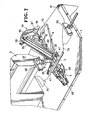
- Fiugre 7 is a fragmentary perspective view of the sewing apparatus, showing a pair of workpiece halves and a concealed slide fastener are set in position at the sewing station.
- Figure 8 is a front elevational view similar to Figure 1, but mainly serves to illustrate how a stacker will function.
- This invention is especially useful for a wide variety of instances of sewing an elongated workpiece or simultaneous elongated workpieces.
- an apparatus application designed for simultaneously sewing a pair of stringers of a concealed slide fastener to a pair of halves of elongated fabric, such as a lady's dress, will be discussed.
- the invention apparatus broadly comprises a table 1, a sewing machine 2 mounted intermediately on the table 1 defining a sewing station 3, a fabric input guide 4 provided forward of the sewing station 3, a fabric strip (eg., slide fastener) guideway 5 provided above the fabric guide 4, a fabric holder 6 provided rearward of and above the sewing station 3, a puller or gripper assembly 7 provided rearward of the sewing station 3 for linear movement, and a sewn fabric stacker 8 provided below the puller 7.
- a table 1 a sewing machine 2 mounted intermediately on the table 1 defining a sewing station 3, a fabric input guide 4 provided forward of the sewing station 3, a fabric strip (eg., slide fastener) guideway 5 provided above the fabric guide 4, a fabric holder 6 provided rearward of and above the sewing station 3, a puller or gripper assembly 7 provided rearward of the sewing station 3 for linear movement, and a sewn fabric stacker 8 provided below the puller 7.
- a fabric input guide 4 provided forward of the sewing station 3
- the construction of the sewing machine 2, itself, does not constitute any part of the invention. Any suitable type of sewing machine may be selected depending on what type of sewing operation will be desired.
- the sewing machine illustrated in this particular embodiment has double needles 9 and suitable foot and dog fabric feed means. Upon depression of a start button, a presser foot 10 descends and the workpiece is lockstitched. Thereafter, the back tack stitch is effected, the thread is broken and finally the presser foot 10 ascends. Since such a sewing machine is of the type commonly put on the market and does not constitute any part of the invention, it is not necessary to go into further detail.
- a vertical thin guidewall or plate 11 stands upwardly from the table 1 and collinear with the imaginary center line of the sewing station 3, as shown in Figures 1, 5 and 6.
- the guide plate 11 is converged toward its rearward end and terminates slightly short of the presser foot 10.
- Astride of the intermediate upper edge of the vertical guide plate 11 is releasably mounted a bracket 12.
- a pair of transparent horizontal guide plates 13 is fixed to the lower surface of the bracket 12 by means of screws 14 (Figure 5) to extend outward from the vertical plate 11.
- a predetermined space is left between the guide plates 13 and the table 1 so as to provide a pair of opposed fabric guide channels 15 ( Figure 5).
- the height of the fabric guide channels 15 can be adjusted by means of a pair of adjustable screws 16 depending on the thickness and the kind of fabric workpiece to be used.
- a pair of guide rods 17 are mounted at the front end of the table 1.
- Each guide rod 17 has one end connected to the corresponding corner of the table 1 via a holder 18 in such a manner that the guide rod 17 is rotatable on a vertical axis.
- the other interior end of each guide rod 17 terminates slightly short of the protruded end of the vertical guide plate 11.
- the rod 17 lies substantially in coplanar relation to the upper surface of the table 1, and is set in inclined relation to the front edge of the table 1, so that a fabric workpiece half is prevented from tending to get diverted toward the vertical guide plate ll where it could thereby get jammed into the fabric guide channel 15.
- An adjustable guide surface 20 lies opposed to a sewing machine body 19 across the sewing station 3 and is adapted for moving toward and away from the sewing station 3.
- the surface 20 is disposed in symmetry with the sewing machine body 19, which serves as an opposed guide surface across the sewing station 3.
- the guide surface 20 functions to keep transportation resistance exerted upon the pair of workpiece halves 75, 76 uniform during movement through the sewing station 3, especially when workpiece halves of great width are sewn, as shown in Figure 7.
- the fabric strip guideway 5 is provided forward of the sewing station 3 and above the input guide 4 and disposed in inclined relation to the upper surface of the table 1.
- the guideway 5 comprises a guide plate 21 having its lead end bifurcated by a rectangular opening 22 so as to provide a pair of projecting branches or legs 23.
- a pair of facing fastener element guides 24 Disposed on the opposed interior lateral sides of the branches 23 are a pair of facing fastener element guides 24.
- Each branch 23 and fastener element guide 24 define therebetween a fastener element guide groove 25 which is open downwardly and slanted here laterally outward for handling a stringer to be used as a concealed stringer in a garment.
- a rectangular leaf spring plate 26 has its one end attached to the lower surface of the guide plate 21 in such a way to cover the rectangular opening 22.
- the lead distal end of the leaf spring is, similarly, bifurcated by a rectangular recess 27 into a pair of separated projecting leaves 28 which leaves cover open bottoms of the fastener element guide grooves 25 respectively.
- the above-mentioned opening 22, recess 27, the interspace interposed between both fastener element guides 24, and the covered end of the vertical guide plate 11 are so physically and cooperatively related to each other as to define a slider guide channel 29.
- the slider being commonly attached to the stringers at a tail end thereof.
- a slider detector 32 comprises a pair of side members 30 and an end member 31 connecting the side members at their ends so as to assume a U-shape.
- the slider detector 32 has its side members 30, 30 pivoted to the side walls of the guide plate 21 with pins 33, so that the slider detector 32 is pivotally mounted on the guide plate 21.
- a cam 34 Provided intermediately of the end member 31 is a cam 34 projecting downwardly.
- the cam 34 is normally positioned within and disposed for movement toward the above-mentioned slider guide channel 29. When the slider passes through the guide channel 29, the slider forces the cam 34 out of the slider guide channel 29, thereby rotating the slider detector 32 clockwise as viewed in Figure 2.
- the guide plate 21 is connected, at its other end, to the bracket 12 via an arm 35, which is pivoted to the bracket 12 by a bolt 36.
- the arrangement is such that the degree to which the fabric strip guideway is inclined relative to the table 1 can be adjusted by simply turning the arm 35 in either direction.
- the relative position of the slide fastener to the sewing station 3 can be adjusted by simply attaching the bracket 12 in variable positions on the vertical guide plate 11.
- the fabric holder 6 is employed for holding in situ each fabric workpiece individually as set by the operator at the sewing station until the sewing operation starts.
- a sewing machine head 37 has a bracket 38 extending rearwardly therefrom.
- a pair of swing arms 39 is rotatably connected to the rear end of the bracket 38 by a pin 40.
- the swing arms 39 extend forwardly to the opposite sides, respectively, of the presser foot 10 at the sewing station 3, and the arms 39 have a pair of holding feet 41, 41 pivoted about lateral axes in the respective distal ends of the arms 39.
- a horizontal plate 42 is integrally connected to the rear end of the bracket 38.
- a pair of screws 43 are screwed on the lower surface of the horizontal plate 42.
- Each of the swing arms 39 has its intermediate portion screwed by a screw 44 as shown in Figure 1.
- a tension spring 45 has one end secured to the screw 44 of the swing arm 39 and the other end to the screw 43 of the horizontal plate 42, in such a manner that, when the arm 39 lies at a depressed position as shown in Figure 1, the spring 45 lies below the pivotal pin 40; while, when the arm 39 lies at an elevated position as shown in Figure 8, the spring 45 lies above the pivotal pin 40. This advantageously ensures that the foot 41 can be retained firmly and stably by the tension of the spring 45, either in the depressed position or in the elevated position.
- An air cylinder 46 is provided on and vertically to the horizontal plate 42.
- a piston rod 47 reciprocally fitted in the air cylinder 46 is provided at its lower end with a horizontal C-shaped plate 48.
- the arrangement is such that, upon retraction of the piston rod 47, the ascending C-shaped plate 48 simultaneously strikes the pair of swing arms 39, thereby causing them to turn anti-clockwise, as viewed in Figure 1, from the depressed position to the elevated position for commencement of sewing operation.
- the gripper assembly 7 is intended to impart a predetermined tension to the workpiece and the slide fastener during the sewing operation to promote and ensure uniform sewing and smooth lines.
- the gripper 7 also quickly withdraws the workpiece and slide fastener already sewn together after the sewing operation is terminated.
- the gripper 7 includes a pair of grippers or fingers 49 for gripping the fabric workpiece and the slide fastener together.
- Each of the grippers 49 comprises a lower holding member 50 positioned slightly above the upper surface of the table 1 and an upper holding member 51 which is rotatably mounted by a pin 53 on a pair of vertical flanges 52 supported on the rear end of the lower holding member 50.
- the upper holding member 51 is connected via a link 54 to the piston rod 57 of the corresponding one of a pair of air cylinders 56, 56.
- a slide 68 is interposed between and connected, at its both sides, to both piston rods 57, 57 of the cylinders 56, 56, respectively.
- a cantilevered pillar 59 stands on the rear end of the table 1.
- a post 60 stands rearwardly of the sewing machine 2.
- the opposed guide rails 61 have their respective inner edges to contoured as to slidably fit in the respective guide grooves 63 formed in the opposite sides of the slide 55.
- a wire 64 is fastened, at its one end, to the front end of the piston (not shown) fitted through the air cylinder 62, passes around a roller 66 provided on the cantilevered post 59 and is fastened, at the other end, to an anchor bracket 68 fixed to the top of the slide 55.
- the other wire 65 is fastened, at its one end, to the rear end of the piston (now shown), passes around a rear roller 67 provided on the top of the pillar 60 and is fastened, at the other end, to the anchor bracket 68 fixed to the top of the slide 55.
- the stacker 8 is provided rearwardly of the sewing machine 2 and below the gripper assembly 7.
- the stacker 8 functions not only to stack finished fabric workpieces having already slide fasteners sewn thereto, but also to withdraw those finished workpieces fully away from the sewing stations and off the table 1 in cooperation with the gripper assembly 7 operation.
- the stacker 8 embodiment here comprises a horizontal pipe 69 and a vertical leg 70 connected, at its top, to the middle of the horizontal pipe 69, so as to form a T-shape.
- a bracket 72 is integrally mounted on a frame 71 so as to extend rearwardly therefrom.
- the vertical leg 70 has its lower end pivotally connected to the rear end of the bracket 72.
- An air cylinder 73 has its bottom pivotally connected to the frame 71 of the table.
- a piston rod 74 reciprocably fitted in the air cylinder 73 has its top pivotally connected to the lower portion of the vertical leg 70. Consequently, stretch of the piston rod 74 through the air cylinder 73 causes the stacker 8 to turn counter-clockwise, as viewed in Figure 1, while retraction of the piston rod 74 causes the stacker 8 to be rotated clockwise back toward the table 1.
- an operator first introduces one workpiece half 75 over the guide rod 17 and along and through the fabric guide 4 into the sewing station 3, properly positions the workpiece half in situ there, and descends the fabric holder 6 thereby making its foot 41 retain the workpiece half 75 to the table 1. Then, the operator sets the other workpiece half on the table 1 in the same manner on the other side of the guide plate 11.
- the leaves of the leaf spring 26 function to maintain the positional stability of the fastener stringers 78 in the guide legs 24.
- a photosensor 80 fixed to the sewing machine 2 detects the lead ends of the slide fastener and workpiece and transmits a control signal so as to actuate the piston rod 57 of the air cylinder 56 to move rightwards, as viewed in Figure 1.
- the gripper 49 grips the superposed ends of the workpiece and the slide fastener and starts to draw them rearwardly from the sewing station 3 applying a predetermined tension less than that applied to the fabric by the sewing machine feed means. Drawing tension can be selected by adjusting the pressure of the air cylinder 62.
- a slider 81 mounted on the slide fastener reaches the slider detector 32.
- the slider causes, via engagement of the cam 34, the slider detector 32 to turn clockwise, as viewed in Figure 7, thereby making its distal end hit a limit switch 82.
- the sewing machine 2 starts to perform the back tack step. Then, after the thread is broken, the presser foot 10 ascends and the sewing machine 2 comes to halt.
- the pressure of the air cylinder 62 is set to be less than the resistance applied to the workpiece and the slide fastener by the feed dog (not shown) and the presser foot 10 of the sewing machine 2, so that the gripper 49 returns in response to performance of the back tack step, comes into a temporary halt during the breakage of the thread, and, after the presser foot 10 ascends, draws the workpiece and the slide fastener rearwardly faster than before.
- the apparatus is now ready for the operator to start another cycle by inputing another slide fastener and another fabric workpiece, both of which are in the form of separate halves.
- the embodiment herein specifically described relates to sewing a pair of stringers for a concealed slide fastener garment to a pair of fabric workpiece halves simultaneously.
- the apparatus be intended for an ordinary slide fastener instead of a concealed slide fastener, the construction of the fabric strip guideway 5 could readily be adapted for the purpose.
- the apparatus be intended for jobs sewing a folded marginal edge of a piece of fabric or sewing together two pieces of fabric along a place where one is superposed on the other, it would not be necessary to provide the apparatus with the guideway 5, and a single fabric guide channel would be satisfactory.
Landscapes
- Engineering & Computer Science (AREA)
- Textile Engineering (AREA)
- Sewing Machines And Sewing (AREA)
Abstract
Description
- This invention relates to automatic sewing of an elongated fabric workpiece, such as a curtain, a tent or a lady's dress, and, in particular, to a method and an apparatus for sewing a slide fastener to elongated fabric pieces.
- It has been often necessary in sewing an elongated fabric workpiece to stitch together folded marginal edges of the fabric piece to prevent unraveling or to sew two pieces of fabric along their marginal edges with one superimposed on the other for joining them. In such known sewing operations, the steps of feeding the fabric workpiece into the sewing station of a sewing machine, positioning it in situ there, and withdrawing it therefrom are performed manually. Since an elongate workpiece is hard to handle, however, it is very difficult to carry out the above-mentioned three steps simultaneously and successively.
- There is a significant drawback in that such sewing operations would require highly experienced dexterity on the part of an operator. Due to the reliance on manual handling during the sewing operation, another drawback is that aesthetically precise and effective sewing could not be expected of such operation.
- When a slide fastener is attached to the opening in an elongated workpiece, such as a tent or a lady's dress; at first, one of the pair of stringers of the slide fastener is superposed on and sewn to one workpiece half defining the opening along its longitudinal edge, and, then, the other stringer is, likewise, superposed on and sewn to the other workpiece half defining the opening along its longitudinal edge. There arise the same drawbacks, and particularly sewing efficiency is very low.
- The present invention seeks to provide a method and apparatus for enabling automatic sewing of elongated fabric workpieces which avoids operator handling during the automatic sewing operation and affords a controlled set up and running of the sewing operation such that precise and efficient sewing reliably results regardless of operator experience or dexterity.
- The present invention further seeks to provide a method and apparatus which enable automatic sewing of a pair of slide fastener stringers simultaneously to both fabric halves defining the opening in such a precise and simple manner that even concealed zipper garments can be produced without wrinkling or unraveling.
- According to a first aspect of the present invention, there is provided apparatus for sewing elongated workpieces comprising a table on which is mounted guide surface means at a front end of said table, a sewing machine disposed intermediate of said table, and a releasable gripper means disposed via drive means for linear back and forth movement between respective forward and rearward stroke positions adjacent said sewing machine and outward away from the rear end of said table, said sewing machine having feed means for conducting a workpiece from said guide surface means, through said sewing machine, and toward said gripper means during operation of said sewing machine, said gripper means engaging a lead end of said workpiece and said drive means drawing said gripper means rearwardly under tension less than that applied to said workpiece by said feed means.
- According to a second aspect of the present invention, there is provided automatic apparatus for sewing a pair of slide fastener stringers to a pair of elongated fabric halves comprising a table on which is mounted an upstanding linearly directed guidewall at a front end of said table, a double-needle sewing machine disposed intermediate of said table having feed means for receiving and conducting said pair of fabric halves from along opposed sides of said guidewall, beneath said sewing machine needles, and toward a rear end of said table, a releasable gripper means disposed via drive means for linear back and forth movement between respective forward and rearward stroke positions adjacent said feed means and outward away from the rear end of said table, said gripper means gripping respective lead ends of said fabric halves simultaneously, an inclined guideway means for conducting a separated pair of slide fastener stringers downward toward said feed means for respective superposed placement onto said pair of fabric halves, and said drive means drawing said gripper means rearward during operation of said sewing machine at a tension less than that applied to the fabric halves by said feed means.
- According to a third aspect of the present invention, there is provided a method for operating an apparatus for automatically sewing elongated workpieces, said apparatus comprising a table on which is mounted a linearly directed, upstanding guidewall at a front end of said table, a sewing machine disposed intermediate of said table, and a releasable gripper means disposed via drive means for linear back and forth movement between respective forward and rearward positions adjacent said sewing machine and outward away from said rear end of said table, said sewing machine having feed means for conducting a workpiece through said sewing machine in a rearward linear direction, said method comprising:
- (a) passing said workpiece along said guidewall such that a leading end thereof engages said feed means,
- (b) clamping said leading end of said workpiece in situ on said feed means,
- (c) operating said sewing machine, including said feed means, while substantially simultaneously removing the clamping of said leading end of said workpiece,
- (d) gripping the leading end of said workpiece as it is conducted rearwardly of said feed means, and
- (e) drawing said gripped workpiece rearwardly away from said table via said drive means with a tension less than that applied to said workpiece by said feed means.
- According to a fourth aspect of the present invention, there is provided a method for sewing a pair of slide fastener stringers to a pair of elongated fabric halves comprising:
- (a) passing a pair of fabric halves separated by an opening to a sewing machine,
- (b) fixably holding adjacent lead ends of said fabric halves on a feed means of said sewing machine,
- (c) providing an inclined guideway ramp for overlying the opening between said fabric halves with a lower end thereof facing onto said feed means,
- (d) opening a pair of slide fastener stringers such that the corded edges thereof face oppositely of one another,
- (e) directing said inverted slide fastener stringers along said guideway ramp such that lead ends of said stringers are superposed on the lead ends of said fabric halves respectively,
- (f) threading said corded edges of said stringers through guide channel means formed on said guideway ramp,
- (g) releasing the hold on said lead ends of said fabric halves and simultaneously commencing operation of said sewing machine, including said feed means.
- Other features and advantages to the present invention will be apparent upon reading of the following detailed description discussion.
- Figure 1 is a front elevational view of a sewing apparatus constructed in accordance with the present invention.
- Figure 2 is a fragmentary perspective view of the sewing apparatus shown in Figure 1.
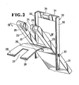
- Figure 3 is a fragmentary perspective view of a slide fastener guideway, with the component parts shown partially separated from each other for better illustration.
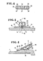
- Figure 4 is a cross-sectional view taken on line IV-IV, of Figure 3, but with the component parts shown closed.
- Figure 5 is a cross-sectional view taken on line V-V of Figure 1.
- Figure 6 is a cross-sectional view taken on line VI-VI of Figure 5.
-
Fiugre 7 is a fragmentary perspective view of the sewing apparatus, showing a pair of workpiece halves and a concealed slide fastener are set in position at the sewing station. - Figure 8 is a front elevational view similar to Figure 1, but mainly serves to illustrate how a stacker will function.
- This invention is especially useful for a wide variety of instances of sewing an elongated workpiece or simultaneous elongated workpieces. For illustration in the drawings and the following description as a preferred embodiment, an apparatus application designed for simultaneously sewing a pair of stringers of a concealed slide fastener to a pair of halves of elongated fabric, such as a lady's dress, will be discussed.
- As shown in Figure 1, the invention apparatus broadly comprises a table 1, a
sewing machine 2 mounted intermediately on the table 1 defining asewing station 3, afabric input guide 4 provided forward of thesewing station 3, a fabric strip (eg., slide fastener)guideway 5 provided above thefabric guide 4, afabric holder 6 provided rearward of and above thesewing station 3, a puller orgripper assembly 7 provided rearward of thesewing station 3 for linear movement, and asewn fabric stacker 8 provided below thepuller 7. - The construction of the
sewing machine 2, itself, does not constitute any part of the invention. Any suitable type of sewing machine may be selected depending on what type of sewing operation will be desired. The sewing machine illustrated in this particular embodiment hasdouble needles 9 and suitable foot and dog fabric feed means. Upon depression of a start button, apresser foot 10 descends and the workpiece is lockstitched. Thereafter, the back tack stitch is effected, the thread is broken and finally thepresser foot 10 ascends. Since such a sewing machine is of the type commonly put on the market and does not constitute any part of the invention, it is not necessary to go into further detail. - In order to guide and desirably align the confronting edges of a pair of opposed fabric workpiece halves, a vertical thin guidewall or
plate 11 stands upwardly from the table 1 and collinear with the imaginary center line of thesewing station 3, as shown in Figures 1, 5 and 6. Theguide plate 11 is converged toward its rearward end and terminates slightly short of thepresser foot 10. Theguide plate 11, at its front end, protrudes beyond the front edge of the table 1 and is directed downwardly off the front edge of the table 1. Astride of the intermediate upper edge of thevertical guide plate 11 is releasably mounted abracket 12. - A pair of transparent
horizontal guide plates 13 is fixed to the lower surface of thebracket 12 by means of screws 14 (Figure 5) to extend outward from thevertical plate 11. A predetermined space is left between theguide plates 13 and the table 1 so as to provide a pair of opposed fabric guide channels 15 (Figure 5). The height of thefabric guide channels 15 can be adjusted by means of a pair ofadjustable screws 16 depending on the thickness and the kind of fabric workpiece to be used. - As shown in Figures 1 and 2, a pair of
guide rods 17 are mounted at the front end of the table 1. Eachguide rod 17 has one end connected to the corresponding corner of the table 1 via aholder 18 in such a manner that theguide rod 17 is rotatable on a vertical axis. The other interior end of eachguide rod 17 terminates slightly short of the protruded end of thevertical guide plate 11. Therod 17 lies substantially in coplanar relation to the upper surface of the table 1, and is set in inclined relation to the front edge of the table 1, so that a fabric workpiece half is prevented from tending to get diverted toward the vertical guide plate ll where it could thereby get jammed into thefabric guide channel 15. - An
adjustable guide surface 20 lies opposed to asewing machine body 19 across thesewing station 3 and is adapted for moving toward and away from thesewing station 3. Thesurface 20 is disposed in symmetry with thesewing machine body 19, which serves as an opposed guide surface across thesewing station 3. Theguide surface 20 functions to keep transportation resistance exerted upon the pair ofworkpiece halves sewing station 3, especially when workpiece halves of great width are sewn, as shown in Figure 7. - As shown in Figures 1 and 2, the
fabric strip guideway 5 is provided forward of thesewing station 3 and above theinput guide 4 and disposed in inclined relation to the upper surface of the table 1. As shown in Figures 2 and 3, theguideway 5 comprises aguide plate 21 having its lead end bifurcated by arectangular opening 22 so as to provide a pair of projecting branches orlegs 23. Disposed on the opposed interior lateral sides of thebranches 23 are a pair of facingfastener element guides 24. Eachbranch 23 andfastener element guide 24 define therebetween a fastenerelement guide groove 25 which is open downwardly and slanted here laterally outward for handling a stringer to be used as a concealed stringer in a garment. - A rectangular
leaf spring plate 26 has its one end attached to the lower surface of theguide plate 21 in such a way to cover therectangular opening 22. The lead distal end of the leaf spring is, similarly, bifurcated by arectangular recess 27 into a pair of separated projectingleaves 28 which leaves cover open bottoms of the fastenerelement guide grooves 25 respectively. As indicated from Figures 2 and 6, the above-mentionedopening 22,recess 27, the interspace interposed between bothfastener element guides 24, and the covered end of thevertical guide plate 11 are so physically and cooperatively related to each other as to define aslider guide channel 29. The slider being commonly attached to the stringers at a tail end thereof. - A
slider detector 32 comprises a pair ofside members 30 and anend member 31 connecting the side members at their ends so as to assume a U-shape. Theslider detector 32 has itsside members guide plate 21 withpins 33, so that theslider detector 32 is pivotally mounted on theguide plate 21. Provided intermediately of theend member 31 is acam 34 projecting downwardly. Thecam 34 is normally positioned within and disposed for movement toward the above-mentionedslider guide channel 29. When the slider passes through theguide channel 29, the slider forces thecam 34 out of theslider guide channel 29, thereby rotating theslider detector 32 clockwise as viewed in Figure 2. - The
guide plate 21 is connected, at its other end, to thebracket 12 via anarm 35, which is pivoted to thebracket 12 by abolt 36. The arrangement is such that the degree to which the fabric strip guideway is inclined relative to the table 1 can be adjusted by simply turning thearm 35 in either direction. - The relative position of the slide fastener to the
sewing station 3 can be adjusted by simply attaching thebracket 12 in variable positions on thevertical guide plate 11. - The
fabric holder 6 is employed for holding in situ each fabric workpiece individually as set by the operator at the sewing station until the sewing operation starts. As will be apparent from Figures 1 and 2, asewing machine head 37 has abracket 38 extending rearwardly therefrom. A pair ofswing arms 39 is rotatably connected to the rear end of thebracket 38 by apin 40. Theswing arms 39 extend forwardly to the opposite sides, respectively, of thepresser foot 10 at thesewing station 3, and thearms 39 have a pair of holdingfeet arms 39. - A
horizontal plate 42 is integrally connected to the rear end of thebracket 38. A pair ofscrews 43 are screwed on the lower surface of thehorizontal plate 42. Each of theswing arms 39 has its intermediate portion screwed by ascrew 44 as shown in Figure 1. Atension spring 45 has one end secured to thescrew 44 of theswing arm 39 and the other end to thescrew 43 of thehorizontal plate 42, in such a manner that, when thearm 39 lies at a depressed position as shown in Figure 1, thespring 45 lies below thepivotal pin 40; while, when thearm 39 lies at an elevated position as shown in Figure 8, thespring 45 lies above thepivotal pin 40. This advantageously ensures that thefoot 41 can be retained firmly and stably by the tension of thespring 45, either in the depressed position or in the elevated position. - An
air cylinder 46 is provided on and vertically to thehorizontal plate 42. Apiston rod 47 reciprocally fitted in theair cylinder 46 is provided at its lower end with a horizontal C-shapedplate 48. The arrangement is such that, upon retraction of thepiston rod 47, the ascending C-shapedplate 48 simultaneously strikes the pair ofswing arms 39, thereby causing them to turn anti-clockwise, as viewed in Figure 1, from the depressed position to the elevated position for commencement of sewing operation. - The
gripper assembly 7 is intended to impart a predetermined tension to the workpiece and the slide fastener during the sewing operation to promote and ensure uniform sewing and smooth lines. Thegripper 7 also quickly withdraws the workpiece and slide fastener already sewn together after the sewing operation is terminated. - As shown in Figures 1 and 2, the
gripper 7 includes a pair of grippers orfingers 49 for gripping the fabric workpiece and the slide fastener together. Each of thegrippers 49 comprises alower holding member 50 positioned slightly above the upper surface of the table 1 and an upper holdingmember 51 which is rotatably mounted by apin 53 on a pair ofvertical flanges 52 supported on the rear end of the lower holdingmember 50. Besides, the upper holdingmember 51 is connected via alink 54 to thepiston rod 57 of the corresponding one of a pair ofair cylinders slide 68 is interposed between and connected, at its both sides, to bothpiston rods cylinders piston rod 57 will cause thegripper 49 to close, while retraction ofpiston rod 57 will cause thegripper 49 to open. Thelower holding member 50 is connected to aslide 55 via aconnector 58 so that thegripper 49 will move together with theslide 55. - A cantilevered
pillar 59 stands on the rear end of the table 1. Apost 60 stands rearwardly of thesewing machine 2. Provided between the distal end of the cantileveredpillar 59 and the upper end of thepost 60 are a pair ofguide rails slide 55 therebetween and anair cylinder 62 for reciprocating theslide 55 along the guide rails 61. Theopposed guide rails 61 have their respective inner edges to contoured as to slidably fit in therespective guide grooves 63 formed in the opposite sides of theslide 55. Awire 64 is fastened, at its one end, to the front end of the piston (not shown) fitted through theair cylinder 62, passes around aroller 66 provided on the cantileveredpost 59 and is fastened, at the other end, to ananchor bracket 68 fixed to the top of theslide 55. Theother wire 65 is fastened, at its one end, to the rear end of the piston (now shown), passes around arear roller 67 provided on the top of thepillar 60 and is fastened, at the other end, to theanchor bracket 68 fixed to the top of theslide 55. Consequently, when the piston moves through theair cylinder 62 rightwards, as viewed in Figure 1, this causes theslide 55 and hence thegripper 49 to move outwardly rearward from thesewing station 3, while the piston's moving leftwards causes thegripper 49 to move forwardly towards thesewing station 3. - As shown in Figure 1, the
stacker 8 is provided rearwardly of thesewing machine 2 and below thegripper assembly 7. Thestacker 8 functions not only to stack finished fabric workpieces having already slide fasteners sewn thereto, but also to withdraw those finished workpieces fully away from the sewing stations and off the table 1 in cooperation with thegripper assembly 7 operation. - The
stacker 8 embodiment here comprises ahorizontal pipe 69 and avertical leg 70 connected, at its top, to the middle of thehorizontal pipe 69, so as to form a T-shape. Abracket 72 is integrally mounted on aframe 71 so as to extend rearwardly therefrom. Thevertical leg 70 has its lower end pivotally connected to the rear end of thebracket 72. Anair cylinder 73 has its bottom pivotally connected to theframe 71 of the table. Apiston rod 74 reciprocably fitted in theair cylinder 73 has its top pivotally connected to the lower portion of thevertical leg 70. Consequently, stretch of thepiston rod 74 through theair cylinder 73 causes thestacker 8 to turn counter-clockwise, as viewed in Figure 1, while retraction of thepiston rod 74 causes thestacker 8 to be rotated clockwise back toward the table 1. - Operation of the invention apparatus and method will now be described.
- As shown in Figure 7, before starting the sewing operation, an operator first introduces one
workpiece half 75 over theguide rod 17 and along and through thefabric guide 4 into thesewing station 3, properly positions the workpiece half in situ there, and descends thefabric holder 6 thereby making itsfoot 41 retain theworkpiece half 75 to the table 1. Then, the operator sets the other workpiece half on the table 1 in the same manner on the other side of theguide plate 11. - The operator then opens the
slide fastener 77, places thefastener stringers fabric strip guideway 5 in an inverted disposition (to permit concealment when reversed back in the finished garment) as shown in Figure 7, introduces the leading ends of the stringers through between thefastener element guide 24 and theleaf spring 26 into thesewing station 3, and superposes the leading ends of the stringers onto the already set workpiece halves. The corded ortoothed edges 79 of thestringers 78 fit through the fastenerelement guide grooves 25 respectively, of thefastener element guide 24. The leaves of theleaf spring 26 function to maintain the positional stability of thefastener stringers 78 in theguide legs 24. - Upon depression of a start button (not shown), the
presser foot 10 and theneedles 9 descend, and the sewing operation starts. At the almost same time, thepiston rod 47 of theair cylinder 46 reciprocates, so that the C-shapedhorizontal plate 48 causes swingarms spring 45, thereby lifting theholder feet 41 from the workpiece halves. - As the sewing operation proceeds, the leading ends of the fabric workpiece and slide fastener come into the space between the upper and lower holding
members gripper 49. At this time, a photosensor 80 (see Figure 1) fixed to thesewing machine 2 detects the lead ends of the slide fastener and workpiece and transmits a control signal so as to actuate thepiston rod 57 of theair cylinder 56 to move rightwards, as viewed in Figure 1. Thereby, thegripper 49 grips the superposed ends of the workpiece and the slide fastener and starts to draw them rearwardly from thesewing station 3 applying a predetermined tension less than that applied to the fabric by the sewing machine feed means. Drawing tension can be selected by adjusting the pressure of theair cylinder 62. - As the sewing operation proceeds, a
slider 81 mounted on the slide fastener reaches theslider detector 32. Here, the slider causes, via engagement of thecam 34, theslider detector 32 to turn clockwise, as viewed in Figure 7, thereby making its distal end hit alimit switch 82. With a signal transmitted by thelimit switch 82, thesewing machine 2 starts to perform the back tack step. Then, after the thread is broken, thepresser foot 10 ascends and thesewing machine 2 comes to halt. - It is to be especially noted that the pressure of the
air cylinder 62 is set to be less than the resistance applied to the workpiece and the slide fastener by the feed dog (not shown) and thepresser foot 10 of thesewing machine 2, so that thegripper 49 returns in response to performance of the back tack step, comes into a temporary halt during the breakage of the thread, and, after thepresser foot 10 ascends, draws the workpiece and the slide fastener rearwardly faster than before. - When the
slide 55 hits alimit switch 83, thepiston rod 57 of theair cylinder 56 retracts, thereby spreading the holdingmembers gripper 49, so that the workpiece and the slide fastener drop onto thehorizontal pipe 69 of thestacker 8, as shown by an imaginary line in Figure 1. - When the
slide 55 hits alimit switch 84, the piston rod of theair cylinder 62 moves leftwards, as viewed in Figure 1, and thepiston rod 74 of theair cylinder 73 stretches. Consequently, thegripper 49 starts to be restored toward thesewing station 3, and thestacker 8 turns anti-clockwise, as viewed in Figure 1, thereby positively withdrawing the tail end of the workpiece which, otherwise, might remain on the table therefrom. - When the
slide 55 hits alimit switch 85, the supply of air to theair cylinder 62 comes to a halt, and thepiston rod 74 of theair cylinder 73 retracts. Consequently, theslide 55 keeps moving to some extent under inertia and finally comes into abutment against suitable stop (not shown) to the forward stroke position, whereby thegripper 49 is restored to its original open or receiving position and, likewise, the stacker is restored to the original position. - The apparatus is now ready for the operator to start another cycle by inputing another slide fastener and another fabric workpiece, both of which are in the form of separate halves.
- The embodiment herein specifically described relates to sewing a pair of stringers for a concealed slide fastener garment to a pair of fabric workpiece halves simultaneously. Should the apparatus be intended for an ordinary slide fastener instead of a concealed slide fastener, the construction of the
fabric strip guideway 5 could readily be adapted for the purpose. Should the apparatus be intended for jobs sewing a folded marginal edge of a piece of fabric or sewing together two pieces of fabric along a place where one is superposed on the other, it would not be necessary to provide the apparatus with theguideway 5, and a single fabric guide channel would be satisfactory.
Claims (22)
Applications Claiming Priority (2)
| Application Number | Priority Date | Filing Date | Title |
|---|---|---|---|
| US535729 | 1983-09-26 | ||
| US06/535,729 US4497270A (en) | 1983-09-26 | 1983-09-26 | Method and apparatus for sewing elongated fabric piece |
Publications (3)
| Publication Number | Publication Date |
|---|---|
| EP0141252A2 true EP0141252A2 (en) | 1985-05-15 |
| EP0141252A3 EP0141252A3 (en) | 1985-06-12 |
| EP0141252B1 EP0141252B1 (en) | 1988-05-11 |
Family
ID=24135525
Family Applications (1)
| Application Number | Title | Priority Date | Filing Date |
|---|---|---|---|
| EP84111481A Expired EP0141252B1 (en) | 1983-09-26 | 1984-09-26 | Method amd apparatus for sewing elongated fabrik piece |
Country Status (15)
| Country | Link |
|---|---|
| US (1) | US4497270A (en) |
| EP (1) | EP0141252B1 (en) |
| JP (1) | JPS6090593A (en) |
| KR (1) | KR870001272B1 (en) |
| AU (1) | AU553317B2 (en) |
| BR (1) | BR8404903A (en) |
| CA (1) | CA1227701A (en) |
| DE (1) | DE3471119D1 (en) |
| ES (3) | ES536235A0 (en) |
| FI (1) | FI843738L (en) |
| GB (2) | GB2147623B (en) |
| HK (2) | HK40789A (en) |
| MY (2) | MY100550A (en) |
| SG (1) | SG18889G (en) |
| ZA (1) | ZA847061B (en) |
Cited By (1)
| Publication number | Priority date | Publication date | Assignee | Title |
|---|---|---|---|---|
| US9461930B2 (en) | 2009-04-27 | 2016-10-04 | Intel Corporation | Modifying data streams without reordering in a multi-thread, multi-flow network processor |
Families Citing this family (21)
| Publication number | Priority date | Publication date | Assignee | Title |
|---|---|---|---|---|
| US4541352A (en) * | 1983-06-08 | 1985-09-17 | Yoshida Kogyo K. K. | Method of and apparatus for attaching fly strips to a slide fastener chain |
| GB2155512B (en) * | 1984-03-06 | 1987-01-14 | Yoshida Kogyo Kk | Device for guiding concealed slide fastener stringers to a sewing machine |
| DE8416290U1 (en) * | 1984-05-26 | 1984-08-30 | Dürkoppwerke GmbH, 4800 Bielefeld | SEWING MACHINE FOR MAKING POCKETS |
| US4644886A (en) * | 1984-08-23 | 1987-02-24 | Yoshida Kogyo K. K. | Method and apparatus for attaching fly strips to a slide fastener chain |
| US4593635A (en) * | 1985-03-06 | 1986-06-10 | Yoshida Kogyo K. K. | Method and apparatus for sewing a slide fastener to fabric pieces |
| JPS61203903A (en) * | 1985-03-08 | 1986-09-09 | ワイケイケイ株式会社 | Method and apparatus for stitching slide fastener |
| JPS61206403A (en) * | 1985-03-08 | 1986-09-12 | ワイケイケイ株式会社 | Slider sliding apparatus in stitching machine for slide fastener |
| US4674422A (en) * | 1986-08-07 | 1987-06-23 | Yoshida Kogyo K. K. | Apparatus for sewing zipper chain to elongated fabric pieces |
| US4714038A (en) * | 1986-08-07 | 1987-12-22 | Yoshida Kogyo K. K. | Method for sewing zipper chain to elongated fabric pieces |
| JPS63119796A (en) * | 1986-11-08 | 1988-05-24 | ジューキ株式会社 | Cloth setting device for skirt fastener fitting sewing machine |
| JPH0714364B2 (en) * | 1987-06-30 | 1995-02-22 | ワイケイケイ株式会社 | Method and apparatus for supplying and sewing protective tape to end of slide fastener |
| JPS6462191A (en) * | 1987-08-31 | 1989-03-08 | Juki Kk | Cloth setting device in fastner sewing machine |
| JPH0630806Y2 (en) * | 1988-07-11 | 1994-08-17 | サンビーム工業株式会社 | Auxiliary material for zipper installation |
| US4956879A (en) * | 1989-04-18 | 1990-09-18 | Meltzer Industries Corporation | Garment having seamless body |
| US5237705A (en) * | 1992-04-14 | 1993-08-24 | Obion Denton Co. | Method of making a garment having a seamless body portion |
| JP2578155Y2 (en) * | 1992-11-16 | 1998-08-06 | 織田寝装株式会社 | Fastener sewing device for cover fabric |
| US5959233A (en) * | 1997-09-12 | 1999-09-28 | The United States Of America As Represented By The Secretary Of The Navy | Line charge fastener and detonating cord guide |
| WO2011077534A1 (en) * | 2009-12-24 | 2011-06-30 | Ykk株式会社 | Method for sewing fastener stringer, method for manufacturing product to which fastener is attached, product to which faster is attached, and sewing machine foot |
| US9032888B2 (en) * | 2011-11-30 | 2015-05-19 | Irvin Automotive Products, Inc. | Bus seat back trim and method and apparatus for making |
| CN104746248A (en) * | 2013-12-30 | 2015-07-01 | 波司登羽绒服装有限公司 | Presser foot of bartack sewing machine and using method of presser foot |
| CN105696215A (en) * | 2014-11-27 | 2016-06-22 | 安徽太平洋特种网业有限公司 | A papermaking drying mesh zipper sewing machine |
Citations (8)
| Publication number | Priority date | Publication date | Assignee | Title |
|---|---|---|---|---|
| US2329991A (en) * | 1940-05-23 | 1943-09-21 | Crown Fastener Corp | Apparatus for attaching separable fasteners |
| FR1404026A (en) * | 1964-06-30 | 1965-06-25 | Chveinaia Fabrika No 9 Upravle | Semi-automatic sewing machine |
| FR2076478A5 (en) * | 1969-01-10 | 1971-10-15 | Opti Holding Ag | |
| FR2217965A5 (en) * | 1973-02-13 | 1974-09-06 | Normande Confection | Stacker-folder for stitched articles - esp. long workpieces leaving a sewing machine worktable |
| US3893402A (en) * | 1973-10-02 | 1975-07-08 | B & W Manufacturing Co | Sewing apparatus |
| FR2326521A1 (en) * | 1975-10-03 | 1977-04-29 | Rockwell Rimoldi Spa | SET FOR AUTOMATIC SEWING OF OPPOSING EDGES OF A FABRIC |
| DE2607235A1 (en) * | 1976-02-23 | 1977-08-25 | Duerkoppwerke | GUIDE DEVICE FOR FLEXIBLE WORK PIECES |
| US4217840A (en) * | 1978-04-10 | 1980-08-19 | The United States Bedding Company | Zipper sewing attachment and method |
Family Cites Families (8)
| Publication number | Priority date | Publication date | Assignee | Title |
|---|---|---|---|---|
| US2862467A (en) * | 1954-05-03 | 1958-12-02 | Joseph Machine Co Inc | Belt making machine |
| US3381639A (en) * | 1966-02-21 | 1968-05-07 | Quick Service Textiles | Apparatus for feeding and cutting strip material |
| US3675604A (en) * | 1970-10-08 | 1972-07-11 | Oxford Industries | Garment cutting and stacking method |
| US3741652A (en) * | 1972-02-16 | 1973-06-26 | Eastman Kodak Co | Method for producing plates having enlarged halftone patterns and article produced by said process |
| JPS5071442A (en) * | 1973-10-27 | 1975-06-13 | ||
| US4111137A (en) * | 1976-10-01 | 1978-09-05 | Hampton Industries, Inc. | Cuff making machine |
| US4343255A (en) * | 1979-05-01 | 1982-08-10 | Starkville Tool And Die Company | Automated placket shirt machine |
| US4274347A (en) * | 1980-08-18 | 1981-06-23 | Textron, Inc. | Apparatus for sewing slide fastener chain to article panels |
-
1983
- 1983-09-26 US US06/535,729 patent/US4497270A/en not_active Expired - Fee Related
-
1984
- 1984-09-07 GB GB08422636A patent/GB2147623B/en not_active Expired
- 1984-09-07 ZA ZA847061A patent/ZA847061B/en unknown
- 1984-09-13 CA CA000463091A patent/CA1227701A/en not_active Expired
- 1984-09-19 AU AU33279/84A patent/AU553317B2/en not_active Ceased
- 1984-09-22 JP JP59199317A patent/JPS6090593A/en active Granted
- 1984-09-24 FI FI843738A patent/FI843738L/en not_active Application Discontinuation
- 1984-09-25 KR KR1019840005866A patent/KR870001272B1/en not_active IP Right Cessation
- 1984-09-26 DE DE8484111481T patent/DE3471119D1/en not_active Expired
- 1984-09-26 EP EP84111481A patent/EP0141252B1/en not_active Expired
- 1984-09-26 ES ES536235A patent/ES536235A0/en active Granted
- 1984-09-26 ES ES536234A patent/ES536234A0/en active Granted
- 1984-09-26 BR BR8404903A patent/BR8404903A/en not_active IP Right Cessation
- 1984-09-26 ES ES536233A patent/ES8507200A1/en not_active Expired
-
1986
- 1986-05-30 GB GB08613147A patent/GB2175023B/en not_active Expired
-
1987
- 1987-08-11 MY MYPI87001282A patent/MY100550A/en unknown
- 1987-08-12 MY MYPI87001312A patent/MY100356A/en unknown
-
1989
- 1989-03-30 SG SG188/89A patent/SG18889G/en unknown
- 1989-05-18 HK HK407/89A patent/HK40789A/en unknown
- 1989-05-18 HK HK406/89A patent/HK40689A/en unknown
Patent Citations (8)
| Publication number | Priority date | Publication date | Assignee | Title |
|---|---|---|---|---|
| US2329991A (en) * | 1940-05-23 | 1943-09-21 | Crown Fastener Corp | Apparatus for attaching separable fasteners |
| FR1404026A (en) * | 1964-06-30 | 1965-06-25 | Chveinaia Fabrika No 9 Upravle | Semi-automatic sewing machine |
| FR2076478A5 (en) * | 1969-01-10 | 1971-10-15 | Opti Holding Ag | |
| FR2217965A5 (en) * | 1973-02-13 | 1974-09-06 | Normande Confection | Stacker-folder for stitched articles - esp. long workpieces leaving a sewing machine worktable |
| US3893402A (en) * | 1973-10-02 | 1975-07-08 | B & W Manufacturing Co | Sewing apparatus |
| FR2326521A1 (en) * | 1975-10-03 | 1977-04-29 | Rockwell Rimoldi Spa | SET FOR AUTOMATIC SEWING OF OPPOSING EDGES OF A FABRIC |
| DE2607235A1 (en) * | 1976-02-23 | 1977-08-25 | Duerkoppwerke | GUIDE DEVICE FOR FLEXIBLE WORK PIECES |
| US4217840A (en) * | 1978-04-10 | 1980-08-19 | The United States Bedding Company | Zipper sewing attachment and method |
Cited By (1)
| Publication number | Priority date | Publication date | Assignee | Title |
|---|---|---|---|---|
| US9461930B2 (en) | 2009-04-27 | 2016-10-04 | Intel Corporation | Modifying data streams without reordering in a multi-thread, multi-flow network processor |
Also Published As
| Publication number | Publication date |
|---|---|
| HK40789A (en) | 1989-05-26 |
| JPS6090593A (en) | 1985-05-21 |
| EP0141252B1 (en) | 1988-05-11 |
| EP0141252A3 (en) | 1985-06-12 |
| GB2147623A (en) | 1985-05-15 |
| CA1227701A (en) | 1987-10-06 |
| ES536233A0 (en) | 1985-09-01 |
| GB2175023A (en) | 1986-11-19 |
| US4497270A (en) | 1985-02-05 |
| MY100550A (en) | 1990-11-15 |
| JPS6351038B2 (en) | 1988-10-12 |
| ES8506991A1 (en) | 1985-07-16 |
| HK40689A (en) | 1989-05-26 |
| AU553317B2 (en) | 1986-07-10 |
| ES8507201A1 (en) | 1985-09-01 |
| FI843738L (en) | 1985-03-27 |
| ES536234A0 (en) | 1985-09-01 |
| KR870001272B1 (en) | 1987-06-30 |
| DE3471119D1 (en) | 1988-06-16 |
| BR8404903A (en) | 1985-08-20 |
| MY100356A (en) | 1990-08-28 |
| GB8613147D0 (en) | 1986-07-02 |
| ES8507200A1 (en) | 1985-09-01 |
| KR850002498A (en) | 1985-05-13 |
| ES536235A0 (en) | 1985-07-16 |
| GB2175023B (en) | 1987-07-01 |
| GB2147623B (en) | 1987-07-01 |
| AU3327984A (en) | 1985-04-04 |
| FI843738A0 (en) | 1984-09-24 |
| ZA847061B (en) | 1985-04-24 |
| GB8422636D0 (en) | 1984-10-10 |
| SG18889G (en) | 1989-07-07 |
Similar Documents
| Publication | Publication Date | Title |
|---|---|---|
| US4497270A (en) | Method and apparatus for sewing elongated fabric piece | |
| CN109440310B (en) | Automatic rib knitting machine | |
| US4541352A (en) | Method of and apparatus for attaching fly strips to a slide fastener chain | |
| US4800830A (en) | Hemmer seamer assembly | |
| US4660821A (en) | Method of and apparatus for attaching fly strips to a slide fastener chain | |
| CA1260768A (en) | Mechanism for drawing an elongated sewn product from a sewing machine | |
| JPH0312909B2 (en) | ||
| CN109457406B (en) | Rolling device of automatic rib knitting machine | |
| US4674422A (en) | Apparatus for sewing zipper chain to elongated fabric pieces | |
| US4104977A (en) | Fabric-feed control for sewing machine | |
| US4714038A (en) | Method for sewing zipper chain to elongated fabric pieces | |
| JP2641080B2 (en) | Edge sewing machine for trousers | |
| JPH0435195B2 (en) | ||
| CN109505075B (en) | Feeding mechanism of automatic rib knitting machine | |
| US4951586A (en) | Sewing machine attachment for aligning a reinforcement member in a hem | |
| JPH0642621Y2 (en) | Sewing machine bundle-slackening device | |
| US4632045A (en) | Slider-moving unit in apparatus for sewing a slide fastener to a pair of fabric pieces | |
| CA1253398A (en) | Method and apparatus for sewing a slide fastener to fabric pieces | |
| US4878445A (en) | Hemmer seamer assembly | |
| JPH0382498A (en) | Automatic head distance control device for cuff sewing device | |
| JP2529499Y2 (en) | Fastener sewing device for tubular fabric | |
| JPH0698240B2 (en) | Cloth opening device | |
| GB2172017A (en) | Method and apparatus for sewing a slide fastener to fabric pieces |
Legal Events
| Date | Code | Title | Description |
|---|---|---|---|
| PUAI | Public reference made under article 153(3) epc to a published international application that has entered the european phase |
Free format text: ORIGINAL CODE: 0009012 |
|
| PUAL | Search report despatched |
Free format text: ORIGINAL CODE: 0009013 |
|
| AK | Designated contracting states |
Designated state(s): BE CH DE FR IT LI NL SE |
|
| AK | Designated contracting states |
Designated state(s): BE CH DE FR IT LI NL SE |
|
| 17P | Request for examination filed |
Effective date: 19850814 |
|
| 17Q | First examination report despatched |
Effective date: 19860801 |
|
| R17C | First examination report despatched (corrected) |
Effective date: 19870210 |
|
| GRAA | (expected) grant |
Free format text: ORIGINAL CODE: 0009210 |
|
| AK | Designated contracting states |
Kind code of ref document: B1 Designated state(s): BE CH DE FR IT LI NL SE |
|
| ITF | It: translation for a ep patent filed |
Owner name: JACOBACCI & PERANI S.P.A. |
|
| REF | Corresponds to: |
Ref document number: 3471119 Country of ref document: DE Date of ref document: 19880616 |
|
| ET | Fr: translation filed | ||
| PLBE | No opposition filed within time limit |
Free format text: ORIGINAL CODE: 0009261 |
|
| STAA | Information on the status of an ep patent application or granted ep patent |
Free format text: STATUS: NO OPPOSITION FILED WITHIN TIME LIMIT |
|
| 26N | No opposition filed | ||
| ITTA | It: last paid annual fee | ||
| PGFP | Annual fee paid to national office [announced via postgrant information from national office to epo] |
Ref country code: SE Payment date: 19940608 Year of fee payment: 11 |
|
| PGFP | Annual fee paid to national office [announced via postgrant information from national office to epo] |
Ref country code: BE Payment date: 19940621 Year of fee payment: 11 |
|
| PGFP | Annual fee paid to national office [announced via postgrant information from national office to epo] |
Ref country code: FR Payment date: 19940818 Year of fee payment: 11 |
|
| PGFP | Annual fee paid to national office [announced via postgrant information from national office to epo] |
Ref country code: CH Payment date: 19940906 Year of fee payment: 11 |
|
| PGFP | Annual fee paid to national office [announced via postgrant information from national office to epo] |
Ref country code: DE Payment date: 19940929 Year of fee payment: 11 |
|
| PGFP | Annual fee paid to national office [announced via postgrant information from national office to epo] |
Ref country code: NL Payment date: 19940930 Year of fee payment: 11 |
|
| REG | Reference to a national code |
Ref country code: CH Ref legal event code: PFA Free format text: YKK CORPORATION |
|
| ITPR | It: changes in ownership of a european patent |
Owner name: CAMBIO RAGIONE SOCIALE;YKK CORPORATION |
|
| REG | Reference to a national code |
Ref country code: FR Ref legal event code: CD |
|
| EAL | Se: european patent in force in sweden |
Ref document number: 84111481.2 |
|
| NLT1 | Nl: modifications of names registered in virtue of documents presented to the patent office pursuant to art. 16 a, paragraph 1 |
Owner name: YKK CORPORATION TE TOKIO, JAPAN. |
|
| PG25 | Lapsed in a contracting state [announced via postgrant information from national office to epo] |
Ref country code: SE Effective date: 19950927 |
|
| PG25 | Lapsed in a contracting state [announced via postgrant information from national office to epo] |
Ref country code: LI Effective date: 19950930 Ref country code: CH Effective date: 19950930 Ref country code: BE Effective date: 19950930 |
|
| BERE | Be: lapsed |
Owner name: YKK CORP. Effective date: 19950930 |
|
| PG25 | Lapsed in a contracting state [announced via postgrant information from national office to epo] |
Ref country code: NL Effective date: 19960401 |
|
| REG | Reference to a national code |
Ref country code: CH Ref legal event code: PL |
|
| PG25 | Lapsed in a contracting state [announced via postgrant information from national office to epo] |
Ref country code: FR Effective date: 19960531 |
|
| PG25 | Lapsed in a contracting state [announced via postgrant information from national office to epo] |
Ref country code: DE Effective date: 19960601 |
|
| NLV4 | Nl: lapsed or anulled due to non-payment of the annual fee |
Effective date: 19960401 |
|
| EUG | Se: european patent has lapsed |
Ref document number: 84111481.2 |
|
| REG | Reference to a national code |
Ref country code: FR Ref legal event code: ST |