EP0140785A1 - Wickler mit gesteuerter Zusammenpressung - Google Patents
Wickler mit gesteuerter Zusammenpressung Download PDFInfo
- Publication number
- EP0140785A1 EP0140785A1 EP84402107A EP84402107A EP0140785A1 EP 0140785 A1 EP0140785 A1 EP 0140785A1 EP 84402107 A EP84402107 A EP 84402107A EP 84402107 A EP84402107 A EP 84402107A EP 0140785 A1 EP0140785 A1 EP 0140785A1
- Authority
- EP
- European Patent Office
- Prior art keywords
- felt
- arm
- winding
- strip
- roller
- Prior art date
- Legal status (The legal status is an assumption and is not a legal conclusion. Google has not performed a legal analysis and makes no representation as to the accuracy of the status listed.)
- Granted
Links
- 238000007906 compression Methods 0.000 title claims abstract description 52
- 230000006835 compression Effects 0.000 title claims abstract description 51
- 238000004804 winding Methods 0.000 claims abstract description 39
- 238000000034 method Methods 0.000 claims abstract description 18
- 230000015572 biosynthetic process Effects 0.000 claims abstract description 9
- 239000000463 material Substances 0.000 claims abstract description 5
- 230000033001 locomotion Effects 0.000 claims description 21
- 238000004364 calculation method Methods 0.000 claims description 19
- 238000006073 displacement reaction Methods 0.000 claims description 9
- 230000006870 function Effects 0.000 claims description 8
- 238000005259 measurement Methods 0.000 claims description 6
- 230000003247 decreasing effect Effects 0.000 claims description 2
- 230000001154 acute effect Effects 0.000 claims 1
- 238000001514 detection method Methods 0.000 claims 1
- 239000011490 mineral wool Substances 0.000 abstract description 2
- 239000000835 fiber Substances 0.000 description 8
- 238000012360 testing method Methods 0.000 description 6
- 238000004806 packaging method and process Methods 0.000 description 5
- 238000011084 recovery Methods 0.000 description 5
- 239000011230 binding agent Substances 0.000 description 4
- 238000006243 chemical reaction Methods 0.000 description 4
- 230000003750 conditioning effect Effects 0.000 description 4
- 238000010586 diagram Methods 0.000 description 4
- 230000014509 gene expression Effects 0.000 description 4
- 230000005540 biological transmission Effects 0.000 description 3
- 238000000576 coating method Methods 0.000 description 3
- 238000004519 manufacturing process Methods 0.000 description 3
- 230000007547 defect Effects 0.000 description 2
- 230000000694 effects Effects 0.000 description 2
- 238000009434 installation Methods 0.000 description 2
- 230000007246 mechanism Effects 0.000 description 2
- 230000004048 modification Effects 0.000 description 2
- 238000012986 modification Methods 0.000 description 2
- 239000000123 paper Substances 0.000 description 2
- 239000002861 polymer material Substances 0.000 description 2
- 230000008569 process Effects 0.000 description 2
- 238000012545 processing Methods 0.000 description 2
- 238000003860 storage Methods 0.000 description 2
- 241001080024 Telles Species 0.000 description 1
- 238000004026 adhesive bonding Methods 0.000 description 1
- 238000005452 bending Methods 0.000 description 1
- 238000005119 centrifugation Methods 0.000 description 1
- 230000008859 change Effects 0.000 description 1
- 239000011248 coating agent Substances 0.000 description 1
- 238000012937 correction Methods 0.000 description 1
- 239000003365 glass fiber Substances 0.000 description 1
- 239000011491 glass wool Substances 0.000 description 1
- 230000000977 initiatory effect Effects 0.000 description 1
- 229910052500 inorganic mineral Inorganic materials 0.000 description 1
- 239000002655 kraft paper Substances 0.000 description 1
- 238000012423 maintenance Methods 0.000 description 1
- 239000011707 mineral Substances 0.000 description 1
- 239000012768 molten material Substances 0.000 description 1
- 238000011022 operating instruction Methods 0.000 description 1
- 229920000642 polymer Polymers 0.000 description 1
- 238000006116 polymerization reaction Methods 0.000 description 1
- 238000002360 preparation method Methods 0.000 description 1
- 230000009467 reduction Effects 0.000 description 1
- 230000004044 response Effects 0.000 description 1
- 239000011435 rock Substances 0.000 description 1
- 238000005096 rolling process Methods 0.000 description 1
Images
Classifications
-
- B—PERFORMING OPERATIONS; TRANSPORTING
- B65—CONVEYING; PACKING; STORING; HANDLING THIN OR FILAMENTARY MATERIAL
- B65H—HANDLING THIN OR FILAMENTARY MATERIAL, e.g. SHEETS, WEBS, CABLES
- B65H43/00—Use of control, checking, or safety devices, e.g. automatic devices comprising an element for sensing a variable
-
- B—PERFORMING OPERATIONS; TRANSPORTING
- B65—CONVEYING; PACKING; STORING; HANDLING THIN OR FILAMENTARY MATERIAL
- B65H—HANDLING THIN OR FILAMENTARY MATERIAL, e.g. SHEETS, WEBS, CABLES
- B65H18/00—Winding webs
- B65H18/08—Web-winding mechanisms
- B65H18/14—Mechanisms in which power is applied to web roll, e.g. to effect continuous advancement of web
- B65H18/16—Mechanisms in which power is applied to web roll, e.g. to effect continuous advancement of web by friction roller
-
- B—PERFORMING OPERATIONS; TRANSPORTING
- B65—CONVEYING; PACKING; STORING; HANDLING THIN OR FILAMENTARY MATERIAL
- B65H—HANDLING THIN OR FILAMENTARY MATERIAL, e.g. SHEETS, WEBS, CABLES
- B65H18/00—Winding webs
-
- B—PERFORMING OPERATIONS; TRANSPORTING
- B65—CONVEYING; PACKING; STORING; HANDLING THIN OR FILAMENTARY MATERIAL
- B65H—HANDLING THIN OR FILAMENTARY MATERIAL, e.g. SHEETS, WEBS, CABLES
- B65H18/00—Winding webs
- B65H18/08—Web-winding mechanisms
- B65H18/14—Mechanisms in which power is applied to web roll, e.g. to effect continuous advancement of web
- B65H18/22—Mechanisms in which power is applied to web roll, e.g. to effect continuous advancement of web by friction band
-
- B—PERFORMING OPERATIONS; TRANSPORTING
- B65—CONVEYING; PACKING; STORING; HANDLING THIN OR FILAMENTARY MATERIAL
- B65H—HANDLING THIN OR FILAMENTARY MATERIAL, e.g. SHEETS, WEBS, CABLES
- B65H18/00—Winding webs
- B65H18/08—Web-winding mechanisms
- B65H18/26—Mechanisms for controlling contact pressure on winding-web package, e.g. for regulating the quantity of air between web layers
-
- B—PERFORMING OPERATIONS; TRANSPORTING
- B65—CONVEYING; PACKING; STORING; HANDLING THIN OR FILAMENTARY MATERIAL
- B65H—HANDLING THIN OR FILAMENTARY MATERIAL, e.g. SHEETS, WEBS, CABLES
- B65H2301/00—Handling processes for sheets or webs
- B65H2301/40—Type of handling process
- B65H2301/41—Winding, unwinding
- B65H2301/413—Supporting web roll
- B65H2301/4137—Supporting web roll on its outer circumference
- B65H2301/4138—Supporting web roll on its outer circumference belt arrangement
-
- B—PERFORMING OPERATIONS; TRANSPORTING
- B65—CONVEYING; PACKING; STORING; HANDLING THIN OR FILAMENTARY MATERIAL
- B65H—HANDLING THIN OR FILAMENTARY MATERIAL, e.g. SHEETS, WEBS, CABLES
- B65H2701/00—Handled material; Storage means
- B65H2701/10—Handled articles or webs
- B65H2701/17—Nature of material
- B65H2701/177—Fibrous or compressible material
-
- B—PERFORMING OPERATIONS; TRANSPORTING
- B65—CONVEYING; PACKING; STORING; HANDLING THIN OR FILAMENTARY MATERIAL
- B65H—HANDLING THIN OR FILAMENTARY MATERIAL, e.g. SHEETS, WEBS, CABLES
- B65H2701/00—Handled material; Storage means
- B65H2701/10—Handled articles or webs
- B65H2701/18—Form of handled article or web
- B65H2701/184—Wound packages
- B65H2701/1846—Parts concerned
-
- B—PERFORMING OPERATIONS; TRANSPORTING
- B65—CONVEYING; PACKING; STORING; HANDLING THIN OR FILAMENTARY MATERIAL
- B65H—HANDLING THIN OR FILAMENTARY MATERIAL, e.g. SHEETS, WEBS, CABLES
- B65H2701/00—Handled material; Storage means
- B65H2701/10—Handled articles or webs
- B65H2701/19—Specific article or web
- B65H2701/1922—Specific article or web for covering surfaces such as carpets, roads, roofs or walls
-
- Y—GENERAL TAGGING OF NEW TECHNOLOGICAL DEVELOPMENTS; GENERAL TAGGING OF CROSS-SECTIONAL TECHNOLOGIES SPANNING OVER SEVERAL SECTIONS OF THE IPC; TECHNICAL SUBJECTS COVERED BY FORMER USPC CROSS-REFERENCE ART COLLECTIONS [XRACs] AND DIGESTS
- Y10—TECHNICAL SUBJECTS COVERED BY FORMER USPC
- Y10S—TECHNICAL SUBJECTS COVERED BY FORMER USPC CROSS-REFERENCE ART COLLECTIONS [XRACs] AND DIGESTS
- Y10S242/00—Winding, tensioning, or guiding
- Y10S242/03—Coreless coilers
Definitions
- the invention relates to techniques for packaging products such as mineral wool felts. These low density products, due to their resilience, are advantageously compressed during storage and transport.
- a traditional conditioning consists in rolling up the felt on itself by compressing it. Cylindrical rollers are thus formed, the stability of which is ensured by the packaging usually consisting of a sheet of paper or of a polymer material.
- the compression ratio chosen must also take into account the thickness recovery capacity of the product during its implementation.
- the qualities of the felts, in particular the insulating qualities, are in fact a function of their thickness. Experience shows that to ensure a satisfactory thickness recovery when the product stops being compressed, it is necessary to limit the compression rates imposed.
- the best possible winding for these products is that which, by ensuring uniform compression over the entire length, allows to operate at the highest admissible rate without compromising the quality of the product. It is also the winding which guarantees the quality of the product in a packaging offering the minimum size.
- the felt is led into a space delimited by two conveyor belts and a compression roller. These mats and this roller drive the felt in a rotational movement leading to its winding on itself.
- the compression roller can move so as to gradually increase the space in which the felt is wound.
- the pressure exerted by the compression roller must increase with the number of turns of the wound felt.
- the law of growth of the pressure to be applied depends on many parameters.
- the increase in the pressure exerted results directly from the increase in the "diameter" of the wound felt.
- the compression roller is arranged at the end of a movable arm.
- the crescent felt roller repels the compression roller.
- a pneumatic cylinder fixed on the arm carrying the compression roller exerts a reaction which tends to oppose the movement of the arm.
- the pressure in the pneumatic cylinder which is transmitted via the arm and the compression roller to the felt during winding is all the greater the greater the displacement of the compression roller.
- the invention proposes to provide means for ensuring a more uniform product winding over their entire length.
- the invention also proposes to provide means conveniently adaptable to the treatment of various products.
- the compression exerted on the felt does not result from a passive reaction, but on the contrary, a movement of the compression members according to a program well determined by the operator.
- the compression members are associated with motor means capable of ensuring a modification of their relative arrangement so that at any time, during the winding of the felt, the space left available between these members determines for each turn a well-defined compressed thickness, depending on the length of the felt already wound up.
- the motor means ensuring the movement of the compression members are controlled by control means associated with measurement means and calculation means. This movement takes place according to a predetermined program.
- the calculation means establish the operating instructions of the driving means as a function of various variable parameters of the installation. One or more of these parameters are measured directly by appropriate means during operation, and are transmitted for processing to the calculation means. Other variable instructions can also be entered by the operator.
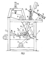
- the winder shown in Figure 1 can be used for the formation of rolls of glass wool felts or similar compressible products.
- This reel can be placed directly at the end of a production line for these felts.
- the manner in which the fibers are produced is immaterial to the invention. It suffices, especially after the polymerization step of the binder which makes the fibers adhere to each other, that the felt thus formed has good resilience, in other words that it can undergo a significant compression and then resume most of its initial thickness when it ceases to be compressed.
- the felt 1 progresses on the conveyor 2 in the direction indicated by the arrow.
- the conveyor 2 is set in motion by the motor 3 by means of a belt 4 and the drive drum 5.
- the arm 7 carries a conveyor 11 whose end furthest from the axis 9 is located opposite the end of the conveyor 2 at a short distance from the latter. This distance is as short as possible. Its purpose is to facilitate the initiation of the winding by leaving the felt a minimum of space. This distance must however be sufficient to avoid any risk of friction of the conveyors on one another.
- the conveyor 11 is inside an envelope which is only partially shown in the figure for reasons of clarity.
- the limit of the missing part of the envelope is indicated in dotted lines.
- the faces of the conveyors form an angle of less than 90 ° between them.
- This angle is advantageously between 40 and 80 ° and preferably close to 60 ".
- the conveyor 11 is set in motion by the motor 3, by means of a deformable articulated transmission not shown.
- This articulated transmission is such that it allows the tilting of the arm 7 in the manner described below.
- a jack 13 fixed on a support 33 secured to the chassis 6 makes it possible to tilt the arm 7 so as to separate the end of the conveyor 11 from that of the conveyor 2. In the separated position, the distance separating the two conveyors is greater than the diameter of the felt rollers formed to allow the evacuation of the latter.
- the power supply and the control of the jack 13 are not shown.
- the arm 8 comprises two identical parts located on either side of the arm 7 which they frame.
- the lower ends of the two parts of the arm 8 carry two rollers 14 and 15. These rollers are rotated by means of chains, not shown, located along the arm itself.
- the drive is provided by the motor 3.
- the return wheels of the movement of the chains are coaxial with the axis of rotation 10 of the arm 8, so that a movement of the arm 8 can be done without modifying the tension of the chains .
- a variable speed drive is interposed on the transmission system.
- the arm 8 is extended by a counterweight 17 which balances it and makes its movement easier.
- the space in which the felt strip is wound is delimited by two conveyors and a roller. If necessary, at least one of the conveyors can be replaced by a roller fulfilling the same function. Despite a slightly more complicated mechanism, the use of conveyors is advantageous for several reasons.
- a first reason is due to the fact that even if the rollers are of relatively large dimensions, the contact with the wound strip takes place on a convex surface which tends to deform the felt more than does a conveyor which has a flat surface. This is important for proper roll formation.
- the third support point on the compression roller also moves in a movement which maintains this good arrangement.
- the support points are equidistant from each other.
- the distance from the compression roller to the axis of rotation is sufficiently large and the position of this axis is preferably such that the displacement takes place substantially along the bisector of the angle of the two conveyors.
- a pneumatic cylinder 18 mounted on a support 19 secured to the chassis 6 makes it possible to move the arm 8 through its rod 20.
- the pneumatic cylinder intervenes purely passively.
- the arm 8 pushed back by the wound felt 21, pivots about the axis 10.
- the air pressure in the jack increases and, by reaction, the pressure on the felt increases.
- the movement of the arm, and consequently the pressure exerted on the felt follow a preset program.
- the position of the arm 8 is precisely defined at each instant.
- the motor device 18 is thus advantageously a hydraulic cylinder or an electric motor controlled in position. Their power is chosen to be high enough so that the pressure exerted by the felt is practically without influence on the operation of the compression roller, unlike what occurs with the prior pneumatic cylinder.
- the supply of the hydraulic cylinder in the case of the invention is carried out in the traditional way by a proportional distributor and a hydraulic group not shown.
- the movement of the arm 8 is a function of the length of the wound felt and so that the thickness of each turn of the winding is practically constant.
- the winder according to the invention thus comprises at least means making it possible to determine at any time the length of felt wound, a sensor determining with precision the position of the arm 8, and calculation means in which the movement program of the arm 8 is put in black.
- the calculation means receive the signals relating to the length of felt and of the position signals of the arm, and elaborate in response a position instruction of this arm, instruction which is executed by the motor means (hydraulic cylinder, electric motor) indicated above. .
- the signal is transmitted to programmable calculation means 23.
- the calculation means 23 also receive from a sensor 24, for example a tachometric dynamo, a signal for the speed of progression of the conveyor 2 and consequently of the felt.
- a sensor 24 for example a tachometric dynamo
- the combination of the felt arrival signal and the speed gives the length of the coiled felt.
- the calculation means also receive a signal from a position encoder 25 determining the angle of the arm 8 carrying the compression roller with respect to a reference position.
- an additional sensor makes it possible to measure the initial height of the compression roller with respect to the conveyor 2. This determination is necessary when this height is modified to take account of changes in thickness of the products treated.
- Figure 1 the means for changing the initial height of the axis 10 of the arm 8 are shown at 29. This is for example a system driven by a screw motor.
- the means of calculation as a function of these data and of the control algorithm introduced into memory establish instructions which are sent to the commands 26 controlling the operation of the motor means 27 actuating the displacement of the compression roller, and also the means 28 actuating the movement of the back conveyor 11.
- the felt strip 1 carried by the conveyor 2 passes in front of the photoelectric cell 22 and triggers a measurement of the time elapsed in the operating cycle.
- the felt strip Before entering the space defined for winding, the felt strip is compressed by means of the roller 15.
- the roller 15 is carried by the arm 8. It is driven by the compression roller 14 and rotates in the opposite direction.
- the roller 15 makes it possible to prevent the felt from coming into contact with the roller 14 when it is introduced into the space in which the winding takes place. Indeed, the direction of rotation of the roller 14 is such that it would tend to repress the felt instead of facilitating its entry into this space.
- the speed of rotation of the roller 15 is adjusted so that the speed at the periphery corresponds substantially to that of the conveyor 2.
- the felt driven by the conveyor 2 strikes the back conveyor 11 and folds back on itself. From the conveyor 11, the end of the felt is directed towards the compression roller 14. The roller 14 forces the felt to bend again on itself. From the roller 14, the end of the felt is returned to the conveyor 2 where it comes into contact with the upper face of the felt.
- a first loop of felt is thus formed.
- the roller then progresses in successive thicknesses which are added to each other.
- the compression roller 14 moves away from its initial position to take account of the ac increase in volume of the rolled-up felt.
- the movement is silent in the direction indicated by the arrow F by tilting the arm 8.
- the movement is controlled in a programmed fashion so that all the turns of the roll formed have substantially the same thickness.
- the thickness imposed is not necessarily exactly that which is found in the felt roll. It is indeed necessary to take into account the elasticity of the product and the deformations it presents during winding. In practice, the thickness imposed is generally less than that of the felt in the completed roll, and which is no longer maintained by the conveyors and the compression roller.
- the arm 8 By deviating from its initial position, the arm 8 progressively increases the distance between the conveyor 2 and the roller 15. This distance becomes such that from a certain moment the roller 15 ceases to be in contact with the felt. The distance is then also sufficient so that the felt carried by the conveyor 2 does not come into contact with the compression roller 14.
- a paper or polymer envelope is deposited on one of the faces of the felt.
- the length of this envelope is such that it completely covers the exterior surface of the roller in a known manner.
- the establishment of the envelope on the felt being made, the conditioning of the felt strip is completed for example by gluing the envelope so that it maintains the felt in its final compressed form.
- the arm 7 moved by the jack 13 rocks.
- the felt roll which is driven by the conveyor 2 is discharged through the opening cleared between the conveyors 2 and 11.
- the arm 8 is returned to its initial position. Finally, the arm 7 is also returned to the working position. The reel is ready for processing a new strip of felt.
- the envelope introduction system is shown diagrammatically in FIG. 1.
- the cut and partially glued sheets coming from a dispenser, not shown, and also controlled by the calculation means, are conveyed by a conveyor belt 30. They then pass on belts 31, in known manner, so that they are deposited on the end of the upper face of the felt strip at the moment when the latter will enter the winding space.
- the envelope sheet is driven by the felt. It is taken in the last turn. This sheet extends beyond the end of the felt strip over a length greater than that of the periphery of the roll, so that it completely envelops it.
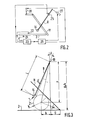
- FIG. 3 are shown schematically the back conveyor 11, the horizontal conveyor 2, the compression roller 14 and the arm 8.
- the movement of the arm 8 carrying the compression roller must be such that at all times the radius r of the roller already formed for a length 1 of the felt is: is :
- a calculation based on the geometry of the system as presented in FIG. 3 makes it possible to express the variations of the angle A made by the arm 8 with the vertical at any time.
- the calculation means check at all times that the position of the arm actually meets this condition.
- the geometric conditions which have just been considered constitute only a series of parameters taken into account by the calculation means.
- the main other parameters are in particular those which depend on the nature of the felt wound: initial thickness, total length of the strip, mass per unit area, admissible compression ratio, etc.
- the values of these parameters can be entered directly by the operator, either separately or globally, by referring to a code to which all the values stored in memory correspond, each product having its own code.
- the packaging technique according to the invention was the subject of tests on an industrial line for the production of glass fiber felts.
- the felts used consist of fibers produced by a centrifugation technique.
- the molten material is passed through a centrifuge carrying at its periphery a large number of orifices of small diameters. Under the effect of centrifugal force the material is projected through these orifices out of the centrifuge in the form of filaments. These fine filaments are further drawn by hot gas streams running along the periphery of the centrifuge at high speed.
- the fibers produced are collected on a conveyor. On their way to the conveyor they are coated with a binder. The fibers collected are then passed through a treatment chamber in which the binder is polymerized. The sheet of fibers thus formed is cut to the appropriate dimensions. It is this sheet which is wound in the manner described according to the invention.
- centrifugal devices In industrial plants, usually several centrifugal devices are aligned over the same conveyor.
- the felts prepared during these tests are relatively light; their density varies from 6.8 kg / m 3 to 10.8 kg / m 3 .
- the fibers are fine; the micronaire is either 2.5 / 5 g or 3.1 / 5 g.
- the felts contain 4.5% by weight of binder.
- the nominal thickness that is to say the thickness guaranteed to the user, is for all these products 90 nm.
- an additional thickness is systematically provided in the felt before winding.
- the thickness measurements are carried out in accordance with French standard NF-B-20.101. According to this standard, the thickness is measured under a conventional pressure of 50 N / m 2 . Measurements are made every 250 mm lengthwise, and 175 mm from the edges widthwise.
- the values given in the table correspond to the average of the values measured over the entire length of the felt strip.
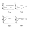
- the values plotted on the graphs correspond respectively to the averages determined over five equal sections distributed over the entire length of the strip of felt.
- the results are written from left to right, the left part representing the end located in the center of the roll and the right part representing the end.
- the thickness recovery is generally slightly increasing from the part corresponding to the first turns to that corresponding to the final turns of the roller. This can possibly be explained by the fact that in the program used for these tests, the only condition fixed is a constant thickness of turn. To take account of the variable radius of curvature as the winding and the resulting deformation differences, it may be preferable to program the winding so that the thickness of the turns is slightly decreasing from start to the end of the formation of the rollers.
- the means proposed according to the invention also have the remarkable feature that they allow a very convenient modification of operating conditions. For this, it suffices to modify or complete the instruction program stored in the calculation means. No intervention is necessary on the mechanical elements of the device.
Landscapes
- Winding Of Webs (AREA)
- Controlling Rewinding, Feeding, Winding, Or Abnormalities Of Webs (AREA)
- Treatment Of Fiber Materials (AREA)
- Casting Or Compression Moulding Of Plastics Or The Like (AREA)
- Dry Formation Of Fiberboard And The Like (AREA)
- Battery Electrode And Active Subsutance (AREA)
- Press Drives And Press Lines (AREA)
Priority Applications (1)
| Application Number | Priority Date | Filing Date | Title |
|---|---|---|---|
| AT84402107T ATE29469T1 (de) | 1983-10-21 | 1984-10-19 | Wickler mit gesteuerter zusammenpressung. |
Applications Claiming Priority (2)
| Application Number | Priority Date | Filing Date | Title |
|---|---|---|---|
| FR8316758A FR2553744B1 (fr) | 1983-10-21 | 1983-10-21 | Enrouleuse a compression asservie |
| FR8316758 | 1983-10-21 |
Publications (2)
| Publication Number | Publication Date |
|---|---|
| EP0140785A1 true EP0140785A1 (de) | 1985-05-08 |
| EP0140785B1 EP0140785B1 (de) | 1987-09-09 |
Family
ID=9293371
Family Applications (1)
| Application Number | Title | Priority Date | Filing Date |
|---|---|---|---|
| EP84402107A Expired EP0140785B1 (de) | 1983-10-21 | 1984-10-19 | Wickler mit gesteuerter Zusammenpressung |
Country Status (20)
| Country | Link |
|---|---|
| US (1) | US4583697A (de) |
| EP (1) | EP0140785B1 (de) |
| JP (1) | JPH07100556B2 (de) |
| KR (1) | KR930005916B1 (de) |
| AR (1) | AR242365A1 (de) |
| AT (1) | ATE29469T1 (de) |
| AU (1) | AU576528B2 (de) |
| BR (1) | BR8405295A (de) |
| CA (1) | CA1268110A (de) |
| DE (1) | DE3465964D1 (de) |
| DK (1) | DK164220C (de) |
| ES (1) | ES536911A0 (de) |
| FI (1) | FI74925C (de) |
| FR (1) | FR2553744B1 (de) |
| GR (1) | GR80722B (de) |
| IE (1) | IE55778B1 (de) |
| IN (1) | IN162373B (de) |
| NO (1) | NO159160C (de) |
| TR (1) | TR22202A (de) |
| ZA (1) | ZA848187B (de) |
Cited By (4)
| Publication number | Priority date | Publication date | Assignee | Title |
|---|---|---|---|---|
| EP0941952A1 (de) * | 1998-03-09 | 1999-09-15 | Techint Compagnia Tecnica Internazionale S.P.A. | Maschine zum Aufrollen faseriger kompressibler Materialien |
| EP0949172A1 (de) * | 1998-04-07 | 1999-10-13 | Techint Compagnia Tecnica Internazionale S.P.A. | Apparat zum Aufrollen von zusammenpressbaren Faserstoffmaterialien |
| FR2991301A1 (fr) * | 2012-06-04 | 2013-12-06 | Saint Gobain Isover | Dispositif enrouleur |
| CN116534624A (zh) * | 2023-05-05 | 2023-08-04 | 东莞市恒耀超音波设备有限公司 | 一种压缩浴巾压缩制造设备 |
Families Citing this family (19)
| Publication number | Priority date | Publication date | Assignee | Title |
|---|---|---|---|---|
| NZ213958A (en) * | 1984-10-30 | 1987-11-27 | Rollsponge Int Ltd | Wrapping foam material into tubular packages |
| GB8511923D0 (en) * | 1985-05-10 | 1985-06-19 | Flexitallic Ltd | Gaskets |
| FR2595673B1 (fr) * | 1986-03-11 | 1988-11-04 | Saint Gobain Isover | Perfectionnements aux enrouleuses a compression |
| JPS63185759A (ja) * | 1987-01-26 | 1988-08-01 | Kaneda Kikai Seisakusho:Kk | 損紙処理装置 |
| FR2616137B1 (fr) * | 1987-06-03 | 1990-08-03 | Saint Gobain Isover | Perfectionnements aux enrouleuses a compression de bandes de materiaux compressibles |
| FR2685904A1 (fr) * | 1992-01-07 | 1993-07-09 | Saint Gobain Isover | Rouleau de matelas fibreux comprime, methode et dispositif pour l'obtenir. |
| US5305963A (en) * | 1992-12-03 | 1994-04-26 | Schuller International, Inc. | Method and apparatus for forming rolls from strips of compressible material |
| AUPM687394A0 (en) * | 1994-07-18 | 1994-08-11 | Strathayr Pty. Limited | Roll up tray |
| US5832696A (en) * | 1994-09-21 | 1998-11-10 | Owens Corning Fiberglas Technology, Inc. | Method and apparatus for packaging compressible insulation material |
| FR2731687B1 (fr) * | 1995-03-17 | 1997-04-25 | Tictor Sa | Dispositif enrouleur pour la formation d'un rouleau fibreux comprime |
| ZA981514B (en) * | 1997-03-07 | 1998-08-28 | Saint Gobain Isover | Winding machine for fibrous mats |
| US6755940B2 (en) * | 2001-12-20 | 2004-06-29 | Kimberly-Clark Worldwide, Inc. | Method and apparatus for caliper control of a fibrous web |
| US6887343B2 (en) * | 2002-12-20 | 2005-05-03 | Fleetguard, Inc. | Filter coating, winding, finishing and manufacturing system |
| US7100862B2 (en) * | 2003-09-03 | 2006-09-05 | Ottawa Fibre, Inc. | Roll-up machine and method |
| FI122646B (fi) * | 2007-11-28 | 2012-05-15 | Paroc Oy Ab | Menetelmä ja laite mineraalivillarullien muodostamiseksi |
| CN104058144A (zh) * | 2014-06-27 | 2014-09-24 | 苏州天脉导热科技有限公司 | 一种重型打包装置 |
| WO2018138561A1 (en) * | 2017-01-30 | 2018-08-02 | Ortho-Space Ltd. | Processing machine and methods for processing dip-molded articles |
| DE102019120122A1 (de) * | 2019-07-25 | 2021-01-28 | Saint-Gobain Isover G+H Ag | Verfahren zum Aufwickeln einer Materialbahn, insbesondere aus einem kompressiblen, zusammenpressbaren Material sowie Vorrichtung zum Durchführen des Verfahrens |
| US11787655B2 (en) | 2020-09-28 | 2023-10-17 | C3 Corporation | Variable roll cage machine and process |
Citations (3)
| Publication number | Priority date | Publication date | Assignee | Title |
|---|---|---|---|---|
| US3991538A (en) * | 1975-01-27 | 1976-11-16 | Owens-Corning Fiberglas Corporation | Packaging apparatus for compressible strips |
| US4146188A (en) * | 1977-10-31 | 1979-03-27 | E. Fogarty & Company Limited | Method and apparatus for forming a fibrous cylindrical element |
| US4164177A (en) * | 1978-09-07 | 1979-08-14 | Owens-Corning Fiberglas Corporation | Methods and apparatus for rolling material into a package |
Family Cites Families (9)
| Publication number | Priority date | Publication date | Assignee | Title |
|---|---|---|---|---|
| US2353821A (en) * | 1939-02-13 | 1944-07-18 | Paper Patents Co | Apparatus for making compressed wadding rolls |
| US2881984A (en) * | 1956-10-09 | 1959-04-14 | Charles P Dyken | Rolling machine |
| US3098619A (en) * | 1960-12-23 | 1963-07-23 | Beloit Iron Works | Winder drum arrangement |
| JPS6031733B2 (ja) * | 1973-07-06 | 1985-07-24 | 株式会社片岡機械製作所 | 巻取張力制御装置 |
| US3964246A (en) * | 1974-12-17 | 1976-06-22 | Koehring Company | Rotary baler |
| US4025009A (en) * | 1975-01-20 | 1977-05-24 | Johns-Manville Corporation | Blanket or sheet winding apparatus |
| GB1589875A (en) * | 1976-11-17 | 1981-05-20 | Newalls Insulation Co Ltd | Manufacturing of insulation products |
| US4256269A (en) * | 1978-12-28 | 1981-03-17 | Tex-Del, Inc. | Carpet roll forming apparatus and method |
| JPS6041006B2 (ja) * | 1980-07-02 | 1985-09-13 | 住金化工株式会社 | チオシアン酸ナトリウムの回収方法 |
-
1983
- 1983-10-21 FR FR8316758A patent/FR2553744B1/fr not_active Expired
-
1984
- 1984-10-17 TR TR22202A patent/TR22202A/xx unknown
- 1984-10-18 NO NO844167A patent/NO159160C/no not_active IP Right Cessation
- 1984-10-18 CA CA000465802A patent/CA1268110A/fr not_active Expired - Fee Related
- 1984-10-18 FI FI844111A patent/FI74925C/fi not_active IP Right Cessation
- 1984-10-18 IE IE2683/84A patent/IE55778B1/en not_active IP Right Cessation
- 1984-10-18 IN IN727/CAL/84A patent/IN162373B/en unknown
- 1984-10-19 AT AT84402107T patent/ATE29469T1/de not_active IP Right Cessation
- 1984-10-19 GR GR80722A patent/GR80722B/el unknown
- 1984-10-19 DK DK502484A patent/DK164220C/da not_active IP Right Cessation
- 1984-10-19 BR BR8405295A patent/BR8405295A/pt not_active IP Right Cessation
- 1984-10-19 AU AU34517/84A patent/AU576528B2/en not_active Expired
- 1984-10-19 DE DE8484402107T patent/DE3465964D1/de not_active Expired
- 1984-10-19 EP EP84402107A patent/EP0140785B1/de not_active Expired
- 1984-10-19 ZA ZA848187A patent/ZA848187B/xx unknown
- 1984-10-19 ES ES536911A patent/ES536911A0/es active Granted
- 1984-10-20 KR KR1019840006529A patent/KR930005916B1/ko not_active IP Right Cessation
- 1984-10-22 JP JP59220638A patent/JPH07100556B2/ja not_active Expired - Lifetime
- 1984-10-22 US US06/663,401 patent/US4583697A/en not_active Expired - Lifetime
- 1984-10-22 AR AR84298327A patent/AR242365A1/es active
Patent Citations (3)
| Publication number | Priority date | Publication date | Assignee | Title |
|---|---|---|---|---|
| US3991538A (en) * | 1975-01-27 | 1976-11-16 | Owens-Corning Fiberglas Corporation | Packaging apparatus for compressible strips |
| US4146188A (en) * | 1977-10-31 | 1979-03-27 | E. Fogarty & Company Limited | Method and apparatus for forming a fibrous cylindrical element |
| US4164177A (en) * | 1978-09-07 | 1979-08-14 | Owens-Corning Fiberglas Corporation | Methods and apparatus for rolling material into a package |
Cited By (7)
| Publication number | Priority date | Publication date | Assignee | Title |
|---|---|---|---|---|
| EP0941952A1 (de) * | 1998-03-09 | 1999-09-15 | Techint Compagnia Tecnica Internazionale S.P.A. | Maschine zum Aufrollen faseriger kompressibler Materialien |
| EP0949172A1 (de) * | 1998-04-07 | 1999-10-13 | Techint Compagnia Tecnica Internazionale S.P.A. | Apparat zum Aufrollen von zusammenpressbaren Faserstoffmaterialien |
| FR2991301A1 (fr) * | 2012-06-04 | 2013-12-06 | Saint Gobain Isover | Dispositif enrouleur |
| WO2013182777A1 (fr) * | 2012-06-04 | 2013-12-12 | Saint-Gobain Isover | Dispositif enrouleur |
| US9701504B2 (en) | 2012-06-04 | 2017-07-11 | Saint-Gobain Isover | Winding device |
| CN116534624A (zh) * | 2023-05-05 | 2023-08-04 | 东莞市恒耀超音波设备有限公司 | 一种压缩浴巾压缩制造设备 |
| CN116534624B (zh) * | 2023-05-05 | 2023-10-13 | 东莞市恒耀超音波设备有限公司 | 一种压缩浴巾压缩制造设备 |
Also Published As
| Publication number | Publication date |
|---|---|
| FR2553744A1 (fr) | 1985-04-26 |
| DK502484A (da) | 1985-04-22 |
| FR2553744B1 (fr) | 1986-03-28 |
| DK164220C (da) | 1992-10-19 |
| TR22202A (tr) | 1986-09-24 |
| CA1268110A (fr) | 1990-04-24 |
| NO159160C (no) | 1988-12-07 |
| FI74925C (fi) | 1989-02-21 |
| IE842683L (en) | 1985-04-21 |
| FI844111L (fi) | 1985-04-22 |
| JPS60122651A (ja) | 1985-07-01 |
| AU576528B2 (en) | 1988-09-01 |
| ZA848187B (en) | 1985-09-25 |
| AU3451784A (en) | 1985-11-21 |
| KR930005916B1 (ko) | 1993-06-29 |
| NO844167L (no) | 1985-04-22 |
| IN162373B (de) | 1988-05-14 |
| ES8505610A1 (es) | 1985-06-16 |
| NO159160B (no) | 1988-08-29 |
| JPH07100556B2 (ja) | 1995-11-01 |
| DK164220B (da) | 1992-05-25 |
| IE55778B1 (en) | 1991-01-16 |
| FI844111A0 (fi) | 1984-10-18 |
| DE3465964D1 (en) | 1987-10-15 |
| GR80722B (en) | 1985-02-21 |
| EP0140785B1 (de) | 1987-09-09 |
| KR850004620A (ko) | 1985-07-25 |
| ES536911A0 (es) | 1985-06-16 |
| ATE29469T1 (de) | 1987-09-15 |
| DK502484D0 (da) | 1984-10-19 |
| FI74925B (fi) | 1987-12-31 |
| BR8405295A (pt) | 1985-09-03 |
| US4583697A (en) | 1986-04-22 |
| AR242365A1 (es) | 1993-03-31 |
Similar Documents
| Publication | Publication Date | Title |
|---|---|---|
| EP0140785B1 (de) | Wickler mit gesteuerter Zusammenpressung | |
| EP0551228B1 (de) | Verfahren und Vorrichtung zum Komprimieren einer Rolle aus Fasermatte | |
| EP0323296B1 (de) | Verfahren zur Bildung von Zickzackstapeln, ausgehend von einer Endlosbahn aus biegsamem Material und Maschine zur Durchführung dieses Verfahrens | |
| EP0238393B1 (de) | Wickelmaschine zum gleichzeitigen Verdichten | |
| EP0056353B1 (de) | Maschine zum Schneiden, Falten und Fertigstellen von Bögen, ausgegeben aus aufgerollten Bahnen | |
| FR2672878A1 (fr) | Dispositif de bobinage de matieres en bande ou en ruban. | |
| FR2499038A1 (fr) | Procede et dispositif pour aplatir de facon durable des produits imprimes, notamment des journaux, par compression | |
| EP0599787B1 (de) | Verfahren und Vorrichtung zum kontinuierlichen Zuführen von zusammendrückbaren Gegenständen, insbesondere gefalteten Taschentüchern aus Zellstoff, in einer dünnen Kunststoffhülle zu einer Trommel zum Verpacken von Paketen | |
| FR2620117A1 (fr) | Machines diviseuses et reenrouleuses de bande | |
| FR2531941A1 (fr) | Machine pour la decoupe de pieces dans une matiere en bande | |
| FR2521963A1 (fr) | Enrouleur par contact pour feuilles continues | |
| EP0294290B1 (de) | Verfahren zum zusammendrückenden Aufwickeln | |
| EP0734985A1 (de) | Wickelvorrichtung zur Bildung einer zusammengepressten Faserstoff-Rolle | |
| FR2540353A1 (fr) | Dispositif et procede pour confectionner des produits en forme de batonnets de l'industrie de transformation du tabac | |
| EP0638496A1 (de) | Vorrichtung und Verfahren zum Einführen von blattformigem Material in eine Maschine | |
| EP1711423B1 (de) | Aufwickelvorrichtung mit zwei antriebsrollen für durchlaufaufwickelmaschine mit gesteuerter anlegelast der antriebsrollen | |
| FR2595675A1 (fr) | Procede et appareil pour distribuer et enrouler du papier d'empaquetage | |
| FR2577763A1 (fr) | Procede et dispositif d'alimentation d'une bande de papier sur une machine de fabrication de cigarettes double tige | |
| FR2515574A1 (fr) | Dispositif de raccordement par collage pour carton ondule a ondulations croisees | |
| EP0598641A1 (de) | Vorrichtung zum Vereinzeln von gestapelten dünnen Gegenständen | |
| EP0049205A2 (de) | Verbinden einer endlosen Folie mit einer kontinuierlich transportierten Matte | |
| EP0290344B1 (de) | Verfahren und Vorrichtung zum Kalandrieren von Glasverbundscheiben | |
| EP0141719B1 (de) | Vorrichtung für das kontinuierliche Herstellen von verschiedenen Artikeln aus mineralischen Fasern | |
| EP0072315A1 (de) | Verfahren und Maschine zur Herstellung eines Rohrförmigen Zylinders aus Karton, insbesondere eines Fasskörpers, und Kartonzylinder durch dieses Verfahren hergestellt | |
| FR2577913A1 (fr) | Machine automatique pour enrouler des elements en forme de feuilles, en particulier des peaux |
Legal Events
| Date | Code | Title | Description |
|---|---|---|---|
| PUAI | Public reference made under article 153(3) epc to a published international application that has entered the european phase |
Free format text: ORIGINAL CODE: 0009012 |
|
| AK | Designated contracting states |
Designated state(s): AT BE CH DE FR GB IT LI LU NL SE |
|
| 17P | Request for examination filed |
Effective date: 19850605 |
|
| 17Q | First examination report despatched |
Effective date: 19860124 |
|
| R17C | First examination report despatched (corrected) |
Effective date: 19860811 |
|
| GRAA | (expected) grant |
Free format text: ORIGINAL CODE: 0009210 |
|
| AK | Designated contracting states |
Kind code of ref document: B1 Designated state(s): AT BE CH DE FR GB IT LI LU NL SE |
|
| REF | Corresponds to: |
Ref document number: 29469 Country of ref document: AT Date of ref document: 19870915 Kind code of ref document: T |
|
| REF | Corresponds to: |
Ref document number: 3465964 Country of ref document: DE Date of ref document: 19871015 |
|
| ITF | It: translation for a ep patent filed |
Owner name: DR. ING. A. RACHELI & C. |
|
| GBT | Gb: translation of ep patent filed (gb section 77(6)(a)/1977) | ||
| PLBE | No opposition filed within time limit |
Free format text: ORIGINAL CODE: 0009261 |
|
| STAA | Information on the status of an ep patent application or granted ep patent |
Free format text: STATUS: NO OPPOSITION FILED WITHIN TIME LIMIT |
|
| 26N | No opposition filed | ||
| ITTA | It: last paid annual fee | ||
| PGFP | Annual fee paid to national office [announced via postgrant information from national office to epo] |
Ref country code: LU Payment date: 19931101 Year of fee payment: 10 |
|
| EPTA | Lu: last paid annual fee | ||
| PG25 | Lapsed in a contracting state [announced via postgrant information from national office to epo] |
Ref country code: LU Free format text: LAPSE BECAUSE OF NON-PAYMENT OF DUE FEES Effective date: 19941019 |
|
| EAL | Se: european patent in force in sweden |
Ref document number: 84402107.1 |
|
| REG | Reference to a national code |
Ref country code: GB Ref legal event code: IF02 |
|
| PGFP | Annual fee paid to national office [announced via postgrant information from national office to epo] |
Ref country code: AT Payment date: 20021011 Year of fee payment: 19 |
|
| PGFP | Annual fee paid to national office [announced via postgrant information from national office to epo] |
Ref country code: DE Payment date: 20021029 Year of fee payment: 19 |
|
| PGFP | Annual fee paid to national office [announced via postgrant information from national office to epo] |
Ref country code: SE Payment date: 20031007 Year of fee payment: 20 |
|
| PGFP | Annual fee paid to national office [announced via postgrant information from national office to epo] |
Ref country code: NL Payment date: 20031008 Year of fee payment: 20 Ref country code: FR Payment date: 20031008 Year of fee payment: 20 |
|
| PGFP | Annual fee paid to national office [announced via postgrant information from national office to epo] |
Ref country code: GB Payment date: 20031016 Year of fee payment: 20 |
|
| PGFP | Annual fee paid to national office [announced via postgrant information from national office to epo] |
Ref country code: CH Payment date: 20031017 Year of fee payment: 20 |
|
| PG25 | Lapsed in a contracting state [announced via postgrant information from national office to epo] |
Ref country code: AT Free format text: LAPSE BECAUSE OF NON-PAYMENT OF DUE FEES Effective date: 20031019 |
|
| PGFP | Annual fee paid to national office [announced via postgrant information from national office to epo] |
Ref country code: BE Payment date: 20031031 Year of fee payment: 20 |
|
| PG25 | Lapsed in a contracting state [announced via postgrant information from national office to epo] |
Ref country code: DE Free format text: LAPSE BECAUSE OF NON-PAYMENT OF DUE FEES Effective date: 20040501 |
|
| PG25 | Lapsed in a contracting state [announced via postgrant information from national office to epo] |
Ref country code: LI Free format text: LAPSE BECAUSE OF EXPIRATION OF PROTECTION Effective date: 20041018 Ref country code: GB Free format text: LAPSE BECAUSE OF EXPIRATION OF PROTECTION Effective date: 20041018 Ref country code: CH Free format text: LAPSE BECAUSE OF EXPIRATION OF PROTECTION Effective date: 20041018 |
|
| PG25 | Lapsed in a contracting state [announced via postgrant information from national office to epo] |
Ref country code: NL Free format text: LAPSE BECAUSE OF EXPIRATION OF PROTECTION Effective date: 20041019 |
|
| BE20 | Be: patent expired |
Owner name: *ISOVER SAINT-GOBAIN Effective date: 20041019 |
|
| REG | Reference to a national code |
Ref country code: GB Ref legal event code: PE20 |
|
| REG | Reference to a national code |
Ref country code: CH Ref legal event code: PL |
|
| EUG | Se: european patent has lapsed | ||
| NLV7 | Nl: ceased due to reaching the maximum lifetime of a patent |
Effective date: 20041019 |