EP0139752A1 - Pressure variation detecting type leakage inspection equipment - Google Patents
Pressure variation detecting type leakage inspection equipment Download PDFInfo
- Publication number
- EP0139752A1 EP0139752A1 EP83900963A EP83900963A EP0139752A1 EP 0139752 A1 EP0139752 A1 EP 0139752A1 EP 83900963 A EP83900963 A EP 83900963A EP 83900963 A EP83900963 A EP 83900963A EP 0139752 A1 EP0139752 A1 EP 0139752A1
- Authority
- EP
- European Patent Office
- Prior art keywords
- pressure
- article
- inspected
- value
- inspection equipment
- Prior art date
- Legal status (The legal status is an assumption and is not a legal conclusion. Google has not performed a legal analysis and makes no representation as to the accuracy of the status listed.)
- Granted
Links
Images


Classifications
-
- G—PHYSICS
- G01—MEASURING; TESTING
- G01M—TESTING STATIC OR DYNAMIC BALANCE OF MACHINES OR STRUCTURES; TESTING OF STRUCTURES OR APPARATUS, NOT OTHERWISE PROVIDED FOR
- G01M3/00—Investigating fluid-tightness of structures
- G01M3/02—Investigating fluid-tightness of structures by using fluid or vacuum
- G01M3/26—Investigating fluid-tightness of structures by using fluid or vacuum by measuring rate of loss or gain of fluid, e.g. by pressure-responsive devices, by flow detectors
- G01M3/32—Investigating fluid-tightness of structures by using fluid or vacuum by measuring rate of loss or gain of fluid, e.g. by pressure-responsive devices, by flow detectors for containers, e.g. radiators
- G01M3/3236—Investigating fluid-tightness of structures by using fluid or vacuum by measuring rate of loss or gain of fluid, e.g. by pressure-responsive devices, by flow detectors for containers, e.g. radiators by monitoring the interior space of the containers
- G01M3/3263—Investigating fluid-tightness of structures by using fluid or vacuum by measuring rate of loss or gain of fluid, e.g. by pressure-responsive devices, by flow detectors for containers, e.g. radiators by monitoring the interior space of the containers using a differential pressure detector
Definitions
- the present-invention relates to leakage inspection equipment by which products or parts, which are required to be free from a fluid leak or to limit a fluid leak within a prescribed range while in use, such as instruments or containers handling fluids, are inspected one after another in their production process to judge whether they are non-defective or defective.
- This leakage inspection equipment is roughly divided into two inspection systems, the one of which applies a positive or negative fluid pressure to the interior of an article under inspection and detects whether a change in the pressure is within a prescribed range, thereby judging whether the article under inspection is non-defective or defective and the other of which applies a positive or negative fluid pressure to each of the article under inspection and a comparison tank and measures a variation in the differential pressure therebetween, thereby judging whether the article under inspection is non-defective or defective.
- a fluid pressure is applied to the article under inspection, a variation in the pressure or differential pressure is monitored for a certain period of time after the fluid pressure reached a predetermined value, and the article being inspected is judged non-defective or defective depending upon whether the variation in the pressure or differential pressure is within a prescribed range.
- air is usually employed as the fluid.
- pneumatic pressure an error is introduced into the measured pressure value or differential pressure owing to various factors such as the temperature of the article under inspection, ambient temperature, humidity, water content adhering to the article under inspection and its slight deformation by pressure.
- the error value is always constant, no particular trouble occurs since it is necessary only to hold the reference value for judgement constant. Since the error contained in the pressure or differential pressure value is caused by the abovesaid various factors, however, a change in each factor incurs a variation in the error value, and it is difficult to predict the variation. Accordingly, in the case of continuously performing the inspection, it is necessary that the reference value for judgement be frequently modified in response to variations in the error value. For such reasons, the prior art has the defect that the leakage inspection cannot be automated.
- An object of the present invention is to provide pressure variation detecting type leakage inspection equipment in which the pressure or differential pressure value is automatically corrected to eliminate the error value, thereby ensuring to automatically perform an appropriate leakage inspection at all times.
- Another object of the present invention is to provide pressure variation detecting type leakage inspection equipment which permits an appropriate leakage inspection from the initial stage of inspection.
- the present invention in leakage inspection equipment in which a fixed fluid pressure is applied to an article to be inspected and detects, in terms of time, variations in the-pressure of the article under inspection, or variations in the differential pressure between the article under inspection and a leak-free comparison tank supplied with the fixed fluid pressure, thereby judging whether the article under inspection is non-defective or defective, there are provided storage means for storing a predetermined number of measured data on the article under inspection judged non-defective, calculating means for calculating a mean value of the measured data stored in the storage means and correcting means for correcting the measured data through using the mean value obtained by the calculating means as a correction value for the measured data on the article being inspected, and a moving mean of a plurality of preceding measured data is utilized as a correction value, by which the tendency of variation in an error value resulting from various factors is detected, thereby ensuring to automatically correct variations in the error value.
- the correction value is automatically corrected in response to the variation.
- an appropriate correction value can always be obtained and the leakage inspection equipment can be automated.
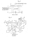
- Fig. 1 is a block diagram explanatory of a conventional leakage inspection equipment
- Fig. 2 is a waveform diagram explanatory of the operation of Fig. 1
- Fig. 3 is a block diagram illustrating an embodiment of the present invention
- Fig. 4 is a block diagram explanatory of a correcting operation in the embodiment of Fig. 3
- Fig. 5 is a block diagram illustrating another embodiment of the present invention
- Fig. 6 is a flowchart explanatory of the operation of Fig. 5
- Fig. 7 is a block diagram illustrating another embodiment of the present invention.
- a flow tube 10 connected to the output side of a pneumatic source 11 is connected via a regulating valve 12 to an electromagnetic valve 14 serving as a control valve and, at the outlet side of the electromagnetic valve 14, the flow tube is divided into two and connected to branches 15-1 and 15-2, respectively.
- a pressure gauge 13 for setting a checking pressure is connected between the outlet of the regulating valve 12 and the inlet of the electromagnetic valve 14.
- the branch 15-1 is connected to one end of a conduit 18 via an electromagnetic valve 16 acting as a control valve, and the other end of the conduit 18 is provided with a mechanism to which is connected an article under inspection 20 which is checked for leakage. Articles 20 to be checked are connected to the mechanism at the end of the conduit 18 one after another for leakage inspection.
- the branch 15-2 is connected to one end of a conduit 19 via an electromagnetic valve 17 serving as a control valve, and the other end of the conduit 19 has been connected thereto a comparison tank 21.
- a differential pressure detector 22 is provided between the conduits 18 and 19 on the side of the outlets of the electromagnetic valves 16 and 17.
- An output signal of the differential pressure detector 22 is applied via an amplifier 31 to a comparator 32, wherein it is compared with an output reference value of a reference signal setting means 33.
- the regulating valve 12 is opened and the pneumatic pressure supplied from the pneumatic source 11 is controlled to assume a predetermined value according to the pressure gauge 13.
- the electromagnetic valves 16 and 17 are opened, from which air of the fixed pressure, set in the open state of the electromagnetic valve 14, is supplied to the article under inspection 20 and the comparison tank 21 through the branches 15-1 and 15-2 and the conduits 18 and 19, respectively.
- This period of operation will herein be referred to as a pressurization or evacuation period, which is indicated by T 1 in Fig. 2A.
- a zero-correction signal 34 is applied to the automatic zero-correction type amplifier 31 connected to the differential pressure detector 22, by which the output of the amplifier 31 is preset to zero, and a certain period of time T 3 after the zero setting, the output signal of the amplifier 31 is read out.
- the period of time T 3 from the zero-setting time point to the readout of the amplifier output will hereinafter be referred to as the measuring time.
- a sequence of the period T 1 in which to open the electromagnetic valves 16 and 17 for pressurization, the period T 2 in which to close the electromagnetic valves 16 and 17 for pressure stabilization and the period T 3 in which to set the amplifier 31 to zero for readout of its output will hereinafter be referred to as a measurement cycle.
- the switching of the periods T 1 , T 2 and T 3 is effected by sequence control means.
- the output signal from the amplifier 31 goes to.zero ideally in.a fixed measurement time.
- the output signal yielded in the fixed measurement time T assumes a value substantially proportional to the negative or positive leakage.
- the reference signal from the reference signal setting means 33 and the output signal of the amplifier 31 are compared by the comparator 32, from which is obtained an output which indicates whether the article under inspection is defective or non-defective depending upon whether the output signal of the amplifier exceeds the reference signal.
- deformation of rubber for sealing an opening of the article being inspected also constitutes another factor.
- the error base on these factors inevitably changes every hour, every day, every season or every year.
- the conventional pressure variation detecting or differential pressure detecting leakage inspection equipment is accompanied by the error induced by the factors which vary with time, and hence calls for frequent modifications of the output reference value of the reference signal setting means 33 for judgement. This necessitates continuous attendance of an operator on the inspection equipment and is labor-consuming, and hence is undesirable; in addition, with this manipulation, high precision leakage inspection is difficult to achieve.
- Fig. 3 is a block diagram illustrating an embodiment of the present invention.
- the output end of the differential pressure detector 22 is connected to the input end of the amplifier 31, the output end of which is connected the input end of an A-D converter 41.
- the differential pressure detector 22, the amplifier 31 and the A-D converter 41 constitute measuring means.
- the output end of the A-D converter 41 is connected via a data correcting means 47 to input ends of an output display 48 and a comparing means 49.
- the storage means 42 comprises error upper-limit value setting means 42a, gate means 42b which permits the passage therethrough of output data of the A-D converter 41 when it is smaller than an error upper-limit value AP m set in the setting means 42a and when the comparing means 49 judges that the article being inspected is non-defective and which inhibits the passage therethrough of the output data of the A-D converter 41 when it is larger than the error upper-limit value ⁇ P M or when the comparing means 49 judges that the article being inspected is defective, and an error storage 42c for storing only the data having passed through the gate means 42b. Therefore, the error storage 42c stores error data only in the case where it is smaller than the error upper-limit value AP m set in the setting means 42a and the comparing means 49 judges that the article under inspection is non-defective.
- the error data stored in the error data storage 42c is read out therefrom corresponding to the number of data set in sample-number setting means 43 and is provided to average value calculating means 44.
- the average value calculating means 44 calculates an average value of the data provided from the error data storage 42c and supplies the average value via a change-over switch 52 to a correction value converting means 45.
- the correction value converting means 45 calculates a correction value on the basis of, for
- the measurement time T 3 and the average error value AP supplied from the average value calculating means 44, T being an elapsed time and assumed to vary from 0 to T 3 .
- the correction value 6 is applied to the data correcting means 47 for correcting the measured data ⁇ Pi from the D-A converter 41.
- an initial correction value setting means 53 is provided at the input side of the correction value converting means 45, in addition to the average value calculating means 44. Only for first measurement immediately after the start of operation, the measured data is corrected by a correction value set in the initial correction value setting means 53, and for the subsequent measurement, an average value of the measured data is used as a correction value.
- the average value is an average value of measured data of the number of samples set in the sample-number setting means 43. That is, in the case of the number of samples is set to N, the present measured data and the preceding N measured data are averaged. In the next measurement cycle, the oldest measured data is removed but instead the immediately preceding measured data is added and a total of N measured data are always averaged. This is commonly referred to as a moving average. Until the number of error data stored in the error storage reaches the N, an average value of the stored data is computed.
- Reference numeral 54 indicates control means for sequence-controlling operations of the respective parts.
- the operation of the pressure variation detecting type leakage inspection equipment of the present invention is as follows: At the start of operation, the change-over switch 52 is connected to the side of the initial correction value setting means 53. In the initial correction value setting means 53 is set a final correction value obtained on the previous day or an empirically obtained correction value fit for the season. With reference to Fig. 4, the correcting operation will be described.
- D 1 , D 2 , D 3 , ... D are measured data obtained in respective measurement cycles. Of the measured data D 1 to D nt for example, the data D i which exceeds the error upper-limit value ⁇ P M is inhibited by the gate means 42b from passing therethrough, and hence is not stored in the storage 42c.
- d 1 to ⁇ n indicate correction values for correcting the measured data D I to D n , respectively.
- the first correction value ⁇ 1 is provided from the initial correction value setting means 53, and the measured data D 1 is corrected by the correction value ⁇ 1 , thereby obtaining corrected data ⁇ P 1 shown in Fig. 4C.
- the corrected data P 1 is applied to the comparing means 49, wherein it is compared with a limit value ⁇ P S from a judgement limit setting means 50. If the corrected data ⁇ P 1 is within the limit, then a non-defective signal 51 is yielded from the comparing means 49.
- the corrected data ⁇ P 1 is also provided to the display 48, in addition to the comparing means 49, by which the corrected data value (a value corresponding to the differential pressure) is displayed.
- the change-over switch 52 is connected to the side of the average value calculating means 44. Since the storage 42c has stored therein only the first measured data value D 1 , this measured data value D 1 is used as the correction value ⁇ 2 for the second measured data D 2 . In the third measurement, since the first and second measured data D 1 and D 2 are stored in the error storage 42c, the average value calculating means 44 calculates an average value ⁇ 3 of the measured data D 1 and D 2 , and the average value ⁇ 3 is supplied to the correction value converting means 45 for correcting the third measured data D 3 . If corrected data ⁇ P 3 is smaller than the limit value ⁇ P S , the comparing means 49 produces the non-defective signal 51.
- the measured data D 4 is corrected through using an average value ⁇ 4 of the measured data D 1 , D 2 and D 3 .
- corrected data AP4 is obtained, and if the data AP4 exceeds the limiti value ⁇ P S , then the comparing means 49 yields a defective signal 51'.
- the measured data D 4 is not input into the storage 42c. Accordingly, the average value ⁇ 4 is used again for the next measured data D 5 .
- the number of correction data increases one by one until the number of samples stored in the storage 42c reached the number N set in the sample-number setting means 43. After the number of samples has once reached the N, an average value for each subsequent measurement is computed from the latest and previous measured data except data preceding the latest one by the set number of samples, N.
- the present invention even if the error slightly varies during inspection, the error variations are averaged and used as a correction value, ensuring to carry out an appropriate correction at all times. Accordingly, a high precision leakage test can be achieved continuously and automatically.
- the correction value converting means 34 is calculated in the correction value converting means 34 and the correction value 6 is so corrected as to gradually increase with the lapse of time, so that the correction value 6 and the measured data output from the A-D converter 41 both increase substantially equally. Therefore, the corrected data at any point of time can be held at a small value. For this reason, even if the limit value set in the judgement limit setting means 50 is selected small, the corrected data at any points of time in the measurement period T 3 does not exceed the limit value ⁇ P S in the case of the article being inspected being non-defective. This permits to set the limit value ⁇ P S small and ensures a highly accurate leakage test. Accordingly, the present invention is of great utility when put to practical use.
- Fig. 5 illustrates the case where the respective parts shown in Fig. 3 are formed by a microcomputer.
- reference numeral 55 indicates a microcomputer.
- the microcomputer 55 can be made up of a central processor 56, a ROM 57, a RAM 58, an input port 59 and an output port 61, as is well-known.
- To the input port 59 is supplied digital measured data obtained by amplifying analog measured data from the differential pressure detector 22 by means of the amplifier 31 and then A-D converting the amplified output by means of the A-D converter 41.
- the central processor 56 inputs thereinto the measured data which are output from the A-D converter 41 at regular time intervals, for example, at time intervals of about 10 milliseconds.
- a setting means 62 In addition to the A-D converter 41. To the setting means 62 are connected the error upper-limit setting means 42a, the sample-number setting means 43 for computing an average value, the judgement limit setting means 50 and the initial correction value setting means 53, as described previously in connection with Fig. 3. The values set in these setting means 42a, 43, 50 and 53 are input into the central processor 56, wherein they are stored at specified addresses of the RAM 58.
- Fig. 6 shows a flowchart explanatory of the sequence of operation of the embodiment depicted in Fig. 5.
- step (1) the set values of the setting means 42a, 43, 50 and 53 are input into the RAM 58, as mentioned above.
- step (2) the A-D converted value is input.
- step (3) it is judged whether the A-D converted value is smaller than the error upper-limit value AP M .
- This judgement step (3) corresponds to the gate means 42b shown in Fig. 3, and when the A-D converted value is larger than the error upper-limit value AP MP the process jumps to step (14), wherein the defective signal 51' is produced.
- step (4) the A-D converted value is input into the RAM 58.
- step (5) it is judged whether the current measurement cycle is a first one. If the measurement cycle is decided to be the first one, then the initial correction value is read out in step (6).
- step (5) In case it is decided in step (5) that the measurement cycle is not the first one, the process jumps to step (11), in which it is judged whether the number of measurement cycles is larger or smaller than the number N set in the sample-number setting means 43. In the case where it is decided that the number of measurement cycles is smaller than the number N set in the sample-number setting means 43, a mean value of measured data input into the RAM 48 is calculated in step (12).
- step (11) When it is judged in step (11) that the number of measurement cycles is larger than the number N set in the sample-number setting means 43, the data preceded by N corresponding to the set number N is discarded and a mean value is computed of measured data including the newly obtained A-D converted value in step (13).
- step (7) is calculated using the 3 mean value or the initial correction value AP, thereby obtaining such a correction value 6 that gradually increases with time. Accordingly, this step (7) corresponds to the correction value converting means 45 shown in Fig. 3.
- step (8) the A-D converted value is corrected by the correction value obtained in step (7). Accordingly step (8) corresponds to the data correcting means 47 shown in Fig. 3.
- step (9) it is judged whether the corrected data is within the judgement limit, and if so, the non-defective signal 51 is yielded in step (10).
- step (14) the process jumps to step (14), in which the defective signal 51' is produced.
- the above sequence operation is performed by a program stored in the ROM 57 forming the microcomputer 55.
- the present invention has been described in connection with the differential pressure variation detecting type leakage inspection equipment, the invention is also applicable to a leakage inspection equipment of the type that applies a positive or negative fluid pressure to the article under inspection 20 and monitors variations in the fluid pressure to judge whether the article being inspected 20 is non-defective or defective, as explained at the beginning of this specification.
- Fig. 7 illustrates its example.
- reference numeral 63 indicates a pressure detector.
- the fluid pressure applied to the, article under inspection 20 is measured by the pressure detector 63, zero-setting is effected in the amplifier 31 and pressure variations from the zero point are subjected to an A-D conversion for input into the microcomputer 55.
- This system permits simplification of the fluid supply structure in the measuring means, and hence possesses the advantage of low manufacturing costs.
- leakage inspection equipment of the type which applies a fluid pressure to the interior of the article under inspection there is another type of leakage inspection equipment which, for example, when an article to be inspected is small like a water-proof wrist watch, applies a fixed positive or negative pressure to the interior of a leak-free container containing the article to be inspected and variations in the pressure are monitored from the moment of applying the fixed pressure to judge the presence or absence of leakage in the article being inspected 20.
- the present invention is applicable to this type of leakage inspection equipment as well,
Abstract
Description
- The present-invention relates to leakage inspection equipment by which products or parts, which are required to be free from a fluid leak or to limit a fluid leak within a prescribed range while in use, such as instruments or containers handling fluids, are inspected one after another in their production process to judge whether they are non-defective or defective.
- Various instruments such as an engine cylinder, a container of a waterproof watch, a gas appliance and so forth are required to be completely free from a gas or liquid leak or to suppress the leakage within a specified limit. To meet this requirement, such instruments or parts are checked for leakage in their manufacturing process.
- As leakage inspection equipment for such a leakage test, pressure variation detecting type leakage inspection equipment has already been put to practical use. This leakage inspection equipment is roughly divided into two inspection systems, the one of which applies a positive or negative fluid pressure to the interior of an article under inspection and detects whether a change in the pressure is within a prescribed range, thereby judging whether the article under inspection is non-defective or defective and the other of which applies a positive or negative fluid pressure to each of the article under inspection and a comparison tank and measures a variation in the differential pressure therebetween, thereby judging whether the article under inspection is non-defective or defective.
- In either system, a fluid pressure is applied to the article under inspection, a variation in the pressure or differential pressure is monitored for a certain period of time after the fluid pressure reached a predetermined value, and the article being inspected is judged non-defective or defective depending upon whether the variation in the pressure or differential pressure is within a prescribed range. In such an inspection, air is usually employed as the fluid. In the case of using pneumatic pressure as the fluid pressure, an error is introduced into the measured pressure value or differential pressure owing to various factors such as the temperature of the article under inspection, ambient temperature, humidity, water content adhering to the article under inspection and its slight deformation by pressure.
- If the error value is always constant, no particular trouble occurs since it is necessary only to hold the reference value for judgement constant. Since the error contained in the pressure or differential pressure value is caused by the abovesaid various factors, however, a change in each factor incurs a variation in the error value, and it is difficult to predict the variation. Accordingly, in the case of continuously performing the inspection, it is necessary that the reference value for judgement be frequently modified in response to variations in the error value. For such reasons, the prior art has the defect that the leakage inspection cannot be automated.
- An object of the present invention is to provide pressure variation detecting type leakage inspection equipment in which the pressure or differential pressure value is automatically corrected to eliminate the error value, thereby ensuring to automatically perform an appropriate leakage inspection at all times.
- Another object of the present invention is to provide pressure variation detecting type leakage inspection equipment which permits an appropriate leakage inspection from the initial stage of inspection.
- According to the present invention, in leakage inspection equipment in which a fixed fluid pressure is applied to an article to be inspected and detects, in terms of time, variations in the-pressure of the article under inspection, or variations in the differential pressure between the article under inspection and a leak-free comparison tank supplied with the fixed fluid pressure, thereby judging whether the article under inspection is non-defective or defective, there are provided storage means for storing a predetermined number of measured data on the article under inspection judged non-defective, calculating means for calculating a mean value of the measured data stored in the storage means and correcting means for correcting the measured data through using the mean value obtained by the calculating means as a correction value for the measured data on the article being inspected, and a moving mean of a plurality of preceding measured data is utilized as a correction value, by which the tendency of variation in an error value resulting from various factors is detected, thereby ensuring to automatically correct variations in the error value.
- Therefore, according to the present invention, even if the error value varies owing to various factors, the correction value is automatically corrected in response to the variation. As a result of this, an appropriate correction value can always be obtained and the leakage inspection equipment can be automated.
- Fig. 1 is a block diagram explanatory of a conventional leakage inspection equipment; Fig. 2 is a waveform diagram explanatory of the operation of Fig. 1; Fig. 3 is a block diagram illustrating an embodiment of the present invention; Fig. 4 is a block diagram explanatory of a correcting operation in the embodiment of Fig. 3; Fig. 5 is a block diagram illustrating another embodiment of the present invention; Fig. 6 is a flowchart explanatory of the operation of Fig. 5; and Fig. 7 is a block diagram illustrating another embodiment of the present invention.
- To facilitate a better understanding of the present invention, a description will be given, with reference to Figs. 1 and 2, of conventional pressure variation type leakage inspection equipment. This example will be described in connection with differential pressure detecting type leakage inspection equipment.
- A
flow tube 10 connected to the output side of apneumatic source 11 is connected via a regulatingvalve 12 to anelectromagnetic valve 14 serving as a control valve and, at the outlet side of theelectromagnetic valve 14, the flow tube is divided into two and connected to branches 15-1 and 15-2, respectively. Apressure gauge 13 for setting a checking pressure is connected between the outlet of the regulatingvalve 12 and the inlet of theelectromagnetic valve 14. - The branch 15-1 is connected to one end of a
conduit 18 via anelectromagnetic valve 16 acting as a control valve, and the other end of theconduit 18 is provided with a mechanism to which is connected an article underinspection 20 which is checked for leakage.Articles 20 to be checked are connected to the mechanism at the end of theconduit 18 one after another for leakage inspection. On the other hand, the branch 15-2 is connected to one end of a conduit 19 via anelectromagnetic valve 17 serving as a control valve, and the other end of the conduit 19 has been connected thereto acomparison tank 21. Adifferential pressure detector 22 is provided between theconduits 18 and 19 on the side of the outlets of theelectromagnetic valves - An output signal of the
differential pressure detector 22 is applied via anamplifier 31 to acomparator 32, wherein it is compared with an output reference value of a reference signal setting means 33. - After the article to be inspected 20 is attached to the end of the
conduit 18 and the leak-free comparison tank 21 is attached to the conduit 19 and theelectromagnetic valve 14 is closed, the regulatingvalve 12 is opened and the pneumatic pressure supplied from thepneumatic source 11 is controlled to assume a predetermined value according to thepressure gauge 13. Next, theelectromagnetic valves electromagnetic valve 14, is supplied to the article underinspection 20 and thecomparison tank 21 through the branches 15-1 and 15-2 and theconduits 18 and 19, respectively. This period of operation will herein be referred to as a pressurization or evacuation period, which is indicated by T1 in Fig. 2A. - When the pressures in the article under
inspection 20 and thecomparison tank 21 have settled down with the lapse of the fixed time T1 after theelectromagnetic valves valves correction signal 34 is applied to the automatic zero-correction type amplifier 31 connected to thedifferential pressure detector 22, by which the output of theamplifier 31 is preset to zero, and a certain period of time T3 after the zero setting, the output signal of theamplifier 31 is read out. The period of time T3 from the zero-setting time point to the readout of the amplifier output will hereinafter be referred to as the measuring time. When theamplifier 31 is set to zero, its sensitivity is switched to high sensitivity, as required. Accordingly, when it is judged whether the article underinspection 20 is good or not, a detection signal from thedifferential pressure detector 22 is amplified by theamplifier 31 for readout. - A sequence of the period T1 in which to open the
electromagnetic valves electromagnetic valves amplifier 31 to zero for readout of its output will hereinafter be referred to as a measurement cycle. The switching of the periods T1, T2 and T3 is effected by sequence control means. - When the article under
inspection 20 is completely gas-tight and leak-free, the output signal from theamplifier 31 goes to.zero ideally in.a fixed measurement time. When the article being inspected 20 leaks, there is obtained such an output signal that its internal pressure, if positive, gradually decreases and, if negative, gradually increases. The output signal yielded in the fixed measurement time T, assumes a value substantially proportional to the negative or positive leakage. - The reference signal from the reference signal setting means 33 and the output signal of the
amplifier 31 are compared by thecomparator 32, from which is obtained an output which indicates whether the article under inspection is defective or non-defective depending upon whether the output signal of the amplifier exceeds the reference signal. - With this conventional pressure variation detecting type leakage test equipment, even if the
comparison tank 21 is exactly identical in shape with the article underinspection 20 and leak-free, the output signal cannot be put into the ideal zero state under the influence of the temperature difference between the article underinspection 20 and thecomparison tank 21, variations in the ambient temperature, slight deformations or distortions in shape, the difference in attached water content and so forth, as mentioned previously. That is to say, owing to these factors, even if the article underinspection 20 does not leak at all, the output signal available within the fixed detection time usually does not assume the ideal zero value but indicates a value ΔP corresponding to a certain positive or negative leakage, as shown in Fig. 2B. - If the error resulting from these factors remains unchanged for each measurement cycle, then it can be precorrected in use. In practice, however, atmosphere conditions in the long-term use, i.e. factors such as ambient temperature, humidity, the temperature of supplied air, the temperatures of the article being inspected 20 and the
comparison tank 21 and their attached water contents undergo gradual variations. - Furthermore, deformation of rubber for sealing an opening of the article being inspected also constitutes another factor. In the case where a number of
articles 20 flowing on a production process line are checked for leakage one after another, the error base on these factors inevitably changes every hour, every day, every season or every year. - The conventional pressure variation detecting or differential pressure detecting leakage inspection equipment is accompanied by the error induced by the factors which vary with time, and hence calls for frequent modifications of the output reference value of the reference signal setting means 33 for judgement. This necessitates continuous attendance of an operator on the inspection equipment and is labor-consuming, and hence is undesirable; in addition, with this manipulation, high precision leakage inspection is difficult to achieve.
- Fig. 3 is a block diagram illustrating an embodiment of the present invention. The output end of the
differential pressure detector 22 is connected to the input end of theamplifier 31, the output end of which is connected the input end of anA-D converter 41. Thedifferential pressure detector 22, theamplifier 31 and theA-D converter 41 constitute measuring means. The output end of theA-D converter 41 is connected via a data correcting means 47 to input ends of anoutput display 48 and a comparingmeans 49. - On the other hand, the output of the
A-D converter 41 is supplied to storage means 42. The storage means 42 comprises error upper-limit value setting means 42a, gate means 42b which permits the passage therethrough of output data of theA-D converter 41 when it is smaller than an error upper-limit value AP m set in the setting means 42a and when the comparing means 49 judges that the article being inspected is non-defective and which inhibits the passage therethrough of the output data of theA-D converter 41 when it is larger than the error upper-limit value ΔPM or when the comparing means 49 judges that the article being inspected is defective, and anerror storage 42c for storing only the data having passed through the gate means 42b. Therefore, theerror storage 42c stores error data only in the case where it is smaller than the error upper-limit value APm set in the setting means 42a and the comparing means 49 judges that the article under inspection is non-defective. - The error data stored in the
error data storage 42c is read out therefrom corresponding to the number of data set in sample-number setting means 43 and is provided to average value calculatingmeans 44. - The average value calculating means 44 calculates an average value of the data provided from the
error data storage 42c and supplies the average value via a change-over switch 52 to a correction value converting means 45. The correctionvalue converting means 45 calculates a correction value
- instance, the measurement time T3 and the average error value AP supplied from the average value calculating means 44, T being an elapsed time and assumed to vary from 0 to T3. By this calculation, the correction
value converting means 45 provides thecorrection value 6 as a digital code which gradually increases from 6 = 0 to 6 = ΔP with the lapse of time T. Thecorrection value 6 is applied to the data correcting means 47 for correcting the measured data ΔPi from theD-A converter 41. - According to the present invention, an initial correction value setting means 53 is provided at the input side of the correction
value converting means 45, in addition to the average value calculating means 44. Only for first measurement immediately after the start of operation, the measured data is corrected by a correction value set in the initial correction value setting means 53, and for the subsequent measurement, an average value of the measured data is used as a correction value. The average value is an average value of measured data of the number of samples set in the sample-number setting means 43. That is, in the case of the number of samples is set to N, the present measured data and the preceding N measured data are averaged. In the next measurement cycle, the oldest measured data is removed but instead the immediately preceding measured data is added and a total of N measured data are always averaged. This is commonly referred to as a moving average. Until the number of error data stored in the error storage reaches the N, an average value of the stored data is computed.Reference numeral 54 indicates control means for sequence-controlling operations of the respective parts. - The operation of the pressure variation detecting type leakage inspection equipment of the present invention is as follows: At the start of operation, the change-
over switch 52 is connected to the side of the initial correction value setting means 53. In the initial correction value setting means 53 is set a final correction value obtained on the previous day or an empirically obtained correction value fit for the season. With reference to Fig. 4, the correcting operation will be described. In Fig. 4A, D1, D2, D3, ... D are measured data obtained in respective measurement cycles. Of the measured data D 1 to Dnt for example, the data Di which exceeds the error upper-limit value ΔPM is inhibited by the gate means 42b from passing therethrough, and hence is not stored in thestorage 42c. In Fig. 4B, d1 to δn indicate correction values for correcting the measured data DI to Dn, respectively. - The first correction value δ1 is provided from the initial correction value setting means 53, and the measured data D1 is corrected by the correction value δ1, thereby obtaining corrected data ΔP1 shown in Fig. 4C. The corrected data P1 is applied to the comparing
means 49, wherein it is compared with a limit value ΔPS from a judgement limit setting means 50. If the corrected data ΔP1 is within the limit, then anon-defective signal 51 is yielded from the comparingmeans 49. The corrected data ΔP1 is also provided to thedisplay 48, in addition to the comparingmeans 49, by which the corrected data value (a value corresponding to the differential pressure) is displayed. - In the second measurement cycle, the change-
over switch 52 is connected to the side of the average value calculating means 44. Since thestorage 42c has stored therein only the first measured data value D1, this measured data value D1 is used as the correction value δ2 for the second measured data D2. In the third measurement, since the first and second measured data D1 and D2 are stored in theerror storage 42c, the average value calculating means 44 calculates an average value δ3 of the measured data D1 and D2, and the average value δ3 is supplied to the correction value converting means 45 for correcting the third measured data D3. If corrected data ΔP3 is smaller than the limit value ΔPS, the comparingmeans 49 produces thenon-defective signal 51. - In a similar manner, the measured data D4 is corrected through using an average value δ4 of the measured data D1, D2 and D3. As a result of this correction, corrected data AP4 is obtained, and if the data AP4 exceeds the limiti value ΔPS, then the comparing means 49 yields a defective signal 51'. In this case, the measured data D4 is not input into the
storage 42c. Accordingly, the average value δ4 is used again for the next measured data D 5. - In this way, the number of correction data increases one by one until the number of samples stored in the
storage 42c reached the number N set in the sample-number setting means 43. After the number of samples has once reached the N, an average value for each subsequent measurement is computed from the latest and previous measured data except data preceding the latest one by the set number of samples, N. - When the measured data Di in a certain measurement cycle exceeds the correction limit value ΔPM set in the correction value limit setting means 42a, it is judged that there is an abnormal leakage in somewhere other than the article under inspection, and the measured data is not input into the
storage 42c. - As described above, according to the present invention, even if the error slightly varies during inspection, the error variations are averaged and used as a correction value, ensuring to carry out an appropriate correction at all times. Accordingly, a high precision leakage test can be achieved continuously and automatically.
- Furthermore, since measured value is corrected by a correction value set in the initial correction value setting means 53 only in the first measurement cycle, and since in the subsequent measurement cycles a mean value of errors is used as the correction value, a high precision inspection can be effected from the start of the operation.
- Moreover,

value converting means 34 and thecorrection value 6 is so corrected as to gradually increase with the lapse of time, so that thecorrection value 6 and the measured data output from theA-D converter 41 both increase substantially equally. Therefore, the corrected data at any point of time can be held at a small value. For this reason, even if the limit value set in the judgement limit setting means 50 is selected small, the corrected data at any points of time in the measurement period T3 does not exceed the limit value ΔPS in the case of the article being inspected being non-defective. This permits to set the limit value ΔPS small and ensures a highly accurate leakage test. Accordingly, the present invention is of great utility when put to practical use. - Fig. 5 illustrates the case where the respective parts shown in Fig. 3 are formed by a microcomputer.
- In Fig. 5,
reference numeral 55 indicates a microcomputer. Themicrocomputer 55 can be made up of acentral processor 56, aROM 57, aRAM 58, aninput port 59 and anoutput port 61, as is well-known. To theinput port 59 is supplied digital measured data obtained by amplifying analog measured data from thedifferential pressure detector 22 by means of theamplifier 31 and then A-D converting the amplified output by means of theA-D converter 41. Thecentral processor 56 inputs thereinto the measured data which are output from theA-D converter 41 at regular time intervals, for example, at time intervals of about 10 milliseconds. - To the
input port 59 is connected a setting means 62, in addition to theA-D converter 41. To the setting means 62 are connected the error upper-limit setting means 42a, the sample-number setting means 43 for computing an average value, the judgement limit setting means 50 and the initial correction value setting means 53, as described previously in connection with Fig. 3. The values set in these setting means 42a, 43, 50 and 53 are input into thecentral processor 56, wherein they are stored at specified addresses of theRAM 58. - Fig. 6 shows a flowchart explanatory of the sequence of operation of the embodiment depicted in Fig. 5.
- In step (1) the set values of the setting means 42a, 43, 50 and 53 are input into the
RAM 58, as mentioned above. In step (2) the A-D converted value is input. - In step (3) it is judged whether the A-D converted value is smaller than the error upper-limit value APM. This judgement step (3) corresponds to the gate means 42b shown in Fig. 3, and when the A-D converted value is larger than the error upper-limit value APMP the process jumps to step (14), wherein the defective signal 51' is produced.
- In step (4) the A-D converted value is input into the
RAM 58. - In step (5) it is judged whether the current measurement cycle is a first one. If the measurement cycle is decided to be the first one, then the initial correction value is read out in step (6).
- In case it is decided in step (5) that the measurement cycle is not the first one, the process jumps to step (11), in which it is judged whether the number of measurement cycles is larger or smaller than the number N set in the sample-number setting means 43. In the case where it is decided that the number of measurement cycles is smaller than the number N set in the sample-number setting means 43, a mean value of measured data input into the
RAM 48 is calculated in step (12). - When it is judged in step (11) that the number of measurement cycles is larger than the number N set in the sample-number setting means 43, the data preceded by N corresponding to the set number N is discarded and a mean value is computed of measured data including the newly obtained A-D converted value in step (13).
- In step (7)

correction value 6 that gradually increases with time. Accordingly, this step (7) corresponds to the correction value converting means 45 shown in Fig. 3. - In step (8) the A-D converted value is corrected by the correction value obtained in step (7). Accordingly step (8) corresponds to the data correcting means 47 shown in Fig. 3.
- In step (9) it is judged whether the corrected data is within the judgement limit, and if so, the
non-defective signal 51 is yielded in step (10). When the corrected data exceeds the judgement limit, the process jumps to step (14), in which the defective signal 51' is produced. - The above sequence operation is performed by a program stored in the
ROM 57 forming themicrocomputer 55. - f While in the foregoing the present invention has been described in connection with the differential pressure variation detecting type leakage inspection equipment, the invention is also applicable to a leakage inspection equipment of the type that applies a positive or negative fluid pressure to the article under
inspection 20 and monitors variations in the fluid pressure to judge whether the article being inspected 20 is non-defective or defective, as explained at the beginning of this specification. - Fig. 7 illustrates its example. In Fig. 7,
reference numeral 63 indicates a pressure detector. The fluid pressure applied to the, article underinspection 20 is measured by thepressure detector 63, zero-setting is effected in theamplifier 31 and pressure variations from the zero point are subjected to an A-D conversion for input into themicrocomputer 55. - This system permits simplification of the fluid supply structure in the measuring means, and hence possesses the advantage of low manufacturing costs.
- Although the foregoing description has been given of the leakage inspection equipment of the type which applies a fluid pressure to the interior of the article under
inspection 20, there is another type of leakage inspection equipment which, for example, when an article to be inspected is small like a water-proof wrist watch, applies a fixed positive or negative pressure to the interior of a leak-free container containing the article to be inspected and variations in the pressure are monitored from the moment of applying the fixed pressure to judge the presence or absence of leakage in the article being inspected 20. The present invention is applicable to this type of leakage inspection equipment as well,
Claims (8)
Priority Applications (1)
| Application Number | Priority Date | Filing Date | Title |
|---|---|---|---|
| AT83900963T ATE35575T1 (en) | 1983-03-18 | 1983-03-18 | PRESSURE CHANGE SENSITIVE LEAK DETECTION DEVICE. |
Applications Claiming Priority (1)
| Application Number | Priority Date | Filing Date | Title |
|---|---|---|---|
| PCT/JP1983/000085 WO1984003769A1 (en) | 1983-03-18 | 1983-03-18 | Pressure change detection type leakage water inspection device |
Publications (3)
| Publication Number | Publication Date |
|---|---|
| EP0139752A1 true EP0139752A1 (en) | 1985-05-08 |
| EP0139752A4 EP0139752A4 (en) | 1986-03-18 |
| EP0139752B1 EP0139752B1 (en) | 1988-07-06 |
Family
ID=13789961
Family Applications (1)
| Application Number | Title | Priority Date | Filing Date |
|---|---|---|---|
| EP83900963A Expired EP0139752B1 (en) | 1983-03-18 | 1983-03-18 | Pressure variation detecting type leakage inspection equipment |
Country Status (5)
| Country | Link |
|---|---|
| US (1) | US4670847A (en) |
| EP (1) | EP0139752B1 (en) |
| AT (1) | ATE35575T1 (en) |
| DE (1) | DE3377294D1 (en) |
| WO (1) | WO1984003769A1 (en) |
Cited By (2)
| Publication number | Priority date | Publication date | Assignee | Title |
|---|---|---|---|---|
| EP0401447A1 (en) * | 1988-03-09 | 1990-12-12 | Commissariat A L'energie Atomique | Method and system for controlling the tightness of an enclosure. |
| EP0833139A2 (en) * | 1996-09-30 | 1998-04-01 | Becton, Dickinson and Company | Rapid evaluation of thin-film barrier coatings on thick substrates via transient response measurements |
Families Citing this family (35)
| Publication number | Priority date | Publication date | Assignee | Title |
|---|---|---|---|---|
| JPS59206737A (en) * | 1983-05-11 | 1984-11-22 | Cosmo Keiki:Kk | Leakage testing device having temperature compensating function |
| JPS61292067A (en) * | 1985-06-19 | 1986-12-22 | Mitsubishi Electric Corp | Method for measuring electric energy |
| GB8612065D0 (en) * | 1986-05-17 | 1986-06-25 | Lucas Ind Plc | Transducer control |
| US4942758A (en) * | 1986-12-04 | 1990-07-24 | Cofield Dennis H | High speed leak tester |
| US4837707A (en) * | 1986-12-24 | 1989-06-06 | Emhart Industries, Inc. | Container inspection apparatus |
| US4821217A (en) * | 1987-01-12 | 1989-04-11 | The Boeing Company | Programmable jet engine test station |
| US4796466A (en) * | 1987-02-17 | 1989-01-10 | Ed Farmer | System for monitoring pipelines |
| US4796676A (en) * | 1987-06-05 | 1989-01-10 | Hendershot John A | Fluid storage tank system |
| DE3802479A1 (en) * | 1988-01-28 | 1989-08-10 | Uebe Thermometer Gmbh | Method and device for determining the ovulation period of humans or animals by means of electric detection of the deviation in body temperature |
| US4993256A (en) * | 1988-04-20 | 1991-02-19 | Kabushiki Kaisha Fukuda | Leakage test method and apparatus |
| US4977517A (en) * | 1988-09-21 | 1990-12-11 | Toni Diagnostics, Inc. | Leak and clog detection and removal system for use with particle counters |
| US5315529A (en) * | 1991-10-11 | 1994-05-24 | Farmer Edward J | Fluid vessel leak existence system, method and apparatus |
| US5546789A (en) * | 1992-08-03 | 1996-08-20 | Intertech Development Company | Leakage detection system |
| US5363693A (en) * | 1992-08-19 | 1994-11-15 | Union Camp Corporation | Recovery boiler leak detection system and method |
| US5915270A (en) * | 1992-08-27 | 1999-06-22 | Lehmann; Martin | Method for testing containers, use of the method, and a testing device |
| US6662634B2 (en) * | 1994-06-15 | 2003-12-16 | Martin Lehmann | Method for testing containers, use of the method, and a testing device |
| US5367797A (en) * | 1993-10-25 | 1994-11-29 | Omega Environmental, Inc. | Process for testing a vessel |
| CH688424A5 (en) * | 1994-04-13 | 1997-09-15 | Witschi Electronic Ag | Method and apparatus for Dichtigkeitspruefung housings. |
| US6112578A (en) * | 1999-04-26 | 2000-09-05 | Daimlerchrysler Corporation | Multiple cavity leak test process |
| US6640615B1 (en) * | 2001-01-26 | 2003-11-04 | Darrell R. Morrow | System for determining the integrity of a package or packaging material based on its transmission of a test gas |
| JP3820168B2 (en) * | 2002-03-15 | 2006-09-13 | オリンパス株式会社 | Leak tester |
| US7107820B2 (en) * | 2003-05-02 | 2006-09-19 | Praxair S.T. Technology, Inc. | Integrated gas supply and leak detection system |
| US6880383B2 (en) * | 2003-05-14 | 2005-04-19 | General Motors Corporation | Apparatus and method for fuel vapor leak detection |
| US7340943B2 (en) * | 2005-09-30 | 2008-03-11 | Ethicon, Inc. | Method of detecting connection of test port on an endoscope |
| US8191585B2 (en) * | 2008-05-28 | 2012-06-05 | Franklin Fueling Systems, Inc. | Method and apparatus for monitoring for a restriction in a stage II fuel vapor recovery system |
| PL2291322T3 (en) | 2008-05-28 | 2012-07-31 | Franklin Fueling Systems Inc | Method and apparatus for monitoring for arestriction in a stage ii fuel vapor recovery system |
| CA2745708C (en) * | 2009-05-18 | 2016-08-23 | Franklin Fueling Systems, Inc. | Method and apparatus for detecting a leak in a fuel delivery system |
| JP6317103B2 (en) * | 2013-12-26 | 2018-04-25 | 株式会社フクダ | Leak test apparatus and method |
| TWI543636B (en) * | 2014-06-20 | 2016-07-21 | 致伸科技股份有限公司 | Sealed speaker leak test system and method |
| CN104198134B (en) * | 2014-08-26 | 2015-07-29 | 宁波工程学院 | A kind of expansion tank leak-testing apparatus and detection method thereof |
| CN104198135B (en) * | 2014-08-26 | 2015-07-29 | 宁波工程学院 | A kind of expansion tank leak-testing apparatus and detection method thereof |
| CN104198136B (en) * | 2014-08-26 | 2015-07-29 | 宁波工程学院 | A kind of expansion tank leak-testing apparatus and detection method thereof |
| JP2016176871A (en) * | 2015-03-20 | 2016-10-06 | 株式会社ガスター | Leak inspection device and leak inspection method |
| JP2016176866A (en) * | 2015-03-20 | 2016-10-06 | 株式会社ガスター | Method and device for leakage inspection |
| JP7338513B2 (en) * | 2020-03-03 | 2023-09-05 | トヨタ自動車株式会社 | Leak inspection device |
Citations (3)
| Publication number | Priority date | Publication date | Assignee | Title |
|---|---|---|---|---|
| US3872712A (en) * | 1971-11-18 | 1975-03-25 | Cross Co | Dynamic air flow comparator system |
| FR2311293A1 (en) * | 1975-05-16 | 1976-12-10 | Renault | Automatic air tightness checking system for hollow components - inserts component in gas flow circuit with flowmeter |
| FR2518263A1 (en) * | 1981-12-14 | 1983-06-17 | Powers Manufacturing | DOUBLE HEAD CALIBRATION APPARATUS WITH AUTOMATIC PRESSURE VARIATION ADJUSTMENT |
Family Cites Families (4)
| Publication number | Priority date | Publication date | Assignee | Title |
|---|---|---|---|---|
| US3504528A (en) * | 1968-04-09 | 1970-04-07 | Us Army | Fluid pressure leak detector system for closed containers and the like |
| JPS4889757A (en) * | 1972-02-24 | 1973-11-22 | ||
| US4193118A (en) * | 1978-07-18 | 1980-03-11 | Motorola, Inc. | Low pass digital averaging filter |
| US4571986A (en) * | 1982-10-12 | 1986-02-25 | Kabushiki Kaisha Kobe Seiko Sho | Pipe leak detector |
-
1983
- 1983-03-18 AT AT83900963T patent/ATE35575T1/en not_active IP Right Cessation
- 1983-03-18 EP EP83900963A patent/EP0139752B1/en not_active Expired
- 1983-03-18 WO PCT/JP1983/000085 patent/WO1984003769A1/en active IP Right Grant
- 1983-03-18 DE DE8383900963T patent/DE3377294D1/en not_active Expired
- 1983-03-18 US US06/674,908 patent/US4670847A/en not_active Expired - Fee Related
Patent Citations (3)
| Publication number | Priority date | Publication date | Assignee | Title |
|---|---|---|---|---|
| US3872712A (en) * | 1971-11-18 | 1975-03-25 | Cross Co | Dynamic air flow comparator system |
| FR2311293A1 (en) * | 1975-05-16 | 1976-12-10 | Renault | Automatic air tightness checking system for hollow components - inserts component in gas flow circuit with flowmeter |
| FR2518263A1 (en) * | 1981-12-14 | 1983-06-17 | Powers Manufacturing | DOUBLE HEAD CALIBRATION APPARATUS WITH AUTOMATIC PRESSURE VARIATION ADJUSTMENT |
Non-Patent Citations (2)
| Title |
|---|
| MEASUREMENT TECHNIQUES, vol. 12, no. 12, December 1978, pages 1678-1680; Plenum Publishing Corp., New York, US; V.T. Gladchenko et al.: "Pressure-drop system for checking the airtightness of containers" * |
| See also references of WO8403769A1 * |
Cited By (3)
| Publication number | Priority date | Publication date | Assignee | Title |
|---|---|---|---|---|
| EP0401447A1 (en) * | 1988-03-09 | 1990-12-12 | Commissariat A L'energie Atomique | Method and system for controlling the tightness of an enclosure. |
| EP0833139A2 (en) * | 1996-09-30 | 1998-04-01 | Becton, Dickinson and Company | Rapid evaluation of thin-film barrier coatings on thick substrates via transient response measurements |
| EP0833139A3 (en) * | 1996-09-30 | 1999-05-19 | Becton, Dickinson and Company | Rapid evaluation of thin-film barrier coatings on thick substrates via transient response measurements |
Also Published As
| Publication number | Publication date |
|---|---|
| DE3377294D1 (en) | 1988-08-11 |
| WO1984003769A1 (en) | 1984-09-27 |
| US4670847A (en) | 1987-06-02 |
| EP0139752B1 (en) | 1988-07-06 |
| ATE35575T1 (en) | 1988-07-15 |
| EP0139752A4 (en) | 1986-03-18 |
Similar Documents
| Publication | Publication Date | Title |
|---|---|---|
| EP0139752B1 (en) | Pressure variation detecting type leakage inspection equipment | |
| US4675834A (en) | Pressure variation detecting type leakage inspection system with temperature compensation | |
| US4686638A (en) | Leakage inspection method with object type compensation | |
| KR102093571B1 (en) | Leak test device and method | |
| US4715214A (en) | Leak tester | |
| US7818133B2 (en) | Leak inspection method and leak inspector | |
| JP4684135B2 (en) | Leakage inspection method and leak inspection apparatus for piping | |
| US5792940A (en) | Rapid evaluation of thin-film barrier coatings on thick substrates via transient response measurements | |
| US4888718A (en) | Volume measuring apparatus and method | |
| JPH11118657A (en) | Drift correction value calculator and leakage detector equipped with calculator | |
| KR870003633Y1 (en) | Leak checking device | |
| CN111896191B (en) | On-site calibration method and auxiliary calibration equipment for integral oil tank leakage detection equipment | |
| RU2298774C1 (en) | Method for controlling reservoir sealing tightness | |
| US10101185B2 (en) | Method and measuring assembly according to the differential pressure principle having a zero-point calibration | |
| JPH0240515Y2 (en) | ||
| JPH0134333B2 (en) | ||
| JP3054508B2 (en) | Method and apparatus for measuring gas leakage in a container | |
| JPH0812099B2 (en) | Volume measuring device and its measuring method | |
| JPH0157299B2 (en) | ||
| JPH01210835A (en) | Calibrating device for differential pressure transmitter | |
| JPH07174661A (en) | Measuring method for gas leak of container | |
| JP2017067714A (en) | Leakage inspection device and method | |
| SU1613901A1 (en) | Method of testing articles for hermetic sealing | |
| KR100527831B1 (en) | Tire pneumatic leakage accelerated testing apparatus | |
| JP2003106923A (en) | Method for obtaining drift value of leak inspection device, method for obtaining method for obtaining drift value of leak inspection device, method for obtaining zero point fluctuation value, method for compensating drift of leak inspection device, and leak inspection device |
Legal Events
| Date | Code | Title | Description |
|---|---|---|---|
| PUAI | Public reference made under article 153(3) epc to a published international application that has entered the european phase |
Free format text: ORIGINAL CODE: 0009012 |
|
| 17P | Request for examination filed |
Effective date: 19841112 |
|
| AK | Designated contracting states |
Kind code of ref document: A1 Designated state(s): AT CH DE FR GB LI Designated state(s): AT CH DE FR GB LI |
|
| A4 | Supplementary search report drawn up and despatched |
Effective date: 19860318 |
|
| 17Q | First examination report despatched |
Effective date: 19870821 |
|
| GRAA | (expected) grant |
Free format text: ORIGINAL CODE: 0009210 |
|
| AK | Designated contracting states |
Kind code of ref document: B1 Designated state(s): AT CH DE FR GB LI |
|
| REF | Corresponds to: |
Ref document number: 35575 Country of ref document: AT Date of ref document: 19880715 Kind code of ref document: T |
|
| REF | Corresponds to: |
Ref document number: 3377294 Country of ref document: DE Date of ref document: 19880811 |
|
| ET | Fr: translation filed | ||
| PLBE | No opposition filed within time limit |
Free format text: ORIGINAL CODE: 0009261 |
|
| STAA | Information on the status of an ep patent application or granted ep patent |
Free format text: STATUS: NO OPPOSITION FILED WITHIN TIME LIMIT |
|
| 26N | No opposition filed | ||
| PGFP | Annual fee paid to national office [announced via postgrant information from national office to epo] |
Ref country code: FR Payment date: 19920130 Year of fee payment: 10 |
|
| PGFP | Annual fee paid to national office [announced via postgrant information from national office to epo] |
Ref country code: AT Payment date: 19920228 Year of fee payment: 10 |
|
| PGFP | Annual fee paid to national office [announced via postgrant information from national office to epo] |
Ref country code: CH Payment date: 19920302 Year of fee payment: 10 |
|
| PGFP | Annual fee paid to national office [announced via postgrant information from national office to epo] |
Ref country code: GB Payment date: 19920311 Year of fee payment: 10 |
|
| PGFP | Annual fee paid to national office [announced via postgrant information from national office to epo] |
Ref country code: DE Payment date: 19920325 Year of fee payment: 10 |
|
| PG25 | Lapsed in a contracting state [announced via postgrant information from national office to epo] |
Ref country code: GB Effective date: 19930318 Ref country code: AT Effective date: 19930318 |
|
| PG25 | Lapsed in a contracting state [announced via postgrant information from national office to epo] |
Ref country code: LI Effective date: 19930331 Ref country code: CH Effective date: 19930331 |
|
| GBPC | Gb: european patent ceased through non-payment of renewal fee |
Effective date: 19930318 |
|
| PG25 | Lapsed in a contracting state [announced via postgrant information from national office to epo] |
Ref country code: FR Effective date: 19931130 |
|
| REG | Reference to a national code |
Ref country code: CH Ref legal event code: PL |
|
| PG25 | Lapsed in a contracting state [announced via postgrant information from national office to epo] |
Ref country code: DE Effective date: 19931201 |
|
| REG | Reference to a national code |
Ref country code: FR Ref legal event code: ST |