EP0139559A1 - System for determining leakage of a PWR - Google Patents
System for determining leakage of a PWR Download PDFInfo
- Publication number
- EP0139559A1 EP0139559A1 EP84401789A EP84401789A EP0139559A1 EP 0139559 A1 EP0139559 A1 EP 0139559A1 EP 84401789 A EP84401789 A EP 84401789A EP 84401789 A EP84401789 A EP 84401789A EP 0139559 A1 EP0139559 A1 EP 0139559A1
- Authority
- EP
- European Patent Office
- Prior art keywords
- water
- primary circuit
- circuit
- reservoirs
- reactor
- Prior art date
- Legal status (The legal status is an assumption and is not a legal conclusion. Google has not performed a legal analysis and makes no representation as to the accuracy of the status listed.)
- Granted
Links
Images
Classifications
-
- G—PHYSICS
- G01—MEASURING; TESTING
- G01M—TESTING STATIC OR DYNAMIC BALANCE OF MACHINES OR STRUCTURES; TESTING OF STRUCTURES OR APPARATUS, NOT OTHERWISE PROVIDED FOR
- G01M3/00—Investigating fluid-tightness of structures
- G01M3/02—Investigating fluid-tightness of structures by using fluid or vacuum
-
- G—PHYSICS
- G21—NUCLEAR PHYSICS; NUCLEAR ENGINEERING
- G21C—NUCLEAR REACTORS
- G21C17/00—Monitoring; Testing ; Maintaining
- G21C17/002—Detection of leaks
-
- Y—GENERAL TAGGING OF NEW TECHNOLOGICAL DEVELOPMENTS; GENERAL TAGGING OF CROSS-SECTIONAL TECHNOLOGIES SPANNING OVER SEVERAL SECTIONS OF THE IPC; TECHNICAL SUBJECTS COVERED BY FORMER USPC CROSS-REFERENCE ART COLLECTIONS [XRACs] AND DIGESTS
- Y02—TECHNOLOGIES OR APPLICATIONS FOR MITIGATION OR ADAPTATION AGAINST CLIMATE CHANGE
- Y02E—REDUCTION OF GREENHOUSE GAS [GHG] EMISSIONS, RELATED TO ENERGY GENERATION, TRANSMISSION OR DISTRIBUTION
- Y02E30/00—Energy generation of nuclear origin
- Y02E30/30—Nuclear fission reactors
Definitions
- the invention relates to a method for controlling leaks in the primary circuit of a pressurized water nuclear reactor.
- the primary circuit of nuclear reactors cooled by pressurized water corresponds to the part of this reactor which contains pressurized water for cooling the reactor core.
- This primary circuit therefore comprises the reactor vessel which contains the core, the primary part of the steam generators, the internal volume of the pressurizer as well as pipes for circulation of the pressurized water connecting each of the steam generators to the vessel so independent, each part of the circuit comprising a steam generator and a set of pipes connected to the tank constituting a loop of the primary circuit.
- the primary circuit is also connected to auxiliary circuits, including the volumetric and chemical control circuit for pressurized water.
- This auxiliary circuit disposed as a bypass on the primary circuit makes it possible both to maintain the quantity of water in the primary circuit by possible addition of metered quantities of water and to control the chemical characteristics of the cooling water, in particular its boric acid content which is involved in the operation of the reactor. During the phases in which the chemical characteristics of the reactor water are adjusted, it may be necessary to carry out withdrawals or injections into the primary circuit, the quantities withdrawn or injected being known and very precisely controlled.
- French patent 2,214,992 has also proposed a method using a level control in an expansion vessel arranged on the circuit and a measurement of the temperature of the fluid in the closed circuit. If the level variations in the expansion tank are not compatible with the variation in the average temperature of the fluid, it can be deduced therefrom that the level variations are due to leaks. An addition of liquid is therefore made in the expansion tank until the level returns to a predetermined level depending on the average temperature of the fluid. This method, which makes it possible to detect the presence of leaks, does not, however, allow an exact quantitative assessment.
- the nuclear reactor includes a tank 1 containing the core 2 of the reactor and connected by pipes 3 and 4 to a steam generator 6 and to a primary pump 7 allowing the pressurized water to circulate inside the pipes 3 and 4 in the direction of the arrows 8.
- the pipe 3 receiving the pressurized water at high temperature leaving the core constitutes the hot branch of the reactor while the pipe 4, ensuring the return of the pressurized water to the tank 1, after it has passed through the steam generator 6 , constitutes the cold branch of the primary circuit.
- the steam generator 6 comprises a bundle 9 inside which the pressurized water circulates for the heating of the steam generator feed water which is heated then vaporized before being sent to the turbine of the nuclear plant.
- FIG. 1 there is shown the loop of the primary circuit on which is the pressurizer 10 which provides pressure regulation in the primary circuit.
- the pressurizer 10 which provides pressure regulation in the primary circuit.
- electric heating elements 11 penetrate through the lower part of the pressurizer.
- An auxiliary sprinkler 12 and a device 13 for discharging the pressurizer allow the water to be brought back to its nominal pressure in the event that it is exceeded.
- a part of the volumetric and chemical control circuit is located outside the safety building of the reactor 14, the part arranged inside the safety building 14 comprising a heat exchanger 15 to cool and depressurize the primary fluid before its exit from building 14.
- the RCV circuit comprises, outside the building 14, cooler heat exchangers 16, an auxiliary tank 17 and demineralization units 18.
- a charge pump 19 makes it possible to circulate the fluid inside the circuit RCV.
- a set of valves is used to isolate the RCV circuit from the primary circuit, when it is not in service.
- the elementary volumes are chosen so that the temperature and the pressure are equal at all points of the elementary volume, taking into account a predetermined acceptable margin of error which makes it possible to carry out water mass calculations with an error maximum acceptable.
- the temperature and the pressure of the water in the elementary volume or reservoir considered are measured with a certain periodicity, during the operation of the reactor.
- the water level in this reservoir is also measured with the same periodicity.
- signals describing the opening or closing element of the valves of the primary circuit and of the auxiliary circuit are collected in order to know the possible water flows coming in. deduction or in addition to the mass of water in the primary circuit at the time of measurement.
- the measurement of the parameters envisaged above makes it possible to calculate the bodies of water in the reservoirs and in the elementary volumes of the primary circuit and of the auxiliary circuit at the time of the measurement.
- the calculation must take into account water in liquid form and water in the form of vapor inside each of the determined volumes.
- a single volume is considered within which the water and the vapor under pressure are in equilibrium.
- the water volume includes the bottom of the pressurizer and the cylindrical volume of the water column surmounting it.
- the volume of steam in the pressurizer includes the total cylindrical volume of the pressurizer minus the volume corresponding to the water column and the volume of the domed upper part of the pressurizer.
- the level in the pressurizer is therefore measured, as in the case of tanks, for the calculation of the mass of water.
- the primary interior volume of the steam generators is made up of the sum of the interior volumes of the bundle tubes.
- the volume of each cold branch of the reactor is constituted by the volume of the water box on the side of the water outlet in the steam generator, by the volume of the primary pump and the volume of the pipes connecting the primary pump to the steam generator and to the tank, the volume of the bypass pipes and the volume of the pressurizer's spray pipes.
- the water tables stored in the computer make it possible to have the density of the water at pressure and temperature corresponding to the pressure and temperature of the elementary volume i.
- the mass of water contained in each elementary volume is therefore calculated by multiplying the elementary volume Vi (Pi, Ti) by the density of water at temperature T and at pressure P.
- the temperature has been modeled so as to approach the integral relating to the elementary volume i ⁇ Vi ⁇ (Ti Pi) dVi by an expression of the type Vi (T avg i, Pi) e (T avg i, Pi).
- the level measured in the tank is taken into account to determine the volume of water in it.
- the relationship between the level and the volume contained by the reservoir has been stored in the calculator to allow this calculation.
- the periodicity of acquisition of the various parameters, pressure, temperature, level can be a little different and the calculation will be carried out with a periodicity, or not, equal or a little higher than the maximum periodicity of acquisition of the measured parameters.
- the step is twenty seconds and the computer makes it possible to have a precise value of the water masses in each of the elementary volumes and reservoirs every twenty seconds.
- the computer performs the sum of these elementary values of the water mass to find out the total instantaneous water mass in the primary circuit.
- the upper lines of the diagram represent periods of time Xl, X2, ... representing a whole number of steps of twenty seconds.
- a period of time equal to thirty minutes, that is to say ninety steps of twenty seconds.
- Each of the periods Xl, X2, ... therefore represents thirty minutes or ninety steps.
- the average total mass of water in the primary circuit during any period X of ninety steps is equal to the sum of the ninety values of the total mass determined at each step divided by ninety.
- This calculation of the average value is carried out not only for successive periods of thirty minutes Xl, X2, ... but also for periods of the same duration shifted by one step (X1 1. , X1 2 , ...) or any number of steps (Xn l , Xn 2 , ...) and less than ninety.
- Couples of average values are thus determined over successive periods Xl X2, Xl l X1 2 , Xnl Xn 2 and a fixed duration of thirty minutes.
- the computer determines the difference between these average values during two successive periods of thirty minutes, which gives a value of the leakage rate at a given instant characterized by a certain number of steps.
- the value of the leakage rate at the next step will be determined by the difference of the average values calculated over periods shifted by one step compared to the previous periods (X1 1 and X12).
- a value of the leakage rate will be calculated equal to the difference between the average values of the bodies of water in the primary circuit calculated over two successive periods of ninety steps.
- the calculated value of the leakage rate increases progressively until it equilibrates to a value oscillating around the new theoretical value of the leakage rate.
- the results of the calculation take into account the values of the mass over periods prior to the sudden change in the leak rate.
- the method according to the invention makes it possible to calculate with very good precision the total leakage rate of the primary circuit of the reactor without having recourse to other measurements than level, temperature and pressure measurements in this circuit .
- the value of uncontrolled leaks can be obtained by subtracting from the value of total leaks, the average value of controlled leaks over the period corresponding to the calculation of total leaks.
- the period of calculation of the average value must not fall below a certain value for the evaluation of the leakage rate to be made with sufficient precision.
- the invention applies to any type of primary circuit of a pressurized water nuclear reactor with which one or more auxiliary circuits is associated such as a volumetric and chemical control circuit.
Abstract
L'invention concerne un procédé de contrôle des fuites du circuit primaire d'un réacteur nucléaire à eau sous pression. Le circuit primaire est constitué par la cuve (1), la partie primaire des générateurs de vapeur (6), des canalisations (3, 4), le pressuriseur (10) et différents réservoirs (20). Sur le circuit primaire est branché au moins un circuit auxiliaire tel que le circuit de contrôle volumétrique et chimique comportant un réservoir (17). On détermine un découpage du circuit primaire et du circuit de contrôle volumétrique et chimique en volumes élémentaires, excluant les réservoirs (20, 17). A des intervalles de temps réguliers, ou pas, on détermine la masse d'eau dans chacun des volumes élémentaires et dans chacun des réservoirs à partir de mesures de pression, température et niveaux, puis, par addition, la masse d'eau totale. Sur des périodes de temps correspondant à un multiple du pas et décalées dans le temps d'au moins un pas on calcule les valeurs moyennes des masses d'eau et la différence des valeurs moyennes correspondant à deux périodes de temps successives représentative du débit de fuite du circuit primaire. L'invention s'applique en particulier aux réacteurs nucléaires à trois ou quatre boucles.The invention relates to a method for controlling leaks in the primary circuit of a pressurized water nuclear reactor. The primary circuit consists of the tank (1), the primary part of the steam generators (6), the pipes (3, 4), the pressurizer (10) and various tanks (20). On the primary circuit is connected at least one auxiliary circuit such as the volumetric and chemical control circuit comprising a reservoir (17). A division of the primary circuit and of the volumetric and chemical control circuit into elementary volumes is determined, excluding the reservoirs (20, 17). At regular time intervals, or not, the mass of water in each of the elementary volumes and in each of the reservoirs is determined from measurements of pressure, temperature and levels, then, by addition, the total mass of water. Over time periods corresponding to a multiple of the step and shifted in time by at least one step, the mean values of the water masses are calculated and the difference of the mean values corresponding to two successive time periods representative of the leak rate of the primary circuit. The invention applies in particular to nuclear reactors with three or four loops.
Description
L'invention concerne un procédé de contrôle des fuites du circuit primaire d'un réacteur nucléaire à eau sous pression.,The invention relates to a method for controlling leaks in the primary circuit of a pressurized water nuclear reactor.,
Le circuit primaire des réacteurs nucléaires refroidis par de l'eau sous pression correspond à la partie de ce réacteur qui contient l'eau sous pression de refroidissement du coeur du réacteur. Ce circuit primaire comporte donc la cuve du réacteur qui renferme le coeur, la partie primaire des générateurs de vapeur, le volume interne du pressuriseur ainsi que des canalisations de circulation de l'eau sous pression reliant chacun des générateurs de vapeur à la cuve de façon indépendante, chacune des parties du circuit comportant un générateur de vapeur et un ensemble de canalisations reliés à la cuve constituant une boucle du circuit primaire. Le circuit primaire est également relié à des circuits auxiliaires dont le circuit de contrôle volumétrique et chimique de l'eau sous pression. Ce circuit auxiliaire disposé en dérivation sur le circuit primaire permet à la fois de maintenir la quantité d'eau dans le circuit primaire par appoint éventuel de quantités dosées d'eau et de contrôler les caractéristiques chimiques de l'eau de refroidissement, en particulier sa teneur en acide borique qui intervient dans la conduite du réacteur. Pendant les phases où l'on ajuste les caractéristiques chimiques de l'eau du réacteur, on peut être amené à effectuer des soutirages ou des injections dans le circuit primaire, les quantités prélevées ou injectées étant connues et contrôlées de façon très précise.The primary circuit of nuclear reactors cooled by pressurized water corresponds to the part of this reactor which contains pressurized water for cooling the reactor core. This primary circuit therefore comprises the reactor vessel which contains the core, the primary part of the steam generators, the internal volume of the pressurizer as well as pipes for circulation of the pressurized water connecting each of the steam generators to the vessel so independent, each part of the circuit comprising a steam generator and a set of pipes connected to the tank constituting a loop of the primary circuit. The primary circuit is also connected to auxiliary circuits, including the volumetric and chemical control circuit for pressurized water. This auxiliary circuit disposed as a bypass on the primary circuit makes it possible both to maintain the quantity of water in the primary circuit by possible addition of metered quantities of water and to control the chemical characteristics of the cooling water, in particular its boric acid content which is involved in the operation of the reactor. During the phases in which the chemical characteristics of the reactor water are adjusted, it may be necessary to carry out withdrawals or injections into the primary circuit, the quantities withdrawn or injected being known and very precisely controlled.
En dehors de ces périodes d'injections ou de soutirages, les vannes de raccordement des circuits auxiliaires autres que le circuit de contrôle volumétrique et chimique avec le circuit primaire sont fermées. Le circuit primaire est alors théoriquement isolé et totalement étanche, si bien que la quantité d'eau dans ce circuit primaire est théoriquement constante. Cependant, dans la pratique, on s'aperçoit que cette quantité d'eau de refroidissement diminue au cours du fonctionnement du réacteur, à cause de fuites inévitables qui peuvent être contrôlées et parfaitement évaluées ou au contraire non contrôlées. Les fuites non contrôlées peuvent elles- mêmes être localisées ou non localisées et, dans ce dernier cas, l'évaluation de l'amplitude de ces fuites est particulièrement difficile.Outside these injection or withdrawal periods, the valves connecting the auxiliary circuits other than the volumetric and chemical control circuit with the primary circuit are closed. The primary circuit is then theoretically isolated and completely sealed, so that the quantity of water in this primary circuit is theoretically constant. However, in practice, it can be seen that this quantity of cooling water decreases during the operation of the reactor, due to inevitable leaks which can be checked and perfectly assessed or, on the contrary, not checked. Uncontrolled leaks can themselves be localized or non-localized, and in the latter case, assessing the extent of these leaks is particularly difficult.
Il est cependant très important de bien connaître le taux de fuite du circuit primaire, pour entreprendre des actions préventives avant que des fuites accidentelles ne s'aggravent et ne mettent en cause la sécurité de fonctionnement du réacteur nucléaire.It is however very important to know the leakage rate of the primary circuit well, to take preventive actions before accidental leaks do not worsen and do not affect the operational safety of the nuclear reactor.
On a proposé différents procédés pour détecter des fuites dans un circuit fermé. On a par exemple proposé d'utiliser des détecteurs acoustiques pour indiquer la présence d'une fuite supérieure à une valeur limite en un point du circuit. Ce procédé ne permet cependant pas d'évaluer l'ensemble des fuites du circuit et les indications données ne sont pas réellement quantitatives.Various methods have been proposed for detecting leaks in a closed circuit. For example, it has been proposed to use acoustic detectors to indicate the presence of a leak greater than a limit value at a point of the circuit. However, this process does not make it possible to assess all of the circuit leaks and the indications given are not really quantitative.
On a également proposé, dans le brevet français 2.214.992, un procédé utilisant un contrôle de niveau dans un vase d'expansion disposé sur le circuit et une mesure de la température du fluide dans le circuit fermé. Si les variations de niveau dans le vase d'expansion ne sont pas compatibles avec la variation de la température moyenne du fluide, on en déduit que les variations de niveau sont dues à des fuites. Un appoint en liquide est donc fait dans le vase d'expansion jusqu'au moment où le niveau revient à un niveau prédéterminé fonction de la température moyenne du fluide. Ce procédé qui permet de détecter la présence de fuites ne permet cependant pas de les évaluer quantitativement de façon exacte.French patent 2,214,992 has also proposed a method using a level control in an expansion vessel arranged on the circuit and a measurement of the temperature of the fluid in the closed circuit. If the level variations in the expansion tank are not compatible with the variation in the average temperature of the fluid, it can be deduced therefrom that the level variations are due to leaks. An addition of liquid is therefore made in the expansion tank until the level returns to a predetermined level depending on the average temperature of the fluid. This method, which makes it possible to detect the presence of leaks, does not, however, allow an exact quantitative assessment.
Dans le brevet américain 3.712.750, on décrit un procédé de détection des fuites dans le circuit de refroidissement du circuit primaire d'un réacteur nucléaire. Les fuites sont collectées dans un puisard sous la cuve du réacteur et le liquide de fuite recueilli s'évapore dans le bâtiment de sécurité du réacteur. Lors du traitement avant recyclage de l'air du bâtiment du réacteur, on mesure les traces de tritium éventuellement présentes dans la vapeur d'eau contenue dans cet air. On peut également mesurer directement la radio-activité de l'air du bâtiment réacteur.In US Patent 3,712,750, a method of detecting leaks in the cooling circuit of the primary circuit of a nuclear reactor is described. Leaks are collected in a sump under the reactor vessel and the collected leakage liquid evaporates in the reactor safety building. During the treatment before recycling the air of the reactor building, the traces of tritium possibly present in the water vapor contained in this air are measured. It is also possible to directly measure the radioactivity of the air in the reactor building.
Ce procédé qui permet de déterminer les fuites de façon plus ou moins quantitative est cependant d'une grande complexité de mise en oeuvre.This process, which makes it possible to determine the leaks in a more or less quantitative manner, is however of great complexity of implementation.
Le but de l'invention est donc de proposer un procédé de contrôle des fuites du circuit primaire d'un réacteur nucléaire à eau sous pression comportant une cuve renfermant le coeur du réacteur, au moins deux générateurs de vapeur reliés à la cuve de façon indépendante par des canalisations de circulation d'eau sous pression, un pressuriseur, au moins un. circuit auxiliaire de contrôle et d'appoint de l'eau sous pression et des réservoirs intercalés sur le circuit primaire et sur le circuit auxiliaire, ce procédé de contrôle permettant une détermination quantitative des fuites totales du circuit primaire avec une très bonne précision et en utilisant uniquement des moyens de mesure classiques et faciles à mettre en oeuvre. Dans ce but,
- - on détermine, en fonction des caractristiques du circuit primaire, un découpage du volume interne du circuit primaire et du circuit de contrôle volumétrique et chimique, à l'exclusion des réservoirs, en un ensemble de volumes élémentaires dans lesquels la température et la pression de l'eau sont égales en tout point du volume élémentaire avec une marge d'erreur prédéterminée, pendant le fonctionnement du réacteur,
- - à des intervalles de temps fixes appelés "pas", pendant le fonctionnement du réacteur :
- - on mesure le niveau de l'eau sous pression à l'intérieur de chacun des réservoirs,,
- - on mesure la pression et la température de l'eau sous pression dans chacun des volumes élémentaires,
- - on calcule la masse d'eau dans chacun des réservoirs et dans chacun des volumes élémentaires, en fonction des températures, pressions et niveaux mesurés,
- - on calcule la masse d'eau totale dans le circuit primaire par addition des masses d'eau dans les volumes élémentaires et dans les réservoirs, et sur des périodes de temps correspondant à un multiple du pas et décalées d'au moins un pas,
- - on calcule la moyenne des masses d'eau du circuit primaire et la différence des valeurs moyennes correspondant à deux périodes de temps successives, représentative du débit de fuite du circuit primaire,
- - a determination is made, as a function of the characteristics of the primary circuit, of a division of the internal volume of the primary circuit and of the volumetric and chemical control circuit, excluding the reservoirs, into a set of elementary volumes in which the temperature and the pressure of the water are equal at every point of the elementary volume with a predetermined margin of error, during the operation of the reactor,
- - at fixed time intervals called "steps", during the operation of the reactor:
- - the level of pressurized water inside each of the reservoirs is measured,
- - the pressure and temperature of the pressurized water are measured in each of the elementary volumes,
- - the mass of water in each of the reservoirs and in each of the elementary volumes is calculated, as a function of the temperatures, pressures and levels measured,
- - the total water mass in the primary circuit is calculated by adding the water masses in the elementary volumes and in the reservoirs, and over time periods corresponding to a multiple of the step and offset by at least one step,
- the average mass of water in the primary circuit and the difference in average values corresponding to two successive periods of time, representative of the leakage flow rate from the primary circuit, are calculated,
Afin de bien faire comprendre l'invention, on va décrire, à titre d'exemple non limitatif, en se référant aux figures jointes en annexe, un exemple de mise en oeuvre du procédé suivant l'invention.In order to clearly understand the invention, an example of implementation of the method according to the invention will be described, by way of nonlimiting example, with reference to the attached figures.
- La figure 1 représente le circuit primaire d'un réacteur nucléaire à eau sous pression.Figure 1 shows the primary circuit of a pressurized water nuclear reactor.
- La figure 2 représente le circuit de contrôle volumétrique et chimique associé au circuit primaire de ce réacteur.FIG. 2 represents the volumetric and chemical control circuit associated with the primary circuit of this reactor.
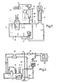
- La figure 3 est un diagramme montrant les périodes de temps sur lesquelles on effectue les calculs de fuite.Figure 3 is a diagram showing the time periods over which the leakage calculations are performed.
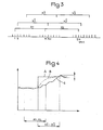
- La figure 4 est un diagramme montrant comparativement les fuites réelles et calculées par la méthode suivant l'invention, pendant le fonctionnement d'un réacteur nucléaire à eau sous pression.FIG. 4 is a diagram showing comparatively the actual leaks calculated by the method according to the invention, during the operation of a pressurized water nuclear reactor.
Sur la figure 1, on voit une boucle d'un circuit primaire d'un réacteur nucléaire à eau sous pression. Le réacteur nucléaire comporte une cuve 1 renfermant le coeur 2 du réacteur et reliée par des canalisations 3 et 4 à un générateur de vapeur 6 et à une pompe primaire 7 permettant la mise en circulation de l'eau sous pression à l'intérieur des canalisations 3 et 4 suivant la direction des flèches 8.In Figure 1, we see a loop of a primary circuit of a pressurized water nuclear reactor. The nuclear reactor includes a
La canalisation 3 recevant l'eau sous pression à haute température sortant du coeur constitue la branche chaude du réacteur alors que la conduite 4, assurant le retour de l'eau sous pression à la cuve 1, après son passage dans le générateur de vapeur 6, constitue la branche froide du circuit primaire.The pipe 3 receiving the pressurized water at high temperature leaving the core constitutes the hot branch of the reactor while the
Le générateur de vapeur 6 comporte un faisceau 9 à l'intérieur duquel circule l'eau sous pression pour l'échauffement de l'eau d'alimentation du générateur de vapeur qui est échauffée puis vaporisée avant d'être envoyée à la turbine de la centrale nucléaire.The
Sur la figure 1 on a représenté la boucle du circuit primaire sur laquelle se trouve le pressuriseur 10 qui assure la régulation de pression dans le circuit primaire. Pour celà des éléments de chauffage électrique 11 pénètrent par la partie inférieure du pressuriseur. Une aspersion auxiliaire 12 et un dispositif de décharge 13 du pressuriseur permettent de ramener l'eau à sa pression nominale en cas de dépassement.In Figure 1 there is shown the loop of the primary circuit on which is the
Sur la figure 2, on voit le circuit de contrôle volumétrique et chimique (RCV) du réacteur nucléaire branché en dérivation sur une des boucles de ce réacteur identique à la boucle représentée sur la figure 1.In FIG. 2, we see the volumetric and chemical control circuit (RCV) of the nuclear reactor connected in diversion to one of the loops of this reactor identical to the loop shown in FIG. 1.
Une partie du circuit de contrôle volumétrique et chimique se trouve à l'extérieur du bâtiment de sécurité du réacteur 14, la partie disposée à l'intérieur du bâtiment de sécurité 14 comportant un échangeur de chaleur 15 pour refroidir et dépressuriser le fluide primaire avant sa sortie du bâtiment 14.A part of the volumetric and chemical control circuit is located outside the safety building of the
Le circuit RCV comporte, à l'extérieur du bâtiment 14, des échangeurs de chaleur refroidisseurs 16, un réservoir d'appoint 17 et des unités de déminéralisation 18. Une pompe de charge 19 permet de faire circuler le fluide à l'intérieur du circuit RCV.The RCV circuit comprises, outside the
Un ensemble de vannes permet d'isoler le circuit RCV du circuit primaire, lorsqu'il n'est pas en service.A set of valves is used to isolate the RCV circuit from the primary circuit, when it is not in service.
Pour la mise en oeuvre du procédé suivant l'invention, il est nécessaire de déterminer, pour tout le volume interne du circuit primaire à l'exception des réservoirs qui se trouvent sur celui-ci, un découpage en volumes élémentaires choisis de façon qu'à l'intérieur de ces volumes élémentaires, la température et la pression soient suffisamment uniformes pour que les calculs de masses d'eau ultérieurs soient significatifs. En réalité, les volumes élémentaires sont choisis de façon que la température et la pression soient égales en tout point du volume élémentaire, compte tenu d'une marge d'erreur acceptable prédéterminée qui permet d'effectuer des calculs de masse d'eau avec une erreur maximum acceptable.For the implementation of the method according to the invention, it is necessary to determine, for the entire internal volume of the primary circuit with the exception of the reservoirs which are thereon, a breakdown into elementary volumes chosen so that inside these elementary volumes, the temperature and the pressure are sufficiently uniform so that the calculations of subsequent water masses are significant. In reality tee, the elementary volumes are chosen so that the temperature and the pressure are equal at all points of the elementary volume, taking into account a predetermined acceptable margin of error which makes it possible to carry out water mass calculations with an error maximum acceptable.
La connaissance de la répartition des température et pression dans le circuit primaire d'un réacteur à eau sous pression, par exemple un réacteur nucléaire à trois boucles de puissance électrique 900 MW a permis de déterminer dix-neuf volumes élémentaires à l'intérieur du circuit primaire, à l'intérieur desquels la température et la pression restent suffisamment homogènes et constantes au cours du fonctionnement du réacteur. On prend en compte également les trois réservoirs en communication avec le circuit primaire, à savoir le réservoir de décharge du pressuriseur 20 (figure 1), le réservoir de recueil des fuites localisées du circuit primaire et le réservoir de stockage pour le traitement des effluents primaires.Knowledge of the distribution of temperature and pressure in the primary circuit of a pressurized water reactor, for example a nuclear reactor with three loops of 900 MW electrical power, made it possible to determine nineteen elementary volumes inside the circuit primary, within which the temperature and pressure remain sufficiently homogeneous and constant during the operation of the reactor. The three tanks in communication with the primary circuit are also taken into account, namely the
En ce qui concerne le circuit auxiliaire RCV représenté à la figure 2, on découpe son volume interne en trois volumes élémentaires et l'on prend en compte le réservoir 17 permettant le contrôle volumétrique du circuit primaire.With regard to the RCV auxiliary circuit shown in FIG. 2, its internal volume is divided into three elementary volumes and the
Pour chacun des volumes élémentaires ou réservoirs, on mesure avec une certaine périodicité, pendant le fonctionnement du réacteur, la température et la pression de l'eau dans le volume élémentaire ou réservoir considéré. En ce qui concerne les réservoirs, on mesure de plus le niveau de l'eau dans ce réservoir avec la même périodicité.For each of the elementary volumes or reservoirs, the temperature and the pressure of the water in the elementary volume or reservoir considered are measured with a certain periodicity, during the operation of the reactor. With regard to the reservoirs, the water level in this reservoir is also measured with the same periodicity.
Enfin, on recueille en plus des signaux représentatifs des mesures de niveaux de pression et de température, des signaux décrivant l'étant d'ouverture ou de fermeture des vannes du circuit primaire et du circuit auxiliaire pour connaître les débits éventuels d'eau venant en déduction ou en supplément de la masse d'eau du circuit primaire au moment de la mesure.Finally, in addition to signals representative of the pressure and temperature level measurements, signals describing the opening or closing element of the valves of the primary circuit and of the auxiliary circuit are collected in order to know the possible water flows coming in. deduction or in addition to the mass of water in the primary circuit at the time of measurement.
La mesure des paramètres envisagés ci-dessus permet de calculer les masses d'eau dans les réservoirs et dans les volumes élémentaires du circuit primaire et du circuit auxiliaire au moment de la mesure.The measurement of the parameters envisaged above makes it possible to calculate the bodies of water in the reservoirs and in the elementary volumes of the primary circuit and of the auxiliary circuit at the time of the measurement.
De façon pratique on dispose des capteurs de pression et de température au niveau de chacun des volumes élémentaires et des- -réservoirs ainsi que des capteurs de niveau dans chacun des réservoirs. Ces capteurs envoient les résultats de la mesure sous forme de signaux à une unité centrale de calcul qui effectue la détermination de la masse d'eau en utilisant des tables d'eau mises en mémoire.In practice, there are pressure and temperature sensors at each of the elementary volumes and of the reservoirs as well as level sensors in each of the tanks. These sensors send the results of the measurement in the form of signals to a central computing unit which performs the determination of the mass of water using stored water tables.
Le calcul doit prendre en compte l'eau sous forme liquide et l'eau sous forme de vapeur à l'intérieur de chacun des volumes déterminés.The calculation must take into account water in liquid form and water in the form of vapor inside each of the determined volumes.
Par exemple, dans le cas du pressuriseur, on considère un volume unique à l'intérieur duquel l'eau et la vapeur sous pression sont en équilibre. Le volume en eau comporte le fond du pressuriseur et le volume cylindrique de la colonne d'eau surmontant celui-ci.For example, in the case of the pressurizer, a single volume is considered within which the water and the vapor under pressure are in equilibrium. The water volume includes the bottom of the pressurizer and the cylindrical volume of the water column surmounting it.
Le volume de vapeur dans le pressuriseur comporte le volume cylindrique total du pressuriseur moins le volume correspondant à la colonne d'eau et le volume de la partie supérieure bombée du pressuriseur.The volume of steam in the pressurizer includes the total cylindrical volume of the pressurizer minus the volume corresponding to the water column and the volume of the domed upper part of the pressurizer.
Le niveau dans le pressuriseur est donc mesuré, comme dans le cas des réservoirs, pour le calcul de la masse d'eau.The level in the pressurizer is therefore measured, as in the case of tanks, for the calculation of the mass of water.
Le volume intérieur primaire des générateurs de vapeur est constitué par la somme des volumes intérieurs des tubes du faisceau.The primary interior volume of the steam generators is made up of the sum of the interior volumes of the bundle tubes.
Le volume de chaque branche froide du réacteur est constitué par le volume de la boite à eau du côté de la sortie de l'eau dans le générateur de vapeur, par le volume de la pompe primaire et le volume des canalisations reliant la pompe primaire au générateur de vapeur et à la cuve, le volume des tuyauteries de contournement et le volume des tuyauteries d'aspersion du pressuriseur.The volume of each cold branch of the reactor is constituted by the volume of the water box on the side of the water outlet in the steam generator, by the volume of the primary pump and the volume of the pipes connecting the primary pump to the steam generator and to the tank, the volume of the bypass pipes and the volume of the pressurizer's spray pipes.
En ce qui concerne le circuit de contrôle volumétrique et chimique du réacteur, son volume est faible par rapport au volume du circuit primaire, si bien que les disparités de température dans ce circuit ont une influence faible sur le calcul final de la masse d'eau et du taux de fuite. On choisit donc un découpage en trois volumes élémentaires seulement de ce circuit RCV.As regards the volumetric and chemical control circuit of the reactor, its volume is small compared to the volume of the primary circuit, so that the temperature disparities in this circuit have a weak influence on the final calculation of the water mass and the leak rate. We therefore choose a division into three elementary volumes only of this RCV circuit.
Le principe de détermination de la masse d'eau repose sur le calcul du volume renfermant cette eau en fonction de la pression et de la température mesurée. On obtient le volume élémentaire à la pression P et à la température T de service du réacteur par la formule :
- Vi (PiTi) = Vi froid (1 + i Ti + xi Pi) où
- Vi (PiTi) = volume élémentaire à la pression P et température T de service du réacteur
- Vi froid = volume élémentaire à froid
- αi = coefficient de dilatation du volume élémentaire i
- xi = coefficient de compressibilité pour le volume élémentaire i
- Vi (PiTi) = Vi cold (1 + i Ti + xi Pi) where
- Vi (PiTi) = elementary volume at pressure P and reactor operating temperature T
- Vi cold = elementary volume cold
- αi = coefficient of expansion of the elementary volume i
- xi = compressibility coefficient for the elementary volume i
Les tables d'eau mises en mémoire dans le calculateur permettent de disposer de la masse volumique de l'eau aux pression et température correspondant aux pression et température du volume élémentaire i. La masse d'eau renfermée dans chaque volume élémentaire est donc calculée en multipliant le volume élémentaire Vi (Pi,Ti) par la masse volumique de l'eau à la température T et à la pression P.The water tables stored in the computer make it possible to have the density of the water at pressure and temperature corresponding to the pressure and temperature of the elementary volume i. The mass of water contained in each elementary volume is therefore calculated by multiplying the elementary volume Vi (Pi, Ti) by the density of water at temperature T and at pressure P.
Dans les parties plus complexes comme le coeur du réacteur et les générateurs de vapeur, une modélisation de la température a été faite de fa- ç n à approcher l'intégrale portant sur le volume élémentaire i ∫∫Vi ρ(Ti Pi) dVi par une expression du type Vi (T moy.i, Pi) e (T moy.i, Pi).In more complex parts such as the reactor core and the steam generators, the temperature has been modeled so as to approach the integral relating to the elementary volume i ∫∫Vi ρ (Ti Pi) dVi by an expression of the type Vi (T avg i, Pi) e (T avg i, Pi).
En ce qui concerne les réservoirs et le pressuriseur, on prend en compte le niveau mesuré dans le réservoir pour déterminer le volume d'eau dans celui-ci. On a mis en mémoire dans le calculateur, la relation entre le niveau et le volume renfermé par le réservoir, pour permettre ce calcul.With regard to the tanks and the pressurizer, the level measured in the tank is taken into account to determine the volume of water in it. The relationship between the level and the volume contained by the reservoir has been stored in the calculator to allow this calculation.
La périodicité d'acquisition des différents paramètres, pression, température, niveau, peut être un peu différente et le calcul sera effectué avec une périodicité, ou pas, égale ou un peu supérieure à la périodicité maximum d'acquisition des paramètres mesurés.The periodicity of acquisition of the various parameters, pressure, temperature, level, can be a little different and the calculation will be carried out with a periodicity, or not, equal or a little higher than the maximum periodicity of acquisition of the measured parameters.
Dans le cas d'un réacteur nucléaire à trois boucles envisagé ci-dessus, le pas est de vingt secondes et le calculateur permet de disposer d'une valeur précise des masses d'eau dans chacun des volumes élémentaires et réservoirs toutes les vingt secondes. Le calculateur effectue la somme de ces valeurs élémentaires de la masse d'eau pour connaître la masse d'eau totale instantanée dans le circuit primaire.In the case of a nuclear reactor with three loops envisaged above, the step is twenty seconds and the computer makes it possible to have a precise value of the water masses in each of the elementary volumes and reservoirs every twenty seconds. The computer performs the sum of these elementary values of the water mass to find out the total instantaneous water mass in the primary circuit.
En ce qui concerne la cuve du réacteur, on distingue les volumes élémentaires suivants :
- - Le volume de la cuve côté froid constitué par le volume d'entrée de l'eau venant des branches froides et le volume mort occupé par l'eau avant son passage dans le coeur.
- - Le volume du coeur disponible pour le passage de l'eaù.
- - Le volume de la partie supérieure de la cuve ou plenum.
- - Enfin, les trois volumes correspondant aux branches chaudes et déterminés comme indiqué ci-dessus.
- - The volume of the tank on the cold side consisting of the volume of water entering from the cold branches and the dead volume occupied by the water before it passes through the heart.
- - The volume of the heart available for the passage of water.
- - The volume of the upper part of the tank or plenum.
- - Finally, the three volumes corresponding to the hot branches and determined as indicated above.
Sur la figure 3, on voit le principe de calcul des masses d'eau dans le circuit primaire au cours-du temps.In Figure 3, we can see the principle of calculating the masses of water in the primary circuit over time.
Sur la ligne inférieure du diagramme, on a représenté avec une graduation par pas de vingt secondes l'échelle des temps. Chacune des graduations 1, 2, ... m, m + 1,... représentent l'instant d'acquisition d'une valeur de la masse d'eau dans le circuit primaire.On the bottom line of the diagram, we have represented with a graduation in steps of twenty seconds the timescale. Each of the
Les lignes supérieures du diagramme représentent des périodes de temps Xl, X2, ... représentant un nombre entier de pas de vingt secondes.The upper lines of the diagram represent periods of time Xl, X2, ... representing a whole number of steps of twenty seconds.
On a choisi pour la détermination de la masse d'eau et du taux de fuite du réacteur dans l'exemple mentionné ci-dessus, une période de temps égale à trente minutes c'est-à-dire à quatre-vingt dix pas de vingt secondes.For the determination of the mass of water and the rate of leakage of the reactor, in the example mentioned above, a period of time equal to thirty minutes, that is to say ninety steps of twenty seconds.
Chacune des périodes Xl, X2,... représente donc trente minutes ou quatre-vingt dix pas.Each of the periods Xl, X2, ... therefore represents thirty minutes or ninety steps.
La masse totale moyenne d'eau dans le circuit primaire pendant une période X quelconque de quatre-vingt dix pas est égale à la somme des quatre-vingt dix valeurs de la masse totale déterminée à chacun des pas divisée par quatre-vingt dix.The average total mass of water in the primary circuit during any period X of ninety steps is equal to the sum of the ninety values of the total mass determined at each step divided by ninety.
Ce calcul de la valeur moyenne est effectué non seulement pour les périodes successives de trente minutes Xl, X2,... mais également pour des périodes de même durée décalées d'un pas (X11., X12,...) ou d'un nombre quelconque de pas (Xnl, Xn2, ...) et inférieur à quatre-vingt dix.This calculation of the average value is carried out not only for successive periods of thirty minutes Xl, X2, ... but also for periods of the same duration shifted by one step (X1 1. , X1 2 , ...) or any number of steps (Xn l , Xn 2 , ...) and less than ninety.
On détermine ainsi des couples de valeurs moyennes sur des périodes Xl X2, Xll X12, Xnl Xn2, successives et d'une durée fixe de trente minutes.Couples of average values are thus determined over successive periods Xl X2, Xl l X1 2 , Xnl Xn 2 and a fixed duration of thirty minutes.
Le calculateur détermine la différence entre ces valeurs moyennes au cours de deux périodes successives de trente minutes, ce qui donne une valeur du débit de fuite à un instant donné caractérisé par un certain nombre de pas.The computer determines the difference between these average values during two successive periods of thirty minutes, which gives a value of the leakage rate at a given instant characterized by a certain number of steps.
La valeur du débit de fuite au pas suivant sera déterminée par la différence des valeurs moyennes calculées sur des périodes décalées d'un pas par rapport aux périodes précédentes (X11 et X12).The value of the leakage rate at the next step will be determined by the difference of the average values calculated over periods shifted by one step compared to the previous periods (X1 1 and X12).
A chaque pas on calculera donc une valeur du débit de fuite égale à la différence entre les valeurs moyennes des masses d'eau dans le circuit primaire calculées sur deux périodes successives de quatre-vingt dix pas.At each step, therefore, a value of the leakage rate will be calculated equal to the difference between the average values of the bodies of water in the primary circuit calculated over two successive periods of ninety steps.
Sur la figure 4 on a représenté, dans le cas d'une variation brusque représentée de façon théorique par la courbe A, la courbe C correspondant aux valeurs du débit de fuite obtenu par le procédé suivant l'invention.In FIG. 4 is shown, in the case of an abrupt variation represented theoretically by curve A, curve C corresponding to the values of the leakage rate obtained by the process according to the invention.
On voit que la valeur calculée du débit de fuite augmente d'une façon progressive jusqu'au moment où elle s'équilibre à une valeur oscillant autour de la nouvelle valeur théorique du débit de fuite. En effet, les résultats du calcul tiennent compte des valeurs de la masse sur des périodes antérieures à la variation brusque du taux de fuite.It can be seen that the calculated value of the leakage rate increases progressively until it equilibrates to a value oscillating around the new theoretical value of the leakage rate. In fact, the results of the calculation take into account the values of the mass over periods prior to the sudden change in the leak rate.
Lorsque les fuites sont établies à leur nouvelle valeur, on con- nait cependant le niveau du débit de fuite avec une très bonne précision qui est de l'ordre de quelques litres par heure dans le cas de l'application à un réacteur nucléaire à trois boucles envisagée ci-dessus qui fonctionne en régime stable avec un débit de fuites moyen de l'ordre de 100 1/hWhen the leaks are established at their new value, however, the level of leakage rate is born with very good precision which is of the order of a few liters per hour in the case of the application to a nuclear reactor with three loops envisaged above which operates in stable regime with a rate average leakage of around 100 1 / h
En fait, la variation réelle des fuites ne suit jamais une courbe théorique telle que représentée en A sur la figure 4 mais plutôt une variation telle que représentée en B, progressive au cours du temps.In fact, the real variation of the leaks never follows a theoretical curve as represented in A in FIG. 4 but rather a variation as represented in B, progressive over time.
On voit donc que le procédé suivant l'invention permet de calculer avec une très bonne précision le débit de fuite total du circuit primaire du réacteur sans avoir recours à d'autres mesures que des mesures de niveau, de température et de pression dans ce circuit.It can therefore be seen that the method according to the invention makes it possible to calculate with very good precision the total leakage rate of the primary circuit of the reactor without having recourse to other measurements than level, temperature and pressure measurements in this circuit .
La valeur des fuites non contrôlées peut être obtenue en retranchant de la valeur des fuites totales, la valeur moyenne des fuites contrôlées sur la période correspondant au calcul des fuites totales.The value of uncontrolled leaks can be obtained by subtracting from the value of total leaks, the average value of controlled leaks over the period corresponding to the calculation of total leaks.
Il est bien évident que l'invention ne se limite pas au mode de réalisation qui vient d'être décrit mais qu'elle en comporte au contraire toutes les variantes.It is obvious that the invention is not limited to the embodiment which has just been described but that, on the contrary, it includes all of its variants.
C'est ainsi que le découpage du circuit primaire et la finesse de la modélisation peut être réalisé d'une façon différente de celle qui a été décrite, en fonction des caractéristiques de ce circuit primaire et de la variation de la température et de la pression de l'eau dans ces différentes parties.Thus the cutting of the primary circuit and the finesse of the modeling can be carried out in a different way from that which has been described, depending on the characteristics of this primary circuit and the variation of the temperature and the pressure. water in these different parts.
De la même façon, étant donnée une périodicité d'acquisition des données nécessaires au calcul de la masse d'eau, il est possible de constituer des périodes pour le calcul de la moyenne de cette masse d'eau correspondant à un nombre de pas quelconque d'acquisition des données.In the same way, given a periodicity of acquisition of the data necessary for the calculation of the body of water, it is possible to constitute periods for the calculation of the average of this body of water corresponding to any number of steps data acquisition.
Cependant, la période de calcul de la valeur moyenne ne doit pas descendre en-dessous d'une certaine valeur pour que l'évaluation du débit de fuite soit faite avec une précision suffisante.However, the period of calculation of the average value must not fall below a certain value for the evaluation of the leakage rate to be made with sufficient precision.
Dans le cas d'un réacteur nucléaire à trois boucles et d'un mode de découpage et de calcul tels que décrits ci-dessus, il est nécessaire de choisir une période de temps M supérieure à dix minutes.In the case of a nuclear reactor with three loops and a chopping and calculation mode as described above, it is necessary to choose a time period M greater than ten minutes.
L'invention s'applique à tout type de circuit primaire d'un réacteur nucléaire à eau sous pression auquel est associé un ou plusieurs circuits auxiliaires tels qu'un circuit de contrôle volumétrique et chimique.The invention applies to any type of primary circuit of a pressurized water nuclear reactor with which one or more auxiliary circuits is associated such as a volumetric and chemical control circuit.
Claims (2)
et que, sur des périodes de temps correspondant à un multiple du pas et décalées dans le temps d'au moins un pas, on calcule la moyenne des masses d'eau du circuit primaire et la différence des valeurs moyennes correspondant à deux périodes de temps successives, représentative du débit de fuite du circuit primaire.1.- Method for controlling leaks in the primary circuit of a pressurized water nuclear reactor comprising a tank (1) enclosing the core (2) of the reactor, at least two steam generators (6) connected to the tank so independent by pipes (3, 4) for circulation of pressurized water, a pressurizer (10), at least one auxiliary circuit for controlling and adding pressure water and reservoirs (20, 17) interposed on the primary circuit and the auxiliary circuit, characterized by the fact:
and that, over time periods corresponding to a multiple of the step and shifted in time by at least one step, the average of the water bodies of the primary circuit is calculated and the difference of the average values corresponding to two time periods successive, representative of the leakage flow of the primary circuit.
Applications Claiming Priority (2)
| Application Number | Priority Date | Filing Date | Title |
|---|---|---|---|
| FR8314509A FR2551906B1 (en) | 1983-09-13 | 1983-09-13 | METHOD FOR CONTROLLING LEAKS FROM THE PRIMARY CIRCUIT OF A PRESSURE WATER NUCLEAR REACTOR |
| FR8314509 | 1983-09-13 |
Publications (2)
| Publication Number | Publication Date |
|---|---|
| EP0139559A1 true EP0139559A1 (en) | 1985-05-02 |
| EP0139559B1 EP0139559B1 (en) | 1987-06-10 |
Family
ID=9292143
Family Applications (1)
| Application Number | Title | Priority Date | Filing Date |
|---|---|---|---|
| EP84401789A Expired EP0139559B1 (en) | 1983-09-13 | 1984-09-11 | System for determining leakage of a pwr |
Country Status (9)
| Country | Link |
|---|---|
| US (1) | US4650635A (en) |
| EP (1) | EP0139559B1 (en) |
| JP (1) | JPS6086490A (en) |
| KR (1) | KR910002338B1 (en) |
| CA (1) | CA1216378A (en) |
| DE (1) | DE3464175D1 (en) |
| ES (1) | ES8702052A1 (en) |
| FR (1) | FR2551906B1 (en) |
| ZA (1) | ZA846747B (en) |
Families Citing this family (7)
| Publication number | Priority date | Publication date | Assignee | Title |
|---|---|---|---|---|
| DE19612947C1 (en) * | 1996-04-01 | 1997-09-11 | Siemens Ag | Leak detection device and method |
| US8953731B2 (en) | 2004-12-03 | 2015-02-10 | General Electric Company | Method of producing isotopes in power nuclear reactors |
| US9899107B2 (en) | 2010-09-10 | 2018-02-20 | Ge-Hitachi Nuclear Energy Americas Llc | Rod assembly for nuclear reactors |
| CN111680257B (en) * | 2020-06-16 | 2023-09-08 | 三门核电有限公司 | Method for calculating leakage rate of steam generator during heat test of nuclear power plant |
| CN113303305B (en) * | 2021-05-14 | 2022-02-11 | 北京百瑞盛田环保科技发展有限公司 | Pesticide application monitoring method, device and system |
| CN114038592B (en) * | 2021-10-12 | 2024-03-15 | 中广核陆丰核电有限公司 | Nuclear power plant primary loop leakage rate monitoring method and device |
| CN115662665B (en) * | 2022-09-09 | 2024-01-30 | 中国核动力研究设计院 | Method and system for monitoring leakage of pressurized container of pressurized water nuclear reactor |
Citations (3)
| Publication number | Priority date | Publication date | Assignee | Title |
|---|---|---|---|---|
| US3644172A (en) * | 1968-09-23 | 1972-02-22 | Westinghouse Electric Corp | System for determining leakage inside a reactor containment |
| US3712850A (en) * | 1969-08-08 | 1973-01-23 | Westinghouse Electric Corp | Method for determining reactor coolant system leakage |
| FR2214992A1 (en) * | 1973-01-24 | 1974-08-19 | Siemens Ag |
Family Cites Families (3)
| Publication number | Priority date | Publication date | Assignee | Title |
|---|---|---|---|---|
| US3155595A (en) * | 1959-12-04 | 1964-11-03 | Babcock & Wilcox Co | Preheating and cooling a nuclear reactor system |
| US3699802A (en) * | 1971-02-17 | 1972-10-24 | Takeshi Hotta | Condenser leakage monitoring system |
| FR2522153A1 (en) * | 1982-02-19 | 1983-08-26 | Framatome Sa | ULTRASONIC MEASUREMENT METHOD FOR THE VOLUME OF GAS PRESENT IN AN ENCLOSURE COMPRISING A LIQUID-GAS MIXTURE AT THE TOTAL VOLUME OF THE ENCLOSURE |
-
1983
- 1983-09-13 FR FR8314509A patent/FR2551906B1/en not_active Expired
-
1984
- 1984-08-29 ZA ZA846747A patent/ZA846747B/en unknown
- 1984-09-11 EP EP84401789A patent/EP0139559B1/en not_active Expired
- 1984-09-11 DE DE8484401789T patent/DE3464175D1/en not_active Expired
- 1984-09-12 CA CA000463010A patent/CA1216378A/en not_active Expired
- 1984-09-12 KR KR1019840005555A patent/KR910002338B1/en not_active IP Right Cessation
- 1984-09-12 ES ES535845A patent/ES8702052A1/en not_active Expired
- 1984-09-13 JP JP59192433A patent/JPS6086490A/en active Granted
- 1984-09-13 US US06/650,382 patent/US4650635A/en not_active Expired - Fee Related
Patent Citations (3)
| Publication number | Priority date | Publication date | Assignee | Title |
|---|---|---|---|---|
| US3644172A (en) * | 1968-09-23 | 1972-02-22 | Westinghouse Electric Corp | System for determining leakage inside a reactor containment |
| US3712850A (en) * | 1969-08-08 | 1973-01-23 | Westinghouse Electric Corp | Method for determining reactor coolant system leakage |
| FR2214992A1 (en) * | 1973-01-24 | 1974-08-19 | Siemens Ag |
Also Published As
| Publication number | Publication date |
|---|---|
| KR850002311A (en) | 1985-05-10 |
| DE3464175D1 (en) | 1987-07-16 |
| EP0139559B1 (en) | 1987-06-10 |
| US4650635A (en) | 1987-03-17 |
| ES8702052A1 (en) | 1986-12-01 |
| ES535845A0 (en) | 1986-12-01 |
| KR910002338B1 (en) | 1991-04-20 |
| ZA846747B (en) | 1985-05-29 |
| JPS6086490A (en) | 1985-05-16 |
| JPH0511277B2 (en) | 1993-02-15 |
| FR2551906A1 (en) | 1985-03-15 |
| FR2551906B1 (en) | 1986-03-14 |
| CA1216378A (en) | 1987-01-06 |
Similar Documents
| Publication | Publication Date | Title |
|---|---|---|
| EP0243049B1 (en) | Two and three dimensional core power distribution monitor and display | |
| EP0139559B1 (en) | System for determining leakage of a pwr | |
| FR2472738A1 (en) | WATER LEVEL INDICATOR FOR NUCLEAR REACTOR | |
| EP0010036B1 (en) | Operating process for a light-water cooled nuclear reactor | |
| EP0087365B1 (en) | Method for the ultrasonic measuring of the relationship between the volume of gas present in an enclosure containing a liquid-gas mixture end the total volume of the enclosure | |
| CN108956089A (en) | A kind of tank leak Flash tank behavioral trait experiment test device and method | |
| FR2529706A1 (en) | METHOD FOR CONTROLLING THE OPERATION OF AN ELECTRICITY GENERATOR OPERATING WITH NUCLEAR ENERGY AND FOR INTERFACING BETWEEN THIS GENERATOR AND A DISTRIBUTION NETWORK | |
| EP0094884B1 (en) | Method and device for controlling the ph of the cooling water of a pressurized water nuclear reactor | |
| EP0122172B1 (en) | Device for fast and accurate power determination of a pressurised water nuclear reactor | |
| CN208283037U (en) | A kind of tank leak Flash tank behavioral trait experiment test device | |
| CN110530660A (en) | A kind of slot type photo-thermal power station loop performance detection system and its detection method | |
| EP0126692B1 (en) | Method and device for detecting reactivity variations in a pwr's core | |
| FR2510750A1 (en) | Fuel gauging system for vehicle fuel tank - uses volume of gas under pressure injected into tank to determn. fuel contents by measuring pressure difference | |
| Caramello et al. | Thermal hydraulic analysis of Alfred bayonet tube steam generator | |
| Rice et al. | Extended development of a sodium hydroxide thermal energy storage module | |
| FR2565324A1 (en) | CONTROL SYSTEM FOR A FLUID HEATED STEAM GENERATOR | |
| Volkov et al. | Experimental and calculated studies of condensation-induced water hammer | |
| CN209858233U (en) | Slot type light and heat power station return circuit performance detecting system | |
| FR2576100A1 (en) | METHOD FOR DETECTING MEDIUM OR LARGE LEAKS THROUGH THE EXCHANGE WALL OF A STEAM GENERATOR USING LIQUID METAL | |
| EP0184507B1 (en) | Process and apparatus for the pretreatment of liquid sodium containing dissolved impurities | |
| EP0113670B1 (en) | Method of detecting breakage in nuclear reactor | |
| WO2023105165A1 (en) | Method for maintaining a steam generator involving a model | |
| FR3125628A1 (en) | Process and installation for the destruction of radioactive sodium | |
| FR3119701A1 (en) | Process and installation for the destruction of radioactive sodium | |
| EP0408725A1 (en) | Auxiliary volumetric and chemical controlling circuit for the primary circuit of a pressurized water nuclear reactor |
Legal Events
| Date | Code | Title | Description |
|---|---|---|---|
| PUAI | Public reference made under article 153(3) epc to a published international application that has entered the european phase |
Free format text: ORIGINAL CODE: 0009012 |
|
| AK | Designated contracting states |
Designated state(s): BE CH DE GB IT LI SE |
|
| 17P | Request for examination filed |
Effective date: 19850426 |
|
| 17Q | First examination report despatched |
Effective date: 19860818 |
|
| GRAA | (expected) grant |
Free format text: ORIGINAL CODE: 0009210 |
|
| AK | Designated contracting states |
Kind code of ref document: B1 Designated state(s): BE CH DE GB IT LI SE |
|
| ITF | It: translation for a ep patent filed |
Owner name: JACOBACCI & PERANI S.P.A. |
|
| REF | Corresponds to: |
Ref document number: 3464175 Country of ref document: DE Date of ref document: 19870716 |
|
| PLBE | No opposition filed within time limit |
Free format text: ORIGINAL CODE: 0009261 |
|
| STAA | Information on the status of an ep patent application or granted ep patent |
Free format text: STATUS: NO OPPOSITION FILED WITHIN TIME LIMIT |
|
| 26N | No opposition filed | ||
| ITTA | It: last paid annual fee | ||
| EAL | Se: european patent in force in sweden |
Ref document number: 84401789.7 |
|
| PGFP | Annual fee paid to national office [announced via postgrant information from national office to epo] |
Ref country code: CH Payment date: 19960819 Year of fee payment: 13 |
|
| PGFP | Annual fee paid to national office [announced via postgrant information from national office to epo] |
Ref country code: DE Payment date: 19960821 Year of fee payment: 13 |
|
| PGFP | Annual fee paid to national office [announced via postgrant information from national office to epo] |
Ref country code: GB Payment date: 19960903 Year of fee payment: 13 |
|
| PGFP | Annual fee paid to national office [announced via postgrant information from national office to epo] |
Ref country code: SE Payment date: 19960920 Year of fee payment: 13 |
|
| PGFP | Annual fee paid to national office [announced via postgrant information from national office to epo] |
Ref country code: BE Payment date: 19960925 Year of fee payment: 13 |
|
| PG25 | Lapsed in a contracting state [announced via postgrant information from national office to epo] |
Ref country code: GB Free format text: LAPSE BECAUSE OF NON-PAYMENT OF DUE FEES Effective date: 19970911 |
|
| PG25 | Lapsed in a contracting state [announced via postgrant information from national office to epo] |
Ref country code: SE Free format text: LAPSE BECAUSE OF NON-PAYMENT OF DUE FEES Effective date: 19970912 |
|
| PG25 | Lapsed in a contracting state [announced via postgrant information from national office to epo] |
Ref country code: LI Free format text: LAPSE BECAUSE OF NON-PAYMENT OF DUE FEES Effective date: 19970930 Ref country code: CH Free format text: LAPSE BECAUSE OF NON-PAYMENT OF DUE FEES Effective date: 19970930 Ref country code: BE Free format text: LAPSE BECAUSE OF NON-PAYMENT OF DUE FEES Effective date: 19970930 |
|
| BERE | Be: lapsed |
Owner name: FRAMATOME ET CIE Effective date: 19970930 |
|
| GBPC | Gb: european patent ceased through non-payment of renewal fee |
Effective date: 19970911 |
|
| REG | Reference to a national code |
Ref country code: CH Ref legal event code: PL |
|
| PG25 | Lapsed in a contracting state [announced via postgrant information from national office to epo] |
Ref country code: DE Free format text: LAPSE BECAUSE OF NON-PAYMENT OF DUE FEES Effective date: 19980603 |
|
| EUG | Se: european patent has lapsed |
Ref document number: 84401789.7 |