EP0139397A2 - Abdichtungsvorrichtungen drehender Wellen - Google Patents
Abdichtungsvorrichtungen drehender Wellen Download PDFInfo
- Publication number
- EP0139397A2 EP0139397A2 EP84305749A EP84305749A EP0139397A2 EP 0139397 A2 EP0139397 A2 EP 0139397A2 EP 84305749 A EP84305749 A EP 84305749A EP 84305749 A EP84305749 A EP 84305749A EP 0139397 A2 EP0139397 A2 EP 0139397A2
- Authority
- EP
- European Patent Office
- Prior art keywords
- ring
- shaft
- housing
- sealing
- sealing arrangement
- Prior art date
- Legal status (The legal status is an assumption and is not a legal conclusion. Google has not performed a legal analysis and makes no representation as to the accuracy of the status listed.)
- Withdrawn
Links
- 238000007789 sealing Methods 0.000 title claims abstract description 23
- 229920001343 polytetrafluoroethylene Polymers 0.000 claims abstract description 5
- 239000004810 polytetrafluoroethylene Substances 0.000 claims abstract description 5
- -1 polytetrafluoroethylene Polymers 0.000 claims abstract description 3
- 239000000463 material Substances 0.000 claims description 5
- 239000004033 plastic Substances 0.000 claims description 2
- 229920003023 plastic Polymers 0.000 claims description 2
- 230000002093 peripheral effect Effects 0.000 abstract description 2
- 239000012530 fluid Substances 0.000 description 2
- 238000000034 method Methods 0.000 description 2
- 238000003780 insertion Methods 0.000 description 1
- 230000037431 insertion Effects 0.000 description 1
- 238000009434 installation Methods 0.000 description 1
- 230000001473 noxious effect Effects 0.000 description 1
Images

Classifications
-
- F—MECHANICAL ENGINEERING; LIGHTING; HEATING; WEAPONS; BLASTING
- F16—ENGINEERING ELEMENTS AND UNITS; GENERAL MEASURES FOR PRODUCING AND MAINTAINING EFFECTIVE FUNCTIONING OF MACHINES OR INSTALLATIONS; THERMAL INSULATION IN GENERAL
- F16J—PISTONS; CYLINDERS; SEALINGS
- F16J15/00—Sealings
- F16J15/16—Sealings between relatively-moving surfaces
- F16J15/32—Sealings between relatively-moving surfaces with elastic sealings, e.g. O-rings
Definitions
- This invention relates to shaft sealing arrangements and has a particularly useful but not exclusive application in pumps incorporating a rod or shaft which must be sealed to prevent the escape of dangerous or noxious fluids being pumped.
- a shaft sealing arrangement comprising a shaft mounted for axial and/or rotational movement in a surrounding housing, and a sealing ring of non circular cross-section located in an annular groove in either the shaft or the surface of the housing radially facing the shaft and forming a seal with a radially facing surface of the housing or the shaft as the case may be, which ring has been toroidally rotated so as to be in a state of strain beyond its instantaneous elastic limit.
- Annular articles made from certain plastics materials are relatively easily strained beyond their instantaneous elastic limit, i.e. when released will not return to their original shape but take up a new stable shape. However, in their over-strained condition and new shape the articles may retain useful properties of resilience.
- plastics materials notably polytetrafluoroethylene (PTFE)
- PTFE polytetrafluoroethylene
- a shaft- sealing arrangement is shown which is intended for use in a double diaphragm pump such as is described in our Patent Application No. 8309426.
- the shaft 10 is reciprocated in its housing 11 and in order to prevent leakage of pumped fluid along the shaft from right to left, a sealing arrangement is provided comprising a sealing ring 12 disposed in a peripheral groove in the housing and engaging the surface of the shaft.
- the sealing ring is in a condition which results from applying toroidal rotation to the ring sufficient to exceed its instantaneous elastic limit.
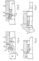
- the sealing ring as originally formed is shown in Figure 1.
- the ring is made from PTFE and has an axially-extending slot 13 formed therein.
- Toroidal rotation is applied to the ring in the direction indicated by the arrow 14 such that the strains in the material exceed the elastic limit of the material, and the material subsequently relaxes into the new but stable condition of equilibrium illustrated in Figure 2.
- the ring shown in Figure 2 is forced into a counterbore 15 in the housing and a rib 16 in the groove engages in the slot 13 in the ring to locate the ring against disengagement axially from the groove.
- the shaft 10 is then pressed through the central aperture of the ring.
- the ring On insertion of the shaft the ring is subjected to further resilient deformation. the ring being rotated into the attitude in which it is shown in Figure 3 but seeking to return to its shape as shown in Figure 2 and thus pressing diagonally opposite corner portions 17, 18 areas of the ring into sealing engagement with the shaft and the wall of the counterbore 15 respectively.
- Figures 4 to 7 illustrate one method and apparatus by which the ring 12 is subjected to toroidal rotation to over-strain it and by which at the same time the ring is positioned in the counterbore 15 in the housing.
- the apparatus comprises a mandrel 25, two annular forming tools 26, 27, and a locating ring 28 which serves to guide the mandrel coaxially within the forming tools 26 and 27.
- An annular tongue 34 on one end of tool 27 has radial dimensions equal to those of the rib in the groove in the housing and registers in a rebate in the adjacent end of tool 26 to locate the latter.
- the mandrel has three portions 30, 31, 32 of differing diameters, and the ring in its original form fits on to the end portion 32, but a groove 33 which has an inclined bottom wall and which is axially shorter than the ring is formed between the two portions 31, 32.
- Locating ring 28 is a sliding fit on end portion 32 of the mandrel, and forming tools 26 and 27 are a sliding fit over locating ring 28 and portion 30, with an internal diameter equal to that of the rib 16 in the groove in the housing.
- the diameter of the middle portion 31 is substantially equal to that of the shaft.
- the forming tool 26 has over one end portion 35 thereof an internal diameter enabling it to accommodate the outer diameter of the ring 12 and has a convexly curved internal surface 36 extending from portion 35 to the other axial end of the tool.
- the sealing ring is first placed on end portion 32 as shown in Figure 4, so that the groove 33 underlies part of the length of the ring and so that the outer diameter of the ring is accommodated in the end portion 35 of tool 26.
- Mandrel 25 is now moved rightward guided by ring 28, as a result of which the ring is subjected to toroidal rotation by the shoulder 37 between portions 31 and 32 of the mandrel and the shoulder between the portions 35 and 36 of the tool 26.
- the ring is rotated into the groove 33 as shown in Figure 5 and then on to the middle portion 31 of the mandrel as shown in Figure 6, so that the ring has undergone 90° of toroidal rotation.
Landscapes
- Engineering & Computer Science (AREA)
- General Engineering & Computer Science (AREA)
- Mechanical Engineering (AREA)
- Sealing Devices (AREA)
Applications Claiming Priority (2)
| Application Number | Priority Date | Filing Date | Title |
|---|---|---|---|
| GB838322844A GB8322844D0 (en) | 1983-08-25 | 1983-08-25 | Shaft sealing arrangements |
| GB8322844 | 1983-08-25 |
Publications (1)
| Publication Number | Publication Date |
|---|---|
| EP0139397A2 true EP0139397A2 (de) | 1985-05-02 |
Family
ID=10547845
Family Applications (1)
| Application Number | Title | Priority Date | Filing Date |
|---|---|---|---|
| EP84305749A Withdrawn EP0139397A2 (de) | 1983-08-25 | 1984-08-22 | Abdichtungsvorrichtungen drehender Wellen |
Country Status (4)
| Country | Link |
|---|---|
| EP (1) | EP0139397A2 (de) |
| JP (1) | JPS60101363A (de) |
| AU (1) | AU3238284A (de) |
| GB (1) | GB8322844D0 (de) |
Cited By (2)
| Publication number | Priority date | Publication date | Assignee | Title |
|---|---|---|---|---|
| EP0403674A1 (de) * | 1987-04-23 | 1990-12-27 | Vfp Corporation | Dichtung |
| GB2264541A (en) * | 1992-02-29 | 1993-09-01 | Rolls Royce Plc | Improved sealing ring for gas turbine engines |
-
1983
- 1983-08-25 GB GB838322844A patent/GB8322844D0/en active Pending
-
1984
- 1984-08-22 EP EP84305749A patent/EP0139397A2/de not_active Withdrawn
- 1984-08-24 JP JP59176511A patent/JPS60101363A/ja active Pending
- 1984-08-24 AU AU32382/84A patent/AU3238284A/en not_active Abandoned
Cited By (3)
| Publication number | Priority date | Publication date | Assignee | Title |
|---|---|---|---|---|
| EP0403674A1 (de) * | 1987-04-23 | 1990-12-27 | Vfp Corporation | Dichtung |
| GB2264541A (en) * | 1992-02-29 | 1993-09-01 | Rolls Royce Plc | Improved sealing ring for gas turbine engines |
| US5344162A (en) * | 1992-02-29 | 1994-09-06 | Rolls-Royce Plc | Sealing ring for gas turbine engines |
Also Published As
| Publication number | Publication date |
|---|---|
| JPS60101363A (ja) | 1985-06-05 |
| AU3238284A (en) | 1985-02-28 |
| GB8322844D0 (en) | 1983-09-28 |
Similar Documents
| Publication | Publication Date | Title |
|---|---|---|
| US4415165A (en) | Integral elastomeric/graphite dynamic face seal | |
| US6050572A (en) | Rotary cartridge seals with retainer | |
| EP0646738B1 (de) | Fluid-Abdichtmittel | |
| US4415167A (en) | Assembled multi-component seal | |
| KR950003001B1 (ko) | 유압식 밀봉 조립체 | |
| KR890701936A (ko) | 센터링 수단을 갖는 메카니칼 실(seal) | |
| EP0385635A2 (de) | Dichtungen | |
| EP0356619A3 (en) | Axial face seal | |
| CA1337872C (en) | Universal seal cage lantern ring with double sided slotted land structure | |
| JP2022522947A (ja) | 回転ジョイント | |
| KR840006515A (ko) | 축봉(shaft seal)시스템 및 방법 | |
| US2729478A (en) | Packing construction | |
| US4155559A (en) | Deformable seal for rotary mechanism | |
| CN112096871A (zh) | 自紧式密封件 | |
| JPH0665910B2 (ja) | 環状ギャップを密封する液圧密封装置 | |
| EP0139397A2 (de) | Abdichtungsvorrichtungen drehender Wellen | |
| US3717293A (en) | Seal assembly | |
| US3751046A (en) | Face type sealing device | |
| US2859988A (en) | Rotary mechanical seal | |
| US2752177A (en) | Fluid seal | |
| JPH0645098Y2 (ja) | リップ型シール | |
| US6454269B2 (en) | Mechanical device with sealing means and method for mounting the sealing means | |
| US3162452A (en) | Hydraulically balanced rotary mechanical seal with double sealing wedges | |
| US3495842A (en) | Low friction rotary shaft bearing seal | |
| GB2044862A (en) | Mechanical seal for preventing fluid leakage |
Legal Events
| Date | Code | Title | Description |
|---|---|---|---|
| PUAI | Public reference made under article 153(3) epc to a published international application that has entered the european phase |
Free format text: ORIGINAL CODE: 0009012 |
|
| AK | Designated contracting states |
Designated state(s): AT BE CH DE FR GB IT LI LU NL SE |
|
| STAA | Information on the status of an ep patent application or granted ep patent |
Free format text: STATUS: THE APPLICATION IS DEEMED TO BE WITHDRAWN |
|
| 18D | Application deemed to be withdrawn |
Effective date: 19870302 |
|
| RIN1 | Information on inventor provided before grant (corrected) |
Inventor name: MELVILLE, JOHN GREGORY EMM |