EP0139381A2 - Ring seal - Google Patents
Ring seal Download PDFInfo
- Publication number
- EP0139381A2 EP0139381A2 EP84305561A EP84305561A EP0139381A2 EP 0139381 A2 EP0139381 A2 EP 0139381A2 EP 84305561 A EP84305561 A EP 84305561A EP 84305561 A EP84305561 A EP 84305561A EP 0139381 A2 EP0139381 A2 EP 0139381A2
- Authority
- EP
- European Patent Office
- Prior art keywords
- ring
- seal
- support
- designated area
- seal according
- Prior art date
- Legal status (The legal status is an assumption and is not a legal conclusion. Google has not performed a legal analysis and makes no representation as to the accuracy of the status listed.)
- Withdrawn
Links
- 238000011109 contamination Methods 0.000 claims abstract description 7
- 238000007789 sealing Methods 0.000 claims description 5
- 230000000717 retained effect Effects 0.000 abstract 1
- 238000009434 installation Methods 0.000 description 5
- 239000004519 grease Substances 0.000 description 4
- 230000008901 benefit Effects 0.000 description 2
- 239000000428 dust Substances 0.000 description 2
- 238000012423 maintenance Methods 0.000 description 2
- 238000004519 manufacturing process Methods 0.000 description 2
- 239000000463 material Substances 0.000 description 2
- 229910000831 Steel Inorganic materials 0.000 description 1
- 239000013536 elastomeric material Substances 0.000 description 1
- 230000007613 environmental effect Effects 0.000 description 1
- 238000003912 environmental pollution Methods 0.000 description 1
- JEIPFZHSYJVQDO-UHFFFAOYSA-N iron(III) oxide Inorganic materials O=[Fe]O[Fe]=O JEIPFZHSYJVQDO-UHFFFAOYSA-N 0.000 description 1
- 238000012986 modification Methods 0.000 description 1
- 230000004048 modification Effects 0.000 description 1
- 230000000737 periodic effect Effects 0.000 description 1
- 230000002093 peripheral effect Effects 0.000 description 1
- 230000009467 reduction Effects 0.000 description 1
- 230000008439 repair process Effects 0.000 description 1
- 239000010959 steel Substances 0.000 description 1
- 108010007387 therin Proteins 0.000 description 1
- 230000007704 transition Effects 0.000 description 1
Images
Classifications
-
- F—MECHANICAL ENGINEERING; LIGHTING; HEATING; WEAPONS; BLASTING
- F16—ENGINEERING ELEMENTS AND UNITS; GENERAL MEASURES FOR PRODUCING AND MAINTAINING EFFECTIVE FUNCTIONING OF MACHINES OR INSTALLATIONS; THERMAL INSULATION IN GENERAL
- F16J—PISTONS; CYLINDERS; SEALINGS
- F16J15/00—Sealings
- F16J15/16—Sealings between relatively-moving surfaces
- F16J15/34—Sealings between relatively-moving surfaces with slip-ring pressed against a more or less radial face on one member
- F16J15/3496—Sealings between relatively-moving surfaces with slip-ring pressed against a more or less radial face on one member use of special materials
Definitions
- This invention pertains to grease seals and more particularly to an elastomeric ring seal facilitating an interference-free installation and maintenance of the parts and areas subject to sealing.
- the seal will find wide application, its advantage may be exemplified by describing the application of a seal to a tractor axle, which must be attached to an axle support called a bolster.
- the axle is restrained from moving axially by means of thrust washers at both the front and rear of the bolster.
- the axle pivot bushings and thrust surfaces are lubricated by means of periodic greasing.
- the life of these elements is greatly increased if contamination by environmental pollution such as dust and moisture can be kept out.
- Conventional lip seals used at the thrust surfaces cannot be employed, because they interfere with an axle installation and do not readily allow sealing of both thrust surfaces on the bolster and on the thrust washers.
- the seal of the invention is capable of keeping dust and moisture out and grease in. Also the seal is of a design which allows grease to flush out from under the seal during a greasing operation, thereby flusbng out any contamination that may have entered into pivot bushing or thrust surfaces.
- a ring seal for protecting a designated area from ambient contamination, said ring seal comprising a sealing ring, means retaining
- a first part of said ring to mount said ring in the vicinity of said designated area, a further part of said ring being unrestrained and movable relative to said first part between a first position wherein said designated area is exposed and a second position wherein said designated area is sealed.
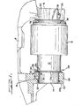
- Figure 1 is a partially cross-sectional side view of a ring seal assembly mounted on a vehicle axis.
- a vehicle bolster 8 supporting an axle 10, which can be a shaft or any other tubular member, having a differential 12.
- the axle 10 has its ends 14 and 16 journalled in two vehicle bolster split bearings 18.
- the axle ends 14 and 16 have a smaller diameter than the axle 10 so as to form a transition shoulder 17 at each axle end.
- the ends 14 and 16 are supported by the bearing halves 20 and 22 coupled with the bearing halves or caps 24 and 26, respectively, by bolts 28.
- a steel bushing 30 separates the axle 10 from the bearing 18.
- a lip seal 32 mounted on the outer edge of the axle end 14 in a bearing annular rabbet 33 insulates the bearing 18 from the entry of dirt and moisture from the bearing outer side 35a.
- a thrust washer 34 abuts the shoulder 17, which-is located close to the bearing inside surface 35b and limits the axle travel between the bearings 18 after the installation of the axle 10 into the bearings 18.
- a peripheral circumferential groove 36 running in the axle 10 is disposed near each rust washer 34.
- An elastomeric ring seal 38 shaped as a flat washer has a free-standing outer circumferential edge 40 and an inner circumferential edge 42 inserted into the groove 36.
- the outer edge 40 of the ring seal 38 is forced to contract by virtue of the rubber-like material compressing the ring toward the axle 10, thus giving the seal a concave or bottomless dish configuration.
- the ring seal 38 Prior to the upward mounting of the shaft or axle 10 into the upper bearing half 20 or 22, the ring seal 38 can be flipped over and away from the bearing 18. In this position the outer edge 40 of the seal 38 takes the position shown in broken lines in Figure 1, where it may be unsupported or rest against differential 12, or any other part extending radially outwardly.
- Both seals 38 are facing each other in this axle pre-assembly or maintenance position.
- the ring seals 38 can be flipped over toward the bearings 18 until the outer edge thereof rests against the inside surface 35b of the bearing 18. In this position the ring seal 38 covers the area of contact between the bearing 18 and the axle 10, as well as between the thrust surface of the washer 34 and bearing inside surface 35b, thereby protecting them from an undesirable environmental contamination and entry of any foreign matter into the grease-full space between the axle 10 and the bearing 18.
- novel ring seal which includes a flat washer-shaped piece of elastomeric material, provides a number of important advantages, such as a simple mounting and dismounting from the shaft, extremely low cost of manufacturing, repair and replacement, an assembly time reduction, etc.
- One of the most. important features of the invention is the ability of providing an interference-free installation of the shaft into the bearing means, which would be impossible to achieve with a conventional lip seal design.
- the seal allows the grease to be flushed out from under the seal during the greasing operation.
- the seal's ability to restore its original sealing position permits a flush-out of any contamination that may have entered into the bushings or thrust surfaces. Also, this permits to do away with precise manufacturing tolerances and allows a certain longitudinal axial travel of the axle in the bearing without compromising the integrity of the seal. No tools or other parts are needed for the seal alternate positioning, because it is biased to seal the designated area of protection by virtue of the elastomeric quality of the material itself.
Landscapes
- Engineering & Computer Science (AREA)
- General Engineering & Computer Science (AREA)
- Mechanical Engineering (AREA)
- Sealing With Elastic Sealing Lips (AREA)
- Sealing Devices (AREA)
- Sealing Of Bearings (AREA)
- Braking Arrangements (AREA)
Abstract
Description
- This invention pertains to grease seals and more particularly to an elastomeric ring seal facilitating an interference-free installation and maintenance of the parts and areas subject to sealing.
- Although the seal will find wide application, its advantage may be exemplified by describing the application of a seal to a tractor axle, which must be attached to an axle support called a bolster. The axle is restrained from moving axially by means of thrust washers at both the front and rear of the bolster. The axle pivot bushings and thrust surfaces are lubricated by means of periodic greasing. The life of these elements is greatly increased if contamination by environmental pollution such as dust and moisture can be kept out. Conventional lip seals used at the thrust surfaces cannot be employed, because they interfere with an axle installation and do not readily allow sealing of both thrust surfaces on the bolster and on the thrust washers. The seal of the invention is capable of keeping dust and moisture out and grease in. Also the seal is of a design which allows grease to flush out from under the seal during a greasing operation, thereby flusbng out any contamination that may have entered into pivot bushing or thrust surfaces.
- According to the present invention, a ring seal for protecting a designated area from ambient contamination, said ring seal comprising a sealing ring, means retaining
- a first part of said ring to mount said ring in the vicinity of said designated area, a further part of said ring being unrestrained and movable relative to said first part between a first position wherein said designated area is exposed and a second position wherein said designated area is sealed.
- The invention may be carried into practice in a number of ways but one specific embodiment will now be described in more detail, by way of example only, with reference to the accompanying drawing in which Figure 1 is a partially cross-sectional side view of a ring seal assembly mounted on a vehicle axis.
- Referring now to Figure 1, there is shown a vehicle bolster 8 supporting an
axle 10, which can be a shaft or any other tubular member, having adifferential 12. Theaxle 10 has itsends bolster split bearings 18. The axle ends 14 and 16 have a smaller diameter than theaxle 10 so as to form a transition shoulder 17 at each axle end. Theends bearing halves caps bolts 28. Asteel bushing 30 separates theaxle 10 from thebearing 18. Alip seal 32 mounted on the outer edge of theaxle end 14 in a bearingannular rabbet 33 insulates thebearing 18 from the entry of dirt and moisture from the bearingouter side 35a. A thrust washer 34 abuts the shoulder 17, which-is located close to the bearing inside surface 35b and limits the axle travel between thebearings 18 after the installation of theaxle 10 into thebearings 18. - A peripheral
circumferential groove 36 running in theaxle 10 is disposed near eachrust washer 34. Anelastomeric ring seal 38 shaped as a flat washer has a free-standing outercircumferential edge 40 and an innercircumferential edge 42 inserted into thegroove 36. Theouter edge 40 of thering seal 38 is forced to contract by virtue of the rubber-like material compressing the ring toward theaxle 10, thus giving the seal a concave or bottomless dish configuration. Prior to the upward mounting of the shaft or axle 10 into the upper bearinghalf ring seal 38 can be flipped over and away from thebearing 18. In this position theouter edge 40 of theseal 38 takes the position shown in broken lines in Figure 1, where it may be unsupported or rest againstdifferential 12, or any other part extending radially outwardly. Bothseals 38 are facing each other in this axle pre-assembly or maintenance position. After the axle installation is completed, i.e., thecaps upper bearing halves bolts 28, thering seals 38 can be flipped over toward thebearings 18 until the outer edge thereof rests against the inside surface 35b of thebearing 18. In this position thering seal 38 covers the area of contact between thebearing 18 and theaxle 10, as well as between the thrust surface of thewasher 34 and bearing inside surface 35b, thereby protecting them from an undesirable environmental contamination and entry of any foreign matter into the grease-full space between theaxle 10 and thebearing 18. - The afore-described novel ring seal, which includes a flat washer-shaped piece of elastomeric material, provides a number of important advantages, such as a simple mounting and dismounting from the shaft, extremely low cost of manufacturing, repair and replacement, an assembly time reduction, etc. One of the most. important features of the invention is the ability of providing an interference-free installation of the shaft into the bearing means, which would be impossible to achieve with a conventional lip seal design.
- The seal allows the grease to be flushed out from under the seal during the greasing operation. The seal's ability to restore its original sealing position permits a flush-out of any contamination that may have entered into the bushings or thrust surfaces. Also, this permits to do away with precise manufacturing tolerances and allows a certain longitudinal axial travel of the axle in the bearing without compromising the integrity of the seal. No tools or other parts are needed for the seal alternate positioning, because it is biased to seal the designated area of protection by virtue of the elastomeric quality of the material itself.
- While one embodiment of the invention has been illustrated as described herein, it will be apparent that various changes and modifications may be made therin.
Claims (8)
Applications Claiming Priority (2)
| Application Number | Priority Date | Filing Date | Title |
|---|---|---|---|
| US06/529,298 US4526377A (en) | 1983-09-06 | 1983-09-06 | Turn-over seal |
| US529298 | 1983-09-06 |
Publications (2)
| Publication Number | Publication Date |
|---|---|
| EP0139381A2 true EP0139381A2 (en) | 1985-05-02 |
| EP0139381A3 EP0139381A3 (en) | 1986-05-07 |
Family
ID=24109320
Family Applications (1)
| Application Number | Title | Priority Date | Filing Date |
|---|---|---|---|
| EP84305561A Withdrawn EP0139381A3 (en) | 1983-09-06 | 1984-08-16 | Ring seal |
Country Status (4)
| Country | Link |
|---|---|
| US (1) | US4526377A (en) |
| EP (1) | EP0139381A3 (en) |
| CA (1) | CA1239949A (en) |
| DE (1) | DE139381T1 (en) |
Cited By (1)
| Publication number | Priority date | Publication date | Assignee | Title |
|---|---|---|---|---|
| FR2709526A1 (en) * | 1993-09-02 | 1995-03-10 | Skf France | Sealing device for two moving parts rotating with respect to one another and application of the device to a rolling-contact bearing |
Families Citing this family (4)
| Publication number | Priority date | Publication date | Assignee | Title |
|---|---|---|---|---|
| US6186507B1 (en) | 1997-09-25 | 2001-02-13 | Michael R. Oldenburg | Retrofittable severe duty seal for a shaft |
| US20020011710A1 (en) * | 1997-09-25 | 2002-01-31 | Oldenburg Michael R. | Retrofittable severe duty seal for a shaft |
| US6692007B2 (en) | 2001-10-31 | 2004-02-17 | Transcom, Inc. | Seal for a shaft |
| US6886833B1 (en) * | 2002-11-18 | 2005-05-03 | System Seals, Inc. | Seal for use in confined space and method |
Citations (3)
| Publication number | Priority date | Publication date | Assignee | Title |
|---|---|---|---|---|
| US2418707A (en) * | 1944-05-27 | 1947-04-08 | Gen Electric | Lubricant seal |
| US4045035A (en) * | 1975-06-20 | 1977-08-30 | Compagnie Francaise Des Petroles | Inflatable lip seal for pipes |
| US4126316A (en) * | 1977-05-02 | 1978-11-21 | Garlock Inc. | Method of installing shaft seal with reformable shell |
Family Cites Families (4)
| Publication number | Priority date | Publication date | Assignee | Title |
|---|---|---|---|---|
| US2232325A (en) * | 1940-05-18 | 1941-02-18 | John M Hamilton | Well packer |
| US3627390A (en) * | 1969-10-02 | 1971-12-14 | Trw Inc | Static seal |
| DE2248274A1 (en) * | 1972-10-02 | 1974-04-18 | Allg Ind Commerz Walter Von We | DEVICE FOR GENERATING A SERIES OF ELECTRICAL PULSES, THE FREQUENCY OF WHICH FREQUENCY IS PROPORTIONAL TO THE SPEED OF A MOTOR VEHICLE WHEEL |
| US4126317A (en) * | 1976-05-24 | 1978-11-21 | Garlock Inc. | Seal for installing seal over splined shaft |
-
1983
- 1983-09-06 US US06/529,298 patent/US4526377A/en not_active Expired - Lifetime
-
1984
- 1984-08-09 CA CA000460675A patent/CA1239949A/en not_active Expired
- 1984-08-16 DE DE198484305561T patent/DE139381T1/en active Pending
- 1984-08-16 EP EP84305561A patent/EP0139381A3/en not_active Withdrawn
Patent Citations (3)
| Publication number | Priority date | Publication date | Assignee | Title |
|---|---|---|---|---|
| US2418707A (en) * | 1944-05-27 | 1947-04-08 | Gen Electric | Lubricant seal |
| US4045035A (en) * | 1975-06-20 | 1977-08-30 | Compagnie Francaise Des Petroles | Inflatable lip seal for pipes |
| US4126316A (en) * | 1977-05-02 | 1978-11-21 | Garlock Inc. | Method of installing shaft seal with reformable shell |
Cited By (1)
| Publication number | Priority date | Publication date | Assignee | Title |
|---|---|---|---|---|
| FR2709526A1 (en) * | 1993-09-02 | 1995-03-10 | Skf France | Sealing device for two moving parts rotating with respect to one another and application of the device to a rolling-contact bearing |
Also Published As
| Publication number | Publication date |
|---|---|
| CA1239949A (en) | 1988-08-02 |
| DE139381T1 (en) | 1985-12-05 |
| EP0139381A3 (en) | 1986-05-07 |
| US4526377A (en) | 1985-07-02 |
Similar Documents
| Publication | Publication Date | Title |
|---|---|---|
| US5292199A (en) | Axle wheel seal and bearing arrangement for a motor vehicle | |
| EP0304160B1 (en) | Seal assembly | |
| US6450503B1 (en) | Box-type seal assembly, in particular for vehicle axles | |
| US4252329A (en) | Semi-unitized shaft seal | |
| CA1101901A (en) | Two-element lip-type seal | |
| EP1039161B1 (en) | Shaft seal | |
| US3910128A (en) | Track roller having resilient mounted treads and threaded-on retainers | |
| US4285526A (en) | Sealing device for bearings, especially roll bearings | |
| US5794940A (en) | End face seal with sacrificial wear-in excluder | |
| US3207521A (en) | Seal assembly | |
| JP2000509791A (en) | Sealing device for bearing structure and structure for sealing bearing device | |
| US4311346A (en) | Track assembly hinge joint | |
| US3441288A (en) | Steering knuckle sealing means | |
| US4244588A (en) | Shear seal assembly | |
| US3843216A (en) | Cylindrical bearing assembly | |
| US3622165A (en) | Seal for track pins and the like | |
| EP0139381A2 (en) | Ring seal | |
| US3305281A (en) | Idler arm repair kit | |
| US5062720A (en) | Replacement bearing for worn shafts | |
| JP4073655B2 (en) | Seal unit for rotating machine parts and seal unit for casting roller | |
| US4103932A (en) | Pivot construction for a motor vehicle suspension system | |
| US2868562A (en) | Face seal means | |
| US4373739A (en) | Axle bolster pivot assembly | |
| US3166362A (en) | Intermediate propeller shaft bearings means | |
| US5286038A (en) | Unitized seal for heavy duty application |
Legal Events
| Date | Code | Title | Description |
|---|---|---|---|
| PUAI | Public reference made under article 153(3) epc to a published international application that has entered the european phase |
Free format text: ORIGINAL CODE: 0009012 |
|
| AK | Designated contracting states |
Designated state(s): DE FR GB |
|
| EL | Fr: translation of claims filed | ||
| RAP1 | Party data changed (applicant data changed or rights of an application transferred) |
Owner name: J. I. CASE COMPANY |
|
| DET | De: translation of patent claims | ||
| PUAL | Search report despatched |
Free format text: ORIGINAL CODE: 0009013 |
|
| AK | Designated contracting states |
Kind code of ref document: A3 Designated state(s): DE FR GB |
|
| 17P | Request for examination filed |
Effective date: 19861008 |
|
| 17Q | First examination report despatched |
Effective date: 19870826 |
|
| STAA | Information on the status of an ep patent application or granted ep patent |
Free format text: STATUS: THE APPLICATION IS DEEMED TO BE WITHDRAWN |
|
| 18D | Application deemed to be withdrawn |
Effective date: 19880421 |
|
| RIN1 | Information on inventor provided before grant (corrected) |
Inventor name: OLSSON, NILS O. Inventor name: HALE, RICHARD A. Inventor name: REIFF, THOMAS F. |