EP0139059A1 - Improvements in or relating to communication links and locking systems - Google Patents
Improvements in or relating to communication links and locking systems Download PDFInfo
- Publication number
- EP0139059A1 EP0139059A1 EP83306518A EP83306518A EP0139059A1 EP 0139059 A1 EP0139059 A1 EP 0139059A1 EP 83306518 A EP83306518 A EP 83306518A EP 83306518 A EP83306518 A EP 83306518A EP 0139059 A1 EP0139059 A1 EP 0139059A1
- Authority
- EP
- European Patent Office
- Prior art keywords
- receiver
- code
- transmitter
- signal
- predetermined
- Prior art date
- Legal status (The legal status is an assumption and is not a legal conclusion. Google has not performed a legal analysis and makes no representation as to the accuracy of the status listed.)
- Withdrawn
Links
Images


Classifications
-
- G—PHYSICS
- G07—CHECKING-DEVICES
- G07C—TIME OR ATTENDANCE REGISTERS; REGISTERING OR INDICATING THE WORKING OF MACHINES; GENERATING RANDOM NUMBERS; VOTING OR LOTTERY APPARATUS; ARRANGEMENTS, SYSTEMS OR APPARATUS FOR CHECKING NOT PROVIDED FOR ELSEWHERE
- G07C9/00—Individual registration on entry or exit
- G07C9/00174—Electronically operated locks; Circuits therefor; Nonmechanical keys therefor, e.g. passive or active electrical keys or other data carriers without mechanical keys
- G07C9/00182—Electronically operated locks; Circuits therefor; Nonmechanical keys therefor, e.g. passive or active electrical keys or other data carriers without mechanical keys operated with unidirectional data transmission between data carrier and locks
-
- G—PHYSICS
- G07—CHECKING-DEVICES
- G07C—TIME OR ATTENDANCE REGISTERS; REGISTERING OR INDICATING THE WORKING OF MACHINES; GENERATING RANDOM NUMBERS; VOTING OR LOTTERY APPARATUS; ARRANGEMENTS, SYSTEMS OR APPARATUS FOR CHECKING NOT PROVIDED FOR ELSEWHERE
- G07C9/00—Individual registration on entry or exit
- G07C9/20—Individual registration on entry or exit involving the use of a pass
- G07C9/28—Individual registration on entry or exit involving the use of a pass the pass enabling tracking or indicating presence
-
- G—PHYSICS
- G07—CHECKING-DEVICES
- G07C—TIME OR ATTENDANCE REGISTERS; REGISTERING OR INDICATING THE WORKING OF MACHINES; GENERATING RANDOM NUMBERS; VOTING OR LOTTERY APPARATUS; ARRANGEMENTS, SYSTEMS OR APPARATUS FOR CHECKING NOT PROVIDED FOR ELSEWHERE
- G07C9/00—Individual registration on entry or exit
- G07C9/00174—Electronically operated locks; Circuits therefor; Nonmechanical keys therefor, e.g. passive or active electrical keys or other data carriers without mechanical keys
- G07C2009/00753—Electronically operated locks; Circuits therefor; Nonmechanical keys therefor, e.g. passive or active electrical keys or other data carriers without mechanical keys operated by active electrical keys
- G07C2009/00769—Electronically operated locks; Circuits therefor; Nonmechanical keys therefor, e.g. passive or active electrical keys or other data carriers without mechanical keys operated by active electrical keys with data transmission performed by wireless means
- G07C2009/00785—Electronically operated locks; Circuits therefor; Nonmechanical keys therefor, e.g. passive or active electrical keys or other data carriers without mechanical keys operated by active electrical keys with data transmission performed by wireless means by light
-
- G—PHYSICS
- G07—CHECKING-DEVICES
- G07C—TIME OR ATTENDANCE REGISTERS; REGISTERING OR INDICATING THE WORKING OF MACHINES; GENERATING RANDOM NUMBERS; VOTING OR LOTTERY APPARATUS; ARRANGEMENTS, SYSTEMS OR APPARATUS FOR CHECKING NOT PROVIDED FOR ELSEWHERE
- G07C9/00—Individual registration on entry or exit
- G07C9/00174—Electronically operated locks; Circuits therefor; Nonmechanical keys therefor, e.g. passive or active electrical keys or other data carriers without mechanical keys
- G07C2009/00753—Electronically operated locks; Circuits therefor; Nonmechanical keys therefor, e.g. passive or active electrical keys or other data carriers without mechanical keys operated by active electrical keys
- G07C2009/00769—Electronically operated locks; Circuits therefor; Nonmechanical keys therefor, e.g. passive or active electrical keys or other data carriers without mechanical keys operated by active electrical keys with data transmission performed by wireless means
- G07C2009/00801—Electronically operated locks; Circuits therefor; Nonmechanical keys therefor, e.g. passive or active electrical keys or other data carriers without mechanical keys operated by active electrical keys with data transmission performed by wireless means by acoustic waves
Definitions
- the present invention relates to communication links and to locking systems incorporating such links.
- a system may be used to control access to a vehicle and may replace many of the mechanical parts of vehicle locks.
- Such a system may also be used to control access to enclosed spaces, such as rooms, buildings, and safes. Further, such systems may be used to control access to further systems, such as data processing systems and electrical and electronic equipment in general.
- a communication link comprising a transmitter arranged to transmit a carrier wave modulated by a two-level signal and a receiver for receiving the modulated carrier wave, characterized in that the transmitter (4) is arranged transmit, in a predetermined portion of each of a plurality of consecutive time windows, a burst of carrier wave representing the first signal level or a gap in the carrier wave representing a second signal level, and the receiver (2) is arranged to provide a interference-indicating signal upon detection of signals outside the predetermined portions of the time windows.
- Such a communication link has a very high degree of immunity against interference.
- a locking system including such a communication link, in which the transmitter is arranged to transmit a predetermined code and the receiver is arranged to receive codes and-to provide an access-permitting signal when a received code is identified as the predetermined code.
- the carrier wave may comprise electromagnetic radiation, for instance in the infra-red region of the electromagnetic spectrum, or electromagnetic induction.
- the carrier wave may comprise acoustic waves of ultrasonic frequency.
- the predetermined code may be in the form of binary code representing a predetermined number and possibly including additional bits, for instance to transfer information or control signals to apparatus with which the receiver may be associated.
- additional bits may be used to control whether the access-permitting signal actuates locking or unlocking of access means, such as a door.
- the receiver is arranged to produce an alarm signal upon receipt of a number of codes, greater than a predefined number (such as 25), not identified as the predetermined code.
- a predefined number such as 25
- the system is thus provided with a high level of security against unauthorised attempts to break the code and gain access. For instance, where a binary code having 28 bits defining the predetermined code is used, and the code has at least ten non-zero bits to provide noise immunity, the chances of finding the correct code by 25 random attempts is approximately one in ten million.
- the receiver includes transmitting means for transmitting a signal indicative of tampering upon receipt of more than the predefined number of unidentified codes.
- the transmitting means may be arranged to send a predefined code, preferably different from the predetermined code, to permit identification of the system which is being subjected to tampering.
- the transmitter may include receiving means for receiving the signal indicative of tampering, and may be arranged to respond only to the predefined code.
- a method of validating a signal comprising forming the signal in a plurality of consecutive time windows such that the signal occupies predetermined portions of the time wondows and such that the signal in at least one of the predetermined portions has a non-zero level, and monitoring parts of the time windows different from the predetermined portions for the presence of signal levels which are above a predetermined value and which are thus indicative of an invalid signal.
- the locking system shown in Figure 1 comprises a transmitter 1 and a receiver 2.
- the transmitter 1 has a keyboard 3 for controlling operation thereof and an output 4 which includes in infra-red light emitting diode.
- the receiver 2 has infra-red detectors 5 for receiving infra-red signals transmitted by the transmitter 1.
- the receiver further has a plurality of inputs 6 for supplying local input and control signals to the receiver.
- the receiver is arranged to control access to an enclosed space or to electrical or electronic equipment, and control access thereto. For this purpose, a plurality of controlled devices 7 are provided. Further, an audible alarm 8 is connected to the receiver 2.
- the transmitter 1 is arranged to mudulate the infra- red signals produced by the cutput 4 with a predetermined code, for instance in the form of a binary code.
- the receiver 2 is arranged to receive infra-red signals by means of the sensors 5 and to detect the code which such signals carry. The detected code is compared with a predetermined code in the receiver and, if the two codes coincide, an output signal is supplied by the receiver to the controlled devices 7.
- the controlled devices may, for instance, be electromechanical locks which are unlocked upon receipt by the receiver 2 of the correct predetermined code.
- the transmitter and receiver can replace the conventional key and lock arrangement provided for controlling access through doors or the like.
- the receiver 2 If the receiver 2 detects an incorrect code for greater than a predetermined of times, then it will prevent the control devices 7 from being actuated and sounds an alarm by means of the audible alarm 8.
- the alarm may only be disabled when the receiver receives the correct predetermined code from its corresponding transmitter.
- the transmitter 1 pressurably supplies a predetermined code in the form of binary digits which modulate the infra-red carrier.
- the binary code is thus transmitted in series and Figure 2 illustrates a possible type of code which may be used in the system of Figure 1.
- the code always begins with two start bits which always have the values 0 and 1 as shown. This alerts the receiver to the presence of the code and allows timing of the receiver to be synchronised.
- the following 28 bits define a code which is unique or essentially unique to the combination of the transmitter and receiver, so that each such combination has a different code.
- the use of 28 bits for this code provides a high degree of security as there a relatively large number of possible codes which could be employed.
- the final two bits serve to control the functioning of the receiver 2 and the associated controlled devices 7.
- the first of these bits may be zero when the receiver is to be controlled so as to actuate the controlled devices 7 and 1 when the receiver is to deactivate the controlled devices.
- zero would correspond to opening or unlocking a door and 1 would correspond to closing or locking the door.
- the second function bit may be zero to indicate that a battery which powers the transmitter 1 is nearing the end of its useful life. This bit may then be used to triggeran audible warning at the receiver 2 so that the battery of the transmitter can be replaced in good time.
- Figure 3 illustrates a locking system similar to that of Figure 1 but specifically intended for use in controlling access to a vehicle.
- the parts in Figure 3 which correspond to parts in Figure 1 are referred to by like reference numerals.
- the transmitter 1 is provided with a key-board 3 having only two keys which control locking and unlocking of the vehicle or car doors.
- the sensors 5 include sensors arranged to respond to infra-red signals aimed at the doors of the car, sensors arranged to receive infra-red signals aimed at the boot and bonnet of the car, and a sensor arranged to receive signals for activating the ignition mounted on the dash-board of the car.
- the audible alarm may be located in or behind the dash-board of the car but should be audible from outside the car.
- the inputs 6 to the receiver 2 comprise a first input responsive to a central locking/unlocking switch provided in the car for manual actuation of the door locks and boot and bonnet locks.
- a second input comprises a series connection of micro-switches 9 which normally provde a closed circuit but which are opened when any of the doors,m the boot, or the bonnet is open or not properly closed.
- the receiver 2 has a plurality of outputs 10 which control central locking of the doors, boot, and bonnet, the ignition system, an alarm such as a siren or the car lorn, an alarm transmitter, and the interior light of the car.
- Operation of the locking system shown in Figure 3 is as follows , starting with an unlocking operation assuming that a driver wishes to gain access to the car, all of whose doors are closed and locked.
- the owner or driver of the car has, in place of the conventional door key, transmitter 1 which contained the correct predetermined code for operating the receiver 2.
- the driver thus aims the transmitter 1 at one of the door sensors 5 and presses the one of the buttons of the keyboard 3 for opening or unlocking the door locks.
- the receiver 2 receives the predetermined code, checks this against its stored predetermined code and as a result of the coincidence therebetween unlocks the door locks.
- the incorrect transmitter is used to attempt to open the car, then the code received by the receiver 2 is not identified as the predetermined code and the door locks remain locked.
- the receiver 2 is programmed so as to allow a relatively small number of attempts, for instance 25, to be made to open the door, after which an alarm signal is provided, for instance by means of the vehicle horn, the door locks remaining locked.
- a signal is supplied to the ignition control, but rendering the engine of the vehicle inoperative .
- the control signal is set to the alarm transmitter (not shown) which sends via a radio frequency carrier a signal to the owner and possibly also to the local police station as indicated in Fig.4.
- Figure 4 illustrates the incorrect transmitter at 1' and shows an apparatus 11 located at a local police station 12.
- the alarm transmitter send a code, different from the predetermined co;e of the receiver, which is unique to the transnitter 1.
- the transmitter 1 includes a receiving means which receives this code and emits an audible alarm to warn the driver that q n attempt is being made to break into the vehicle 13.
- the signal transmitted by the alarm transmitter may also include details of the code which is being used by the incorrect transmitter 1' and this information may be used by the police to assist in identifying the person attempting to break into the car.
- the apparatus 11 may display this code and may supply it to an on-line computer terminal 14 which has access to a data base, so as to attempt to identify the person the incorrect transmitter 1'.
- the only way in which the signal transmitted by the alarm transmitter can be disabled is by using the correct transmitter 1 to supply its predetermined code to the receiver 2 in the car.
- the locking system provides a high degree of security as regards gaining -access to the car.
- the receiver 2 contains a microprocessor for controlling all operations of the locking system.
- the microprocessor is controlled by a programmefor instance stored in a programmable read-only memory.
- a single "bleep" which is audible outside the car is produced by means of the audible alarm 8.
- pressing of the "open" key of the keyboard 3 causes the locks of the car to be unlocked and the bleep indicates this to the driver.
- the device 8 produces five bleeps. This canbe caused, not only by the use of an incorrect code, but also by poor aiming of the transmitter, thus indicating that the driver should approach closer to the car, aim the transmitter more accurately and try again.
- the doors may all be locked by means of a central locking switch on the dashboard.
- a central locking switch on the dashboard.
- Such locking switches are already present in many types of cars, but other types of cars may be adapted appropriately by providing a central locking system. If all the doors, the bonnet and the boot are closed so that all the microswitches 9 are closed, two bleeps are produced by the device 8 and all the locks are locked. However, if any microswitch 9 is open, no bleep is produced and, optionally, the ignition system is disabled so that the car cannot be driven until all doors and the like are closed. The ignition system is enabled by again actuating the transmitter 1 and directing it towards the ignition sensor 5, after which the engine may be started and the car may be driven.
- the driver uses the central locking switch to unlock all the doors and the occupants leave the car and close the doors.
- the driver may then press the "close" button of the keyboard 3 while directing the transmitter 1 towards the appropriate door sensor 5.
- the device 8 produces a continuous bleep so that the offending door or the like can be closed and the appropriate button on the transmitter pressed again. Assuming that all doors and the like are not closed, two bleeps are sounded by the device 8 and all the locks are locked.
- microswitches 9 will be opened so that the receiver produces an alarm and disables the ignition.
- the microprocessor of the receiver 2 is further programmed to cause an alarm whenever disconnection and reconnection of the car battery takes place, so that the system cannot be immobilised by temporarily disconnecting the battery. Such an alarm can be immobilised only by operating the correct transmitter 1, for instance should it be necessary to remove or replace the battery.
- the microprocessor contained within the receiver 2 is programmed so that the receiver is sensitive only to codes having the correct format.
- the transmitter 1 is arranged to supply each digit of the code during a predetermined initial portion of a corresponding time window, which may for instance be 4.096 m/seconds . Between each digit, there is a period of 2.9 m/seconds in each time window when no information is transmitted.
- the microprocessor of the receiver 2 continues monitoring during this listening period and, if any none - zero signals are detected, then the input signal is assumed to be noise and is disregarded by the receiver 2.
- the system has a very high degree of immunity to noise or other spurious signals.
- the predetermined code contains a number of binary digit ones. For instance in a preferred embodiment, it is a requirement that every predetermined code should have a minimum of ten ones. In the case of a system employing a predetermined code of 28 nits, in which the system permits 25 attempts to supply tve co correct predetermined code before raising an alarm, this provides only one chance in ten million of an authorised person being able to find the correct code.
- the transmitter 1 may be provided with a larger keyboard for instance a ten digit neumeric keyboard allowing neumerical data to be sent to equipment to be controlled.
- the keyboard may comprise a miniture ASCII keyboard, for instance of the type used with pocket computers, to allow messages to be typed into devices, such as the front door of a company building provided with a receiver connected into an office communication system or a cash point terminal.
- the locking system of Figure 3 may be used to replace completely the mechanical system using a conventional key in motor cars and the like. Further, the system gives a much higher degree of security to a vehicle than is possible with conventional mechanical locking arrangements. Further the system may include any combination of the following features:
- Such a system thus has substantial advantages with respect to the conventional mechanical locking system used. for instance, in vehicles. For instance, problems caused by the conventional exposed mechanical locking mechanisms, such as freezing up, are completely avoided as the system operates electronically and need have no exposed parts. Such a system is also easier to operate by the aged and disabled as the locking function can be performed remotely. Further, when such a system is used to control access, for instance, to a safe or building, each employee may be given a transmitter having a different predetermined code and the receiver may be made sensitive to these codes. Thus. it is possible at any time to establish who is in the building. Further, the system may be used to perform a "clocking-in" function for employees.
- FIG. 5 is a circuit diagram of the receiver shown in Figure 3.
- Each of the infra-red sensors 5 comprises an infra-red sensitive diode 15 connected to a pulse amplifier comprising transisters 16, 17 and 18.
- the sensors 5 are disposed adjacent the doors, boot, and bonnet of the vehicle and are connected via respective screened leads 19 to respective diodes 20.
- the diodes 20 and the following amplifier including transistor 21 form an OR gate with the output of the amplifier being connected to an integrated circuit 22 which functions as a monostable multivibrator having a pulse period of approximately 0.47 m/seconds.
- the output signal from the monostable multivibrator are supplied via a gate 23 connected as a buffer to an input IRQ of an integrated circuit microprocessor 24 which commences decoding of the received code as soon as a start pulse of logic level is received.
- the output signals of the monostable multivibrator are also supplied to the least significant line of a data buzz via a tri-state buffer 25. All addressed decoding functions for input and output devices is provided by means of an address decoder integrated circuit 26.
- a logic level 1 is supplied to the input IRQ or the microprocessor 24 at an interrupt signal during a listening period as decribed hereinabove, the microprocessor sets a flag NOISE in its own random access memory.
- a softwear timing loop then provides a delay of half a second, after which the program resets. This operation is illustrated in the flow diagramm shown in Fig.6 of the drawings, further description of which will be given hereinafter.
- the door, bonnet and boot microswitches 9 and a central locking switch 27 are connected, via respective resistor-capacitor networks for suppressing contact balance effects, to the inputs of respective gates 28, 29 and 30.
- the outputs of these gates are connected via inverters 31 to 34, together with the output of the gate 25. to the least significant line Do of the data bus, whereas the outputs of the gates 28 and 29 and of the inverter 31 are connected via an OR gate 35 to the input of a second monostable multivibrator 36.
- the output of the monostable multivibrator 36 is connected to an input NMI of the microprocessor 24 to supply non-maskable interrupt signals thereto.
- the receiver includes first and second relays 37 and 38 having contacts for operating the "open” and “closed” relays respectively of the car.
- the windings of the relays 37 and 38 are connected to respective outputs of a latch 39 which receives enable signals via an inverter 40 from the address decoder 26.
- a third relay 41 is provided for controlling the car horn relay and has a winding connected to an output of a latch 42.
- the device 8 in Figure 3 is constituted by a piezo electric sounder connected via a buffer transistor 43 to another output of the latch 42. Enable signals for the latch 42 are supplied via an inverter 44 from an output of the address decoder 26.
- the receiver shown in Figure 5 has various other parts such as a read-only memory 45, a power supply 46, and a switch-on reset circuit 47, with the microprocessor 24 and the read-only memory 45 being connected together by address and data buses.
- Figure 6 is a flow diagram illustrating operation of the microprocessor 24 in the receiver of Figure 5.
- the circuit Upon connecting the battery to the receiver, the circuit is reset and this causes the horn to sound, thus preventing a potential thief from disabling the alarm by temporarily disconecting the battery.
- the only way in which the horn may then be stopped is by the receiver decoding its predetermined code as stored in the read-only memory 45.
- the predetermined code for the receiver, and also for the transmitter may be changeable, for instance by means of 7 hex switches so that the predetermined code may be changed from time to time.
- a routine IRQ Upon receipt of a start pulse, a routine IRQ is started and decodes the input data stream to supply the result into four bites of the random access memory of the microprocessor. The number of logic level 1's is counted by the subroutine CTBITS and, if less than ten, a reset occurs and the input is assumed to be noise.
- the received and decoded input code is compared with the stored predetermined code and. in the absence of a match, a counter BADCT is incremented. If this happens more than, for instance, 25 times, then the alarm is raised. This alarm can only be disabled by receipt of the correct code. Each time an incorrect code is received, five bleeps are produced by the piezo electric sounder.
- a subroutine OPENCL Upon receipt of the correct predetermined code, a subroutine OPENCL decodes the open/close function bit of the received code. If this function bit indicates "close” and not all of the doors, boot and bonnet are fully closed the a continuous bleep results which can be stopped only by closing the door and resending the "close” code.
- a subroutine TSTBAT then inspects the last function bit and, if this is a logic level zero, causes a pulsing bleep to be produced by the sounder until the driver operates th internal central locking switch. This provides a reminder to the driver to replace the battery in the transmitter. However, with the transmitter circuit described hereinafter, this is unlikely to occur within the life of a car because of the low coned consumption of the transmitter.
- Operation of the central locking switch causes a non-maskable interrupt NKI, according to which the microprocessor inspects the state of the central locking switch to ascertain whether an open or closed command has been made. If neither command has been made, then the microprocessor inspects the microswitches, which can also signal a non-maskable interrupt N,O.
- an open command is received, the door locks are opened.
- a close command is received and a door is still open, a continuous bleep is made by the sounder indicating danger to occupants of the car if it were to be driven. Otherwise, the doors are locked.
- FIG 7 is a circuit diagram of the transmitter 1 of Figure 3.
- the transmitter comprises an oscillator/ divider integrated circuit 48 to which is connected a 1 MHz quartz crystal 49 for controlling the frequency of operation.
- the divider of the integrated circuit 48 divides the 1 MHz output of the oscillator by numerals 4096 to provide output pulses on a line 50 having a period of 4.096 m/seconds.
- the transmitter further comprises four 8 bit parallel input serial output shift registers 51 to 54, each having a clock input connected to the line 50.
- the cascade connected shift registers thus have a combined capacity of 32 bits.
- the first 30 parallel inputs are connected to logic levels defining the start bits and the predetermined code.
- the 31st bit of this shift register arrangement is connected via a resistor 55 to the "close" key switch 56 and to one end of a parallel arrangement comprising a resistor 57 and a capacitor 58.
- the 32nd bit of the shift register arrangement is connected to the output of a Schmidt trigger gate 59 connected as an inverter.
- the input of the gate 59 is connected to a potential divider comprising a resistor 60 and a variable resistor 61, across which is connected a zener diode 62.
- the load inputs of the shift registers 51 to 54 are connected to the output of a gate 63 connected as an inverter.
- the input of the gate 63 is connected to a switch-on delay circuit comprising a resistor 64 and a capacitor 65.
- the output of the shift register 54 is connected to one input of a Schmitt trigger AND gate 66, whose other input if connected via a delay circuit comprising a resistor 67 and a capacitor 68 to the line 50 so as to receive the output pulses from the integrated circuit 48.
- the output of the gate 66 is connected via another gate 69 wired as an inverter and via a capacitor 70 to the base of a transistor 71, which has a diode 72 connected in antiparallel with the base-emitter junction to prevent transmission of a spurious "'1" when the "open" key switch is actuated.
- the collector of the transistor 71 is connected to an infra-red light emitting diode 73.
- a mercury cell battery 74 supplies power to the transmitter via the key switch 56 or the "open" key switch 75, a diode 76 being provided to isolate the capacitor 58 and the resistor 57 from the power supply line when the key switch 75 is actuated.
- Capacitors 77 and 78 perform a debouncing function for the key switches 56 and 75.
- the battery 74 is disconnected from the circuit of the transmitter to provide zero quiescent power consumption for the transmitter.
- the gate 59 and associated circuitry supply a logic level zero or one signal to the last input of the shift register 51 according to whether the battery condition is too low or adequate.
- the resistors 55 and 57 supply a logic level zero signal to the penultimate input of the shift register whereas, when the key switch 56 is actuated, a logic level 1 is supplied to this input.
- the battery Upon actuation of either key switch, the battery is connected to the power supply lines of the transmitter and the delay circuit comprising the resistor 64 and the capacitor 65 supplies, via the gate 63, a load signal for a predetermined period, such as 90 m/seconds .
- a load signal for a predetermined period, such as 90 m/seconds .
- the shift registers are then clocked by the output pulses from the integrated circuit 48 and the output pulses of the shift register 54 are combined in the NAND gate 66 with the delayed output pulses.
- the output pulses from the gate 66 control transmission by the diode 73 of infra-red pulses.
- the transmitter of Figure 7 is constructed entirely from CMOS integrated circuits so as to have a very low battery consumption, for instance of 2 m/amps , when one of the key switches 56 and 75 is actuated. Further, the output pulses corresponding to logic level 1's at the output of the gate 66 are very narrow,thus also aiding the relatively low current consumption of the circuit.
- the debouncing capacitors 77 and 78 has sufficient capacity to ensure that transmission of the complete code stored in the shift registers occurs even for only a momentry closure of either of the key switches 56 and 75.
Abstract
A locking system comprises a transmitter 1 which transmits a predetermined code by non-contact means, such as infrared waves. A receiver 2 receives the codes and provides an access-permitting signal, for instance to a vehicle door lock, when a received code is identified as the predetermined code.
Description
- The present invention relates to communication links and to locking systems incorporating such links. Such a system may be used to control access to a vehicle and may replace many of the mechanical parts of vehicle locks. Such a system may also be used to control access to enclosed spaces, such as rooms, buildings, and safes. Further, such systems may be used to control access to further systems, such as data processing systems and electrical and electronic equipment in general.
- According to the invention, there is provided a communication link comprising a transmitter arranged to transmit a carrier wave modulated by a two-level signal and a receiver for receiving the modulated carrier wave, characterized in that the transmitter (4) is arranged transmit, in a predetermined portion of each of a plurality of consecutive time windows, a burst of carrier wave representing the first signal level or a gap in the carrier wave representing a second signal level, and the receiver (2) is arranged to provide a interference-indicating signal upon detection of signals outside the predetermined portions of the time windows. Such a communication link has a very high degree of immunity against interference.
- According to the invention, there is also provided a locking system including such a communication link, in which the transmitter is arranged to transmit a predetermined code and the receiver is arranged to receive codes and-to provide an access-permitting signal when a received code is identified as the predetermined code.
- The carrier wave may comprise electromagnetic radiation, for instance in the infra-red region of the electromagnetic spectrum, or electromagnetic induction. Alternatively, the carrier wave may comprise acoustic waves of ultrasonic frequency.
- The predetermined code may be in the form of binary code representing a predetermined number and possibly including additional bits, for instance to transfer information or control signals to apparatus with which the receiver may be associated. When the locking system is used to control access to an enclosed space, such additional bits may be used to control whether the access-permitting signal actuates locking or unlocking of access means, such as a door.
- Preferably, the receiver is arranged to produce an alarm signal upon receipt of a number of codes, greater than a predefined number (such as 25), not identified as the predetermined code. The system is thus provided with a high level of security against unauthorised attempts to break the code and gain access. For instance, where a binary code having 28 bits defining the predetermined code is used, and the code has at least ten non-zero bits to provide noise immunity, the chances of finding the correct code by 25 random attempts is approximately one in ten million.
- Preferably, the receiver includes transmitting means for transmitting a signal indicative of tampering upon receipt of more than the predefined number of unidentified codes. The transmitting means may be arranged to send a predefined code, preferably different from the predetermined code, to permit identification of the system which is being subjected to tampering. The transmitter may include receiving means for receiving the signal indicative of tampering, and may be arranged to respond only to the predefined code.
- According to another aspect of the invention, there is provided a method of validating a signal, comprising forming the signal in a plurality of consecutive time windows such that the signal occupies predetermined portions of the time wondows and such that the signal in at least one of the predetermined portions has a non-zero level, and monitoring parts of the time windows different from the predetermined portions for the presence of signal levels which are above a predetermined value and which are thus indicative of an invalid signal.
- The invention will be further described by way of example, with reference to the accompanying drawings, in which:
- Figure 1 is a block diagram of a locking system constituting a first embodiment of the invention;
- Figure 2 illustrates the format of a predetermined code used in the system of Figure 1;
- Figure 3 is a block diagram of a locking system, for use in a motor vehicle, constituting a second embodiment of the invention;
- Figure 4 illustrates a mode of operation of the system of Figure 3;
- Figure 5 is a circuit diagram of a receiver of the system of Figure 3;
- Figure 6 is a flow diagram illustrating operation of the receiver of Figure 5; and
- Figure 7 is a circuit diagram of a transmitter of the system of Figure 3.
- The locking system shown in Figure 1 comprises a
transmitter 1 and a receiver 2. Thetransmitter 1 has akeyboard 3 for controlling operation thereof and an output 4 which includes in infra-red light emitting diode. - The receiver 2 has infra-
red detectors 5 for receiving infra-red signals transmitted by thetransmitter 1. The receiver further has a plurality ofinputs 6 for supplying local input and control signals to the receiver. The receiver is arranged to control access to an enclosed space or to electrical or electronic equipment, and control access thereto. For this purpose, a plurality of controlleddevices 7 are provided. Further, anaudible alarm 8 is connected to the receiver 2. - The
transmitter 1 is arranged to mudulate the infra- red signals produced by the cutput 4 with a predetermined code, for instance in the form of a binary code. The receiver 2 is arranged to receive infra-red signals by means of thesensors 5 and to detect the code which such signals carry. The detected code is compared with a predetermined code in the receiver and, if the two codes coincide, an output signal is supplied by the receiver to the controlleddevices 7. The controlled devices may, for instance, be electromechanical locks which are unlocked upon receipt by the receiver 2 of the correct predetermined code. Thus, the transmitter and receiver can replace the conventional key and lock arrangement provided for controlling access through doors or the like. - If the receiver 2 detects an incorrect code for greater than a predetermined of times, then it will prevent the
control devices 7 from being actuated and sounds an alarm by means of theaudible alarm 8. In a preferred embodiment, the alarm may only be disabled when the receiver receives the correct predetermined code from its corresponding transmitter. - As mentioned above, the
transmitter 1 pressurably supplies a predetermined code in the form of binary digits which modulate the infra-red carrier. The binary code is thus transmitted in series and Figure 2 illustrates a possible type of code which may be used in the system of Figure 1. The code always begins with two start bits which always have thevalues devices 7. For instance, the first of these bits may be zero when the receiver is to be controlled so as to actuate the controlleddevices transmitter 1 is nearing the end of its useful life. This bit may then be used to triggeran audible warning at the receiver 2 so that the battery of the transmitter can be replaced in good time. - Figure 3 illustrates a locking system similar to that of Figure 1 but specifically intended for use in controlling access to a vehicle. The parts in Figure 3 which correspond to parts in Figure 1 are referred to by like reference numerals. The
transmitter 1 is provided with a key-board 3 having only two keys which control locking and unlocking of the vehicle or car doors. Thesensors 5 include sensors arranged to respond to infra-red signals aimed at the doors of the car, sensors arranged to receive infra-red signals aimed at the boot and bonnet of the car, and a sensor arranged to receive signals for activating the ignition mounted on the dash-board of the car. The audible alarm may be located in or behind the dash-board of the car but should be audible from outside the car. - The
inputs 6 to the receiver 2 comprise a first input responsive to a central locking/unlocking switch provided in the car for manual actuation of the door locks and boot and bonnet locks. A second input comprises a series connection of micro-switches 9 which normally provde a closed circuit but which are opened when any of the doors,m the boot, or the bonnet is open or not properly closed. - The receiver 2 has a plurality of
outputs 10 which control central locking of the doors, boot, and bonnet, the ignition system, an alarm such as a siren or the car lorn, an alarm transmitter, and the interior light of the car. - Operation of the locking system shown in Figure 3 is as follows , starting with an unlocking operation assuming that a driver wishes to gain access to the car, all of whose doors are closed and locked. The owner or driver of the car has, in place of the conventional door key,
transmitter 1 which contained the correct predetermined code for operating the receiver 2. The driver thus aims thetransmitter 1 at one of thedoor sensors 5 and presses the one of the buttons of thekeyboard 3 for opening or unlocking the door locks. The receiver 2 receives the predetermined code, checks this against its stored predetermined code and as a result of the coincidence therebetween unlocks the door locks. - However, if the incorrect transmitter is used to attempt to open the car, then the code received by the receiver 2 is not identified as the predetermined code and the door locks remain locked. The receiver 2 is programmed so as to allow a relatively small number of attempts, for
instance 25, to be made to open the door, after which an alarm signal is provided, for instance by means of the vehicle horn, the door locks remaining locked. A signal is supplied to the ignition control, but rendering the engine of the vehicle inoperative . Further, the control signal is set to the alarm transmitter (not shown) which sends via a radio frequency carrier a signal to the owner and possibly also to the local police station as indicated in Fig.4. Figure 4 illustrates the incorrect transmitter at 1' and shows anapparatus 11 located at alocal police station 12. The alarm transmitter send a code, different from the predetermined co;e of the receiver, which is unique to thetransnitter 1. Thetransmitter 1 includes a receiving means which receives this code and emits an audible alarm to warn the driver that qn attempt is being made to break into thevehicle 13. The signal transmitted by the alarm transmitter may also include details of the code which is being used by the incorrect transmitter 1' and this information may be used by the police to assist in identifying the person attempting to break into the car. For instance, theapparatus 11 may display this code and may supply it to an on-line computer terminal 14 which has access to a data base, so as to attempt to identify the person the incorrect transmitter 1'. - The only way in which the signal transmitted by the alarm transmitter can be disabled is by using the
correct transmitter 1 to supply its predetermined code to the receiver 2 in the car. Thus, the locking system provides a high degree of security as regards gaining -access to the car. - The receiver 2 contains a microprocessor for controlling all operations of the locking system. The microprocessor is controlled by a programmefor instance stored in a programmable read-only memory. When the correct predetermined code is received by the receiver 2, a single "bleep" which is audible outside the car is produced by means of the
audible alarm 8. Thus, pressing of the "open" key of thekeyboard 3 causes the locks of the car to be unlocked and the bleep indicates this to the driver. - Each time an incorrect code is received, the
device 8 produces five bleeps. This canbe caused, not only by the use of an incorrect code, but also by poor aiming of the transmitter, thus indicating that the driver should approach closer to the car, aim the transmitter more accurately and try again. - Once the owner is inside the car, together with any passengers, the doors may all be locked by means of a central locking switch on the dashboard. Such locking switches are already present in many types of cars, but other types of cars may be adapted appropriately by providing a central locking system. If all the doors, the bonnet and the boot are closed so that all the microswitches 9 are closed, two bleeps are produced by the
device 8 and all the locks are locked. However, if any microswitch 9 is open, no bleep is produced and, optionally, the ignition system is disabled so that the car cannot be driven until all doors and the like are closed. The ignition system is enabled by again actuating thetransmitter 1 and directing it towards theignition sensor 5, after which the engine may be started and the car may be driven. - When the driver and where appropriate, passengers wish to leave the car, the driver uses the central locking switch to unlock all the doors and the occupants leave the car and close the doors. The driver may then press the "close" button of the
keyboard 3 while directing thetransmitter 1 towards theappropriate door sensor 5. Again, if any of the doors or the boot or the bonnet, is not completely closed, thedevice 8 produces a continuous bleep so that the offending door or the like can be closed and the appropriate button on the transmitter pressed again. Assuming that all doors and the like are not closed, two bleeps are sounded by thedevice 8 and all the locks are locked. If an attempt is made by an unauthorized person to gain entry to the vehicle without using any form oftransmitter 1, then one of the microswitches 9 will be opened so that the receiver produces an alarm and disables the ignition. The microprocessor of the receiver 2 is further programmed to cause an alarm whenever disconnection and reconnection of the car battery takes place, so that the system cannot be immobilised by temporarily disconnecting the battery. Such an alarm can be immobilised only by operating thecorrect transmitter 1, for instance should it be necessary to remove or replace the battery. - In order to prevent the receiver 2 responding to noise or spurious infra-red signals for instance caused by the headlight beams of passing cars, the microprocessor contained within the receiver 2 is programmed so that the receiver is sensitive only to codes having the correct format. For this purpose, the
transmitter 1 is arranged to supply each digit of the code during a predetermined initial portion of a corresponding time window, which may for instance be 4.096 m/seconds . Between each digit, there is a period of 2.9 m/seconds in each time window when no information is transmitted. The microprocessor of the receiver 2 continues monitoring during this listening period and, if any none - zero signals are detected, then the input signal is assumed to be noise and is disregarded by the receiver 2. Thus, the system has a very high degree of immunity to noise or other spurious signals. - In order to make this noise suppression system viable, it is necessary to ensure that the predetermined code contains a number of binary digit ones. For instance in a preferred embodiment, it is a requirement that every predetermined code should have a minimum of ten ones. In the case of a system employing a predetermined code of 28 nits, in which the system permits 25 attempts to supply tve co correct predetermined code before raising an alarm, this provides only one chance in ten million of an authorised person being able to find the correct code.
- Although the system shown in Figure 3 is specifically intended for use with a vehicle a similar type of system may be used to control access to data processing equipment. For instance, the
transmitter 1 may be provided with a larger keyboard for instance a ten digit neumeric keyboard allowing neumerical data to be sent to equipment to be controlled. Alternatively. the keyboard may comprise a miniture ASCII keyboard, for instance of the type used with pocket computers, to allow messages to be typed into devices, such as the front door of a company building provided with a receiver connected into an office communication system or a cash point terminal. - The locking system of Figure 3 may be used to replace completely the mechanical system using a conventional key in motor cars and the like. Further, the system gives a much higher degree of security to a vehicle than is possible with conventional mechanical locking arrangements. Further the system may include any combination of the following features:
- Use of a
transmitter 1 without an ON-OFF switch with the buttons of thekeyboard 3 serving to activate the transmitter by connection of the battery, thus giving a life span to the battery of, for instance, ten years; - the presence of a Schmitt Trigger in the
transmitter 1 for detecting when the battery condition is low and to supply a signal to the receiver to warn the user; - arrangement of the microswitches 9 to activate a non-maskable interrupt of the micro-processor in the
receiver 3 to indicate an attempted forced entry; - Correct operation of the system indirect sunlight by using as each of the
sensors 5 an infra-red receiving diode which is heavily reversed biased. - Such a system thus has substantial advantages with respect to the conventional mechanical locking system used. for instance, in vehicles. For instance, problems caused by the conventional exposed mechanical locking mechanisms, such as freezing up, are completely avoided as the system operates electronically and need have no exposed parts. Such a system is also easier to operate by the aged and disabled as the locking function can be performed remotely. Further, when such a system is used to control access, for instance, to a safe or building, each employee may be given a transmitter having a different predetermined code and the receiver may be made sensitive to these codes. Thus. it is possible at any time to establish who is in the building. Further, the system may be used to perform a "clocking-in" function for employees.
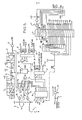
- Figure 5 is a circuit diagram of the receiver shown in Figure 3. Each of the infra-
red sensors 5 comprises an infra-redsensitive diode 15 connected to a pulseamplifier comprising transisters sensors 5 are disposed adjacent the doors, boot, and bonnet of the vehicle and are connected via respective screened leads 19 to respective diodes 20. The diodes 20 and the followingamplifier including transistor 21 form an OR gate with the output of the amplifier being connected to anintegrated circuit 22 which functions as a monostable multivibrator having a pulse period of approximately 0.47 m/seconds. The output signal from the monostable multivibrator are supplied via agate 23 connected as a buffer to an inputIRQ of anintegrated circuit microprocessor 24 which commences decoding of the received code as soon as a start pulse of logic level is received. The output signals of the monostable multivibrator are also supplied to the least significant line of a data buzz via atri-state buffer 25. All addressed decoding functions for input and output devices is provided by means of an address decoder integratedcircuit 26. - Whenever a
logic level 1 is supplied to the inputIRQ or themicroprocessor 24 at an interrupt signal during a listening period as decribed hereinabove, the microprocessor sets a flag NOISE in its own random access memory. A softwear timing loop then provides a delay of half a second, after which the program resets. This operation is illustrated in the flow diagramm shown in Fig.6 of the drawings, further description of which will be given hereinafter. - The door, bonnet and boot microswitches 9 and a
central locking switch 27 are connected, via respective resistor-capacitor networks for suppressing contact balance effects, to the inputs ofrespective gates gate 25. to the least significant line Do of the data bus, whereas the outputs of thegates OR gate 35 to the input of a secondmonostable multivibrator 36. The output of themonostable multivibrator 36 is connected to an input NMI of themicroprocessor 24 to supply non-maskable interrupt signals thereto. - It is assumed that the vehicle incorporating the receiver shown in Figure 5 already has a central locking system including "open" and "closed" relays for operating the solenoid locks of the car doors, the boot and the bonnet. The receiver includes first and
second relays relays latch 39 which receives enable signals via aninverter 40 from theaddress decoder 26. Athird relay 41 is provided for controlling the car horn relay and has a winding connected to an output of alatch 42. Thedevice 8 in Figure 3 is constituted by a piezo electric sounder connected via a buffer transistor 43 to another output of thelatch 42. Enable signals for thelatch 42 are supplied via an inverter 44 from an output of theaddress decoder 26. - The receiver shown in Figure 5 has various other parts such as a read-
only memory 45, apower supply 46, and a switch-on reset circuit 47, with themicroprocessor 24 and the read-only memory 45 being connected together by address and data buses. - Figure 6 is a flow diagram illustrating operation of the
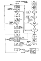
microprocessor 24 in the receiver of Figure 5. Upon connecting the battery to the receiver, the circuit is reset and this causes the horn to sound, thus preventing a potential thief from disabling the alarm by temporarily disconecting the battery. The only way in which the horn may then be stopped is by the receiver decoding its predetermined code as stored in the read-only memory 45.. Alternatively, the predetermined code for the receiver, and also for the transmitter, may be changeable, for instance by means of 7 hex switches so that the predetermined code may be changed from time to time. - Upon receipt of a start pulse, a routine
IRQ is started and decodes the input data stream to supply the result into four bites of the random access memory of the microprocessor. The number oflogic level 1's is counted by the subroutine CTBITS and, if less than ten, a reset occurs and the input is assumed to be noise. - The received and decoded input code is compared with the stored predetermined code and. in the absence of a match, a counter BADCT is incremented. If this happens more than, for instance, 25 times, then the alarm is raised. This alarm can only be disabled by receipt of the correct code. Each time an incorrect code is received, five bleeps are produced by the piezo electric sounder.
- Upon receipt of the correct predetermined code, a subroutine OPENCL decodes the open/close function bit of the received code. If this function bit indicates "close" and not all of the doors, boot and bonnet are fully closed the a continuous bleep results which can be stopped only by closing the door and resending the "close" code.
- A subroutine TSTBAT then inspects the last function bit and, if this is a logic level zero, causes a pulsing bleep to be produced by the sounder until the driver operates th internal central locking switch. This provides a reminder to the driver to replace the battery in the transmitter. However, with the transmitter circuit described hereinafter, this is unlikely to occur within the life of a car because of the low coned consumption of the transmitter.
- Operation of the central locking switch causes a non-maskable interrupt NKI, according to which the microprocessor inspects the state of the central locking switch to ascertain whether an open or closed command has been made. If neither command has been made, then the microprocessor inspects the microswitches, which can also signal a non-maskable interrupt N,O. When an open command is received, the door locks are opened. When a close command is received and a door is still open, a continuous bleep is made by the sounder indicating danger to occupants of the car if it were to be driven. Otherwise, the doors are locked. If the interrupt signal comes from a door microswitch and BSTATE = 1 (i.e. the last command was to lock the door) then this represents a forced door opening and an alarm is sounded. The only way in which the alarm can then be stopped is by receipt of the correct predetermined code.
- Figure 7 is a circuit diagram of the
transmitter 1 of Figure 3. The transmitter comprises an oscillator/ divider integratedcircuit 48 to which is connected a 1MHz quartz crystal 49 for controlling the frequency of operation. The divider of theintegrated circuit 48 divides the 1 MHz output of the oscillator by numerals 4096 to provide output pulses on aline 50 having a period of 4.096 m/seconds. - The transmitter further comprises four 8 bit parallel input serial
output shift registers 51 to 54, each having a clock input connected to theline 50. The cascade connected shift registers thus have a combined capacity of 32 bits. Starting from the right hand end of the cascade connected shift registers, the first 30 parallel inputs are connected to logic levels defining the start bits and the predetermined code. The 31st bit of this shift register arrangement is connected via aresistor 55 to the "close"key switch 56 and to one end of a parallel arrangement comprising aresistor 57 and acapacitor 58. The 32nd bit of the shift register arrangement is connected to the output of aSchmidt trigger gate 59 connected as an inverter. The input of thegate 59 is connected to a potential divider comprising aresistor 60 and avariable resistor 61, across which is connected azener diode 62. - The load inputs of the shift registers 51 to 54 are connected to the output of a
gate 63 connected as an inverter. The input of thegate 63 is connected to a switch-on delay circuit comprising aresistor 64 and acapacitor 65. - The output of the
shift register 54 is connected to one input of a Schmitt trigger ANDgate 66, whose other input if connected via a delay circuit comprising aresistor 67 and acapacitor 68 to theline 50 so as to receive the output pulses from the integratedcircuit 48. The output of thegate 66 is connected via anothergate 69 wired as an inverter and via a capacitor 70 to the base of atransistor 71, which has adiode 72 connected in antiparallel with the base-emitter junction to prevent transmission of a spurious "'1" when the "open" key switch is actuated. The collector of thetransistor 71 is connected to an infra-redlight emitting diode 73. - A
mercury cell battery 74 supplies power to the transmitter via thekey switch 56 or the "open"key switch 75, a diode 76 being provided to isolate thecapacitor 58 and theresistor 57 from the power supply line when thekey switch 75 is actuated.Capacitors 77 and 78 perform a debouncing function for thekey switches - Until one of the
key switches battery 74 is disconnected from the circuit of the transmitter to provide zero quiescent power consumption for the transmitter. Thegate 59 and associated circuitry supply a logic level zero or one signal to the last input of theshift register 51 according to whether the battery condition is too low or adequate. When thekey switch 75 is closed, theresistors key switch 56 is actuated, alogic level 1 is supplied to this input. Upon actuation of either key switch, the battery is connected to the power supply lines of the transmitter and the delay circuit comprising theresistor 64 and thecapacitor 65 supplies, via thegate 63, a load signal for a predetermined period, such as 90 m/seconds . Thus, the logic levels present at the parallel inputs of the shift registers 51 to 54 are loaded in the registers. The shift registers are then clocked by the output pulses from the integratedcircuit 48 and the output pulses of theshift register 54 are combined in theNAND gate 66 with the delayed output pulses. The output pulses from thegate 66 control transmission by thediode 73 of infra-red pulses. - The transmitter of Figure 7 is constructed entirely from CMOS integrated circuits so as to have a very low battery consumption, for instance of 2 m/amps , when one of the
key switches logic level 1's at the output of thegate 66 are very narrow,thus also aiding the relatively low current consumption of the circuit. The The debouncingcapacitors 77 and 78 has sufficient capacity to ensure that transmission of the complete code stored in the shift registers occurs even for only a momentry closure of either of thekey switches
Claims (9)
1. A communication link comprising a transmitter arranged to transmit a carrier wave modulated by a two-level signal and a receiver for receiving the modulated carrier wave, characterized in that the transmitter (4) is arranged transmit, in a predetermined portion of each of a plurality of consecutive time windows, a burst of carrier wave representing the first signal level or a gap in the carrier wave representing a second signal level, and the receiver (2) is arranged to provide a interference-indicating signal upon detection of signals outside the predetermined portions of the time windows.
2. A locking system including a communication link as claimed in claim 1, in which the transmitter (4) is arranged to transmit a predetermined code and the receiver (2) is arranged to receive codes and to provide an access-permitting signal when a received code is identified as the predetermined code.
3. A system as claimed in claim 2, in which the carrier wave comprises infra-red electromagnetic radiation.
4. A system as claimed in claim 2, in which the carrier wave comprises ultrasonic acoustic waves.
5. A system as claimed in any one of claims 2 to 4, in which the predetermined code is in the form of binary code representing a predetermined number.
6. A system as claimed in any one of claims 2 to 5, in which the receiver (2) is arranged to produce an alarm signal upon receipt of a number of codes, greater than a predefined number, not identified as the predetermined code.
7. A system as claimed in claim 6, in which the receiver (2) includes transmitting means for transmitting a signal indicative of tampering upon receipt of more than the predefined number of unidentified codes.
8. A system as claimed in claim 7, in which the transmitting means is arranged to send a predefined code, different from the predetermined code, to permit identification of the system which is being subjected to tampering.
9. A system as claimed in claim 8, in which the transmitter (2) includes receiving means for receiving the signal indicative of tampering, and is arranged to respond only to the predefined code.
Priority Applications (1)
| Application Number | Priority Date | Filing Date | Title |
|---|---|---|---|
| EP83306518A EP0139059A1 (en) | 1983-10-26 | 1983-10-26 | Improvements in or relating to communication links and locking systems |
Applications Claiming Priority (1)
| Application Number | Priority Date | Filing Date | Title |
|---|---|---|---|
| EP83306518A EP0139059A1 (en) | 1983-10-26 | 1983-10-26 | Improvements in or relating to communication links and locking systems |
Publications (1)
| Publication Number | Publication Date |
|---|---|
| EP0139059A1 true EP0139059A1 (en) | 1985-05-02 |
Family
ID=8191328
Family Applications (1)
| Application Number | Title | Priority Date | Filing Date |
|---|---|---|---|
| EP83306518A Withdrawn EP0139059A1 (en) | 1983-10-26 | 1983-10-26 | Improvements in or relating to communication links and locking systems |
Country Status (1)
| Country | Link |
|---|---|
| EP (1) | EP0139059A1 (en) |
Cited By (10)
| Publication number | Priority date | Publication date | Assignee | Title |
|---|---|---|---|---|
| EP0203262A2 (en) * | 1985-05-28 | 1986-12-03 | David Arlasky | Anti-theft system for a vehicle |
| FR2582708A1 (en) * | 1985-06-04 | 1986-12-05 | Gerard Michel | Secret code remote control device for a lock |
| EP0306598A2 (en) * | 1987-09-08 | 1989-03-15 | Clifford Electronics, Inc. | Electronically programmable remote control access systems |
| WO1992002702A1 (en) * | 1990-08-08 | 1992-02-20 | Trw Inc. | Remote programming of vehicle functions |
| GB2252783A (en) * | 1991-02-06 | 1992-08-19 | Rover Group | A vehicle door locking system |
| EP0582523A1 (en) * | 1992-08-06 | 1994-02-09 | Albert Sellem | Electronic antitheft system for a motor vehicle |
| AT155U1 (en) * | 1991-01-22 | 1995-03-27 | Skidata Gmbh | DEVICE FOR AUTHORIZING THE OPERATION OF A DEVICE WITH AN ACTUATING UNIT |
| WO1996020326A1 (en) * | 1994-12-28 | 1996-07-04 | Roulleaux Robin Veronique | Self-protected closing device for preventing the theft of objects in enclosed spaces |
| US5615625A (en) * | 1993-04-05 | 1997-04-01 | First National Bank Of Southern Africa Limited | System for the secure transportation of articles |
| GB2344669A (en) * | 1998-12-11 | 2000-06-14 | Shaun Kirk | Systems for controlling apparatus |
Citations (5)
| Publication number | Priority date | Publication date | Assignee | Title |
|---|---|---|---|---|
| GB2016576A (en) * | 1978-03-17 | 1979-09-26 | Neiman Sa | Control device for vehicle locks |
| DE3005890A1 (en) * | 1979-02-21 | 1980-09-11 | Amcor Ltd | ELECTRONICALLY CODED LOCKING DEVICE |
| DE2911828A1 (en) * | 1979-03-26 | 1980-10-16 | Vdo Schindling | Radio controlled door lock for vehicle - has key transmitting PCM signals to receiver in lock containing demodulator and code comparator |
| GB2051442A (en) * | 1979-03-30 | 1981-01-14 | Howard J A | A security system |
| GB2119548A (en) * | 1982-03-17 | 1983-11-16 | John Robert Carter | Locking system |
-
1983
- 1983-10-26 EP EP83306518A patent/EP0139059A1/en not_active Withdrawn
Patent Citations (5)
| Publication number | Priority date | Publication date | Assignee | Title |
|---|---|---|---|---|
| GB2016576A (en) * | 1978-03-17 | 1979-09-26 | Neiman Sa | Control device for vehicle locks |
| DE3005890A1 (en) * | 1979-02-21 | 1980-09-11 | Amcor Ltd | ELECTRONICALLY CODED LOCKING DEVICE |
| DE2911828A1 (en) * | 1979-03-26 | 1980-10-16 | Vdo Schindling | Radio controlled door lock for vehicle - has key transmitting PCM signals to receiver in lock containing demodulator and code comparator |
| GB2051442A (en) * | 1979-03-30 | 1981-01-14 | Howard J A | A security system |
| GB2119548A (en) * | 1982-03-17 | 1983-11-16 | John Robert Carter | Locking system |
Non-Patent Citations (1)
| Title |
|---|
| FUNKSCHAU, vol. 50, no. 8, April 1978, pages 323-326, Franzis-Verlag, Munich, DE; R. KARNATZKI: "Infrarot-Fernbedienung mit 1024 Befehlen" * |
Cited By (16)
| Publication number | Priority date | Publication date | Assignee | Title |
|---|---|---|---|---|
| EP0203262A3 (en) * | 1985-05-28 | 1987-09-30 | David Arlasky | Anti-theft system for a vehicle |
| EP0203262A2 (en) * | 1985-05-28 | 1986-12-03 | David Arlasky | Anti-theft system for a vehicle |
| FR2582708A1 (en) * | 1985-06-04 | 1986-12-05 | Gerard Michel | Secret code remote control device for a lock |
| EP0306598A2 (en) * | 1987-09-08 | 1989-03-15 | Clifford Electronics, Inc. | Electronically programmable remote control access systems |
| EP0306598A3 (en) * | 1987-09-08 | 1989-08-23 | Clifford Electronics, Inc. | Electronically programmable remote control access systems |
| US5650774A (en) * | 1987-09-08 | 1997-07-22 | Clifford Electronics, Inc. | Electronically programmable remote control access system |
| WO1992002702A1 (en) * | 1990-08-08 | 1992-02-20 | Trw Inc. | Remote programming of vehicle functions |
| AT155U1 (en) * | 1991-01-22 | 1995-03-27 | Skidata Gmbh | DEVICE FOR AUTHORIZING THE OPERATION OF A DEVICE WITH AN ACTUATING UNIT |
| GB2252783A (en) * | 1991-02-06 | 1992-08-19 | Rover Group | A vehicle door locking system |
| GB2252783B (en) * | 1991-02-06 | 1994-07-06 | Rover Group | A vehicle door locking system |
| FR2694592A1 (en) * | 1992-08-06 | 1994-02-11 | Sellem Albert | Electronic anti-theft system for a motor vehicle. |
| US5514914A (en) * | 1992-08-06 | 1996-05-07 | Sellem; Albert | Electronic antitheft device for a motor vehicle |
| EP0582523A1 (en) * | 1992-08-06 | 1994-02-09 | Albert Sellem | Electronic antitheft system for a motor vehicle |
| US5615625A (en) * | 1993-04-05 | 1997-04-01 | First National Bank Of Southern Africa Limited | System for the secure transportation of articles |
| WO1996020326A1 (en) * | 1994-12-28 | 1996-07-04 | Roulleaux Robin Veronique | Self-protected closing device for preventing the theft of objects in enclosed spaces |
| GB2344669A (en) * | 1998-12-11 | 2000-06-14 | Shaun Kirk | Systems for controlling apparatus |
Similar Documents
| Publication | Publication Date | Title |
|---|---|---|
| GB2119548A (en) | Locking system | |
| US6188326B1 (en) | Vehicle control system including token verification and code reset features | |
| US4327353A (en) | Security system | |
| US5986571A (en) | Building security system having remote transmitter code verification and code reset features | |
| US7190253B2 (en) | Door control system and method for vehicles | |
| US5659291A (en) | Key-in-ignition lock reminder system | |
| US6480117B1 (en) | Vehicle control system including token verification and code reset features for electrically connected token | |
| EP0139059A1 (en) | Improvements in or relating to communication links and locking systems | |
| US4996514A (en) | Car theft proofing system | |
| JPH07189538A (en) | Keyless entry device | |
| GB2246159A (en) | Car alarm | |
| EP0395596A2 (en) | An improved anti-theft system, particularly for motor vehicles | |
| US7667595B2 (en) | Security system using sequence signal | |
| US4337454A (en) | Alarm unit for preventing theft of vehicles | |
| US6104309A (en) | Anti-theft system for automotive electronic accessory with coded interlock | |
| JPH08150902A (en) | Engine starter | |
| WO1982002861A1 (en) | Security device,motor vehicle incorporating the device and method of indicating an unauthorised attempt to enter an enclosure | |
| JPS62129479A (en) | Car door lock control apparatus | |
| JP3938039B2 (en) | Vehicle anti-theft system | |
| KR900006095B1 (en) | Anti-theft device | |
| JPH06144158A (en) | Theft preventing device for vehicle | |
| JP2871412B2 (en) | Vehicle anti-theft device | |
| KR100279116B1 (en) | Burglar Vehicle Inspection System | |
| RU2123441C1 (en) | Automobile unauthorized access protection system | |
| JPH04283152A (en) | Burglar preventing device for vehicle |
Legal Events
| Date | Code | Title | Description |
|---|---|---|---|
| PUAI | Public reference made under article 153(3) epc to a published international application that has entered the european phase |
Free format text: ORIGINAL CODE: 0009012 |
|
| AK | Designated contracting states |
Designated state(s): AT BE CH DE FR IT LI LU NL SE |
|
| STAA | Information on the status of an ep patent application or granted ep patent |
Free format text: STATUS: THE APPLICATION IS DEEMED TO BE WITHDRAWN |
|
| 18D | Application deemed to be withdrawn |
Effective date: 19860106 |