EP0138576A2 - Magnetic type cartridge carrier - Google Patents
Magnetic type cartridge carrier Download PDFInfo
- Publication number
- EP0138576A2 EP0138576A2 EP84306931A EP84306931A EP0138576A2 EP 0138576 A2 EP0138576 A2 EP 0138576A2 EP 84306931 A EP84306931 A EP 84306931A EP 84306931 A EP84306931 A EP 84306931A EP 0138576 A2 EP0138576 A2 EP 0138576A2
- Authority
- EP
- European Patent Office
- Prior art keywords
- carrier
- magnetic tape
- members
- frame
- apertures
- Prior art date
- Legal status (The legal status is an assumption and is not a legal conclusion. Google has not performed a legal analysis and makes no representation as to the accuracy of the status listed.)
- Granted
Links
- 239000000969 carrier Substances 0.000 abstract description 9
- 230000000717 retained effect Effects 0.000 abstract description 6
- 241000282461 Canis lupus Species 0.000 description 1
- 239000011248 coating agent Substances 0.000 description 1
- 238000000576 coating method Methods 0.000 description 1
- 230000005484 gravity Effects 0.000 description 1
- 239000000463 material Substances 0.000 description 1
Images


Classifications
-
- G—PHYSICS
- G11—INFORMATION STORAGE
- G11B—INFORMATION STORAGE BASED ON RELATIVE MOVEMENT BETWEEN RECORD CARRIER AND TRANSDUCER
- G11B23/00—Record carriers not specific to the method of recording or reproducing; Accessories, e.g. containers, specially adapted for co-operation with the recording or reproducing apparatus ; Intermediate mediums; Apparatus or processes specially adapted for their manufacture
- G11B23/02—Containers; Storing means both adapted to cooperate with the recording or reproducing means
- G11B23/023—Containers for magazines or cassettes
Definitions
- This invention relates to a carrier for containing a plurality of tape cartridges which may be placed in a storage rack, transportation cart or carry pack and secured by a support and locking apparatus.
- U.S. Patent 4,293,075 issued Oct. 6, 1981 to Veralrud and entitled CABINET FOR HOLDING MAGNETIC TAPE CARTRIDGES AND CASSETTES describes a multi- shelf cabinet for storing several different types of tape units having different dimensions.
- the shelves are sloped from front to back and include molded sidewall steps such that endless tape cartridges, reel-to-reel cassettes and cassettes in boxes of different sizes may be retained in the cabinet by the appropriate dimensional sidewall steps.
- U.S. Patent 3,907,116 issued Sept. 23, 1975 to Wolf et al entitled CASSETTE RACK describes a holder for both boxed and unboxed magnetic reel-to-reel cassettes which also includes rearward sloping support shelves in the form of stepped sidewalls of different dimensions to retain the boxed cassettes and the smaller dimensioned unboxed cassettes.
- the storage units are for a single purpose, i.e., stationary storage on a shelf or in a console, or as a portable carry case.
- the cassettes, cartridges or the like are disposed on endwall rails or flanges and are retained in place by gravity due to rearward slope or the like. There is no positive locking feature for maintaining the cartridges or cassettes securely in the holders.
- the present invention differs from the prior art as will be seen from the following description.
- An object of the present invention is to provide a carrier for tape cartridges that may be inserted and stored in separate ones of a plurality of different storage units.
- Another object of the present invention is to provide a carrier for tape cartridges that includes a locking apparatus for maintaining the carrier securely in a storage unit.
- a further object of the present invention is to provide a carrier for tape cartridges that may be positively mounted and stored in a mass storage rack, a transportation cart or an individual carry pack.
- Magnetic tapes of the type which are contained in cartridges are used in a number of industries, one in particular being associated with electronic typewriters wherein text material is stored on the tapes.
- the magnetic tapes are subject to being retained in storage, retrieved from storage, and periodically moved from location to location. It is desirable that a single container for such cartridges be provided which may be easily placed in and removed from bulk storage, and'which may also be used to retain the cartridges when such cartridges are moved from place to place.
- FIG. 1 illustrates a carrier for magnetic tape cartridges according to the present invention.
- the carrier includes top, bottom, left side and right side members which form a rectangular frame 10.
- a centre member 12 intermediate to and parallel to the top and bottom members divides frame 10 into upper and lower compartments.
- a plurality of vertical members 14-1, 14-2, 14-3 ... 14-M are spaced inside frame 10 parallel to the left and right side members.
- Vertical members 14-1 through 14-M extend the depth of frame 10, thereby dividing the upper and lower compartments thereof into a plurality of separate recesses, the dimensions of which are predetermined to be slightly greater than the dimensions of the magnetic tape cartridges to be stored.
- a slidable member 16-1, 16-2, 16-3 ... 16-M is disposed in each recess.
- Each of the members 16-1 through 16-M terminates in a right angle bend and also extends past the edge of bottom member and centre member 12.
- FIG. 2 a side elevation view is shown illustrating how the right angle portion of the slidable elements 16-1 through 16-M may be fitted into corresponding recesses in a back member 18 of the element 10.
- An alternative to slidable members 16-1 through 16-M having a right angle termination would be to have slidable members 16-1 through 16-M flat, but have a high friction upper surface, such as having a rubberized coating on which the magnetic cartridge would be retained during input and output movements.
- a high friction strip such as a rubber strip can be mounted along the length of the front of shelf 12 and the front of the bottom member.
- the rubber strip is dimensioned to be slightly higher than the front of shelf 12 and the front of the bottom member.
- the carrier shown in FIG. 1 further includes apertures 20, 22, 24 and 26 located on the front corners of the top and bottom elements of frame 10 as shown. These apertures serve to provide a simple and rapid locking and retaining scheme whereby the carrier may be placed, along with other carriers, on a mass storage rack.
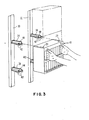
- FIG. 3 a portion of the mass storage rack is shown including vertical support members 30 and 32.
- Flanges 34, 36, 38 and 40 are fastened onto vertical support members 30 and 32.
- Flanges 34, 36, 38 and 40 which are T-shaped in cross section are spaced an appropriate distance such that the carrier may be fitted between the flanges.
- the lower surface of the flanges contain leaf springs 42 while the upper surfaces, on each side of the vertical portion of the flange, contain bosses 44.
- FIGS. 4, 5 and 6 illustrate in sequence the manner in which the carrier is moved forward, inserted and locked into the flanges 30, 32, 34 and 36.
- the flanges 34, 36, 38 and 40 include a spring and boss on the other side of the vertical portion of the T in order to accommodate another carrier. In this manner, a large number of carriers may be locked into the vertical support members to provide a mass storage array, for example, covering an entire wall or disposed in aisles.
- FIG. 7 An advantage of the carrier shown in FIG. 1 is that it may be inserted in apparatus other than the mass storage rack shown in FIG. 3.
- a movable cart is shown including a vertical support member 46 on which are mounted a plurality of flanges 48 similar to flanges 34, 36, 38 and 40 of FIG. 3.
- the carriers are placed in the flanges in the same fashion as described relative to FIG. 3 and are retained by springs and bosses within the apertures 20, 22, 24 and 26 of the carrier.
- the cart of FIG. 7 further includes wheels and handles so it may be readily moved about.
- a user could enter the mass storage area, remove selected carriers from the mass storage racks and place them securely in the cart for transportation to another location.
- a hand-held transport into which the carrier is fitted may be provided as shown in FIG. 8.
- a unique magnetic tape cartridge carrier as shown in FIG. 1, which contains a plurality of slidably accessible tape cartridges, may be used and stored in a number of different environments including a mass storage rack having a locking scheme which cooperates with the carrier structure, a movable cart having a similar locking scheme, and a hand-held transport.
Abstract
Description
- This invention relates to a carrier for containing a plurality of tape cartridges which may be placed in a storage rack, transportation cart or carry pack and secured by a support and locking apparatus.
- Since the introduction of tapes and the like, which are disposed within cartridges, cassettes or similar containers, a number of carry cases and holders have been available in the art for receiving, supporting and storing such cassettes, cartridges or the like. Usually, such holders are for a specific purpose, for example, use as a carrying case or for storage in a stationary location such as on a shelf.
- U.S. Patent 4,293,075 issued Oct. 6, 1981 to Veralrud and entitled CABINET FOR HOLDING MAGNETIC TAPE CARTRIDGES AND CASSETTES describes a multi- shelf cabinet for storing several different types of tape units having different dimensions. The shelves are sloped from front to back and include molded sidewall steps such that endless tape cartridges, reel-to-reel cassettes and cassettes in boxes of different sizes may be retained in the cabinet by the appropriate dimensional sidewall steps.
- U.S. Patent 3,907,116 issued Sept. 23, 1975 to Wolf et al entitled CASSETTE RACK describes a holder for both boxed and unboxed magnetic reel-to-reel cassettes which also includes rearward sloping support shelves in the form of stepped sidewalls of different dimensions to retain the boxed cassettes and the smaller dimensioned unboxed cassettes.
- In the prior art, the storage units are for a single purpose, i.e., stationary storage on a shelf or in a console, or as a portable carry case. The cassettes, cartridges or the like are disposed on endwall rails or flanges and are retained in place by gravity due to rearward slope or the like. There is no positive locking feature for maintaining the cartridges or cassettes securely in the holders.
- The present invention differs from the prior art as will be seen from the following description.
- An object of the present invention is to provide a carrier for tape cartridges that may be inserted and stored in separate ones of a plurality of different storage units.
- Another object of the present invention is to provide a carrier for tape cartridges that includes a locking apparatus for maintaining the carrier securely in a storage unit.
- A further object of the present invention is to provide a carrier for tape cartridges that may be positively mounted and stored in a mass storage rack, a transportation cart or an individual carry pack.
-
- FIG. 1 is a schematic illustration of one embodiment of a tape cartridge carrier which may be securely stored in a mass storage rack, a transportation cart or an individual carry pack.
- FIG. 2 is a schematic illustration of a side view of the carrier of FIG. 1 showing the detail of a pull-tab for removing a cartridge.
- FIG. 3 is a schematic illustration showing the manner in which the carriers of FIG. 1 may be securely mounted in a mass storage rack.
- FIGS. 4, 5 and 6 are illustrations of how the carriers of FIG. 1 may be placed onto the mass storage rack of FIG. 3.
- FIG. 7 is a schematic illustration showing how the carriers of FIG. 1 may be stored in a transportation cart.
- FIG. 8 is a schematic illustration showing how the carriers of FIG. 1 may be stored in a portable carry case.
- Magnetic tapes of the type which are contained in cartridges are used in a number of industries, one in particular being associated with electronic typewriters wherein text material is stored on the tapes. In such instance the magnetic tapes are subject to being retained in storage, retrieved from storage, and periodically moved from location to location. It is desirable that a single container for such cartridges be provided which may be easily placed in and removed from bulk storage, and'which may also be used to retain the cartridges when such cartridges are moved from place to place.
- FIG. 1 illustrates a carrier for magnetic tape cartridges according to the present invention. The carrier includes top, bottom, left side and right side members which form a
rectangular frame 10. Acentre member 12 intermediate to and parallel to the top and bottom members dividesframe 10 into upper and lower compartments. A plurality of vertical members 14-1, 14-2, 14-3 ... 14-M are spaced insideframe 10 parallel to the left and right side members. Vertical members 14-1 through 14-M extend the depth offrame 10, thereby dividing the upper and lower compartments thereof into a plurality of separate recesses, the dimensions of which are predetermined to be slightly greater than the dimensions of the magnetic tape cartridges to be stored. - In each recess, at the bottom thereof, a slidable member 16-1, 16-2, 16-3 ... 16-M is disposed. Each of the members 16-1 through 16-M terminates in a right angle bend and also extends past the edge of bottom member and
centre member 12. Thus, when a magnetic tape cartridge is placed in any of the recesses, the end of appropriate slidable members 16-1 ... 16-M at the bottom of the recess is grasped and pulled in order to easily remove the desired tape cartridge from the recess. When the tape cartridge is manually replaced in the recess, it will cause the slidable member to return to the position shown in FIG. 1. - Referring to FIG. 2, a side elevation view is shown illustrating how the right angle portion of the slidable elements 16-1 through 16-M may be fitted into corresponding recesses in a
back member 18 of theelement 10. An alternative to slidable members 16-1 through 16-M having a right angle termination would be to have slidable members 16-1 through 16-M flat, but have a high friction upper surface, such as having a rubberized coating on which the magnetic cartridge would be retained during input and output movements. - A high friction strip, such as a rubber strip can be mounted along the length of the front of
shelf 12 and the front of the bottom member. The rubber strip is dimensioned to be slightly higher than the front ofshelf 12 and the front of the bottom member. - The carrier shown in FIG. 1 further includes
apertures frame 10 as shown. These apertures serve to provide a simple and rapid locking and retaining scheme whereby the carrier may be placed, along with other carriers, on a mass storage rack. - Referring to FIG. 3, a portion of the mass storage rack is shown including
vertical support members Flanges vertical support members Flanges leaf springs 42 while the upper surfaces, on each side of the vertical portion of the flange, containbosses 44. - Thus, when the carrier is moved forward in FIG. 3 it will rest on the upper surface of the
flanges flanges lower apertures flanges upper apertures flanges bottom apertures - FIGS. 4, 5 and 6 illustrate in sequence the manner in which the carrier is moved forward, inserted and locked into the
flanges - It should be noted that in FIG. 3 the
flanges - An advantage of the carrier shown in FIG. 1 is that it may be inserted in apparatus other than the mass storage rack shown in FIG. 3. Referring to FIG. 7, a movable cart is shown including a
vertical support member 46 on which are mounted a plurality offlanges 48 similar toflanges apertures - It is seen, therefore, that a total system has been described wherein a unique magnetic tape cartridge carrier as shown in FIG. 1, which contains a plurality of slidably accessible tape cartridges, may be used and stored in a number of different environments including a mass storage rack having a locking scheme which cooperates with the carrier structure, a movable cart having a similar locking scheme, and a hand-held transport.
- While the invention has been particularly shown and described with reference to a preferred embodiment thereof, it will be understood by those skilled in the art that the foregoing and other changes in form and details may be made therein without departing from the spirit and scope of the invention. For example, instead of a single
centre shelf member 12 providing upper and lower rows of enclosures, as shown in FIG. 1, a plurality of such shelves may be provided for dividing the carrier into three or more rows of enclosures.
Claims (2)
Applications Claiming Priority (2)
| Application Number | Priority Date | Filing Date | Title |
|---|---|---|---|
| US54372383A | 1983-10-20 | 1983-10-20 | |
| US543723 | 1983-10-20 |
Publications (3)
| Publication Number | Publication Date |
|---|---|
| EP0138576A2 true EP0138576A2 (en) | 1985-04-24 |
| EP0138576A3 EP0138576A3 (en) | 1986-03-05 |
| EP0138576B1 EP0138576B1 (en) | 1988-12-28 |
Family
ID=24169317
Family Applications (1)
| Application Number | Title | Priority Date | Filing Date |
|---|---|---|---|
| EP19840306931 Expired EP0138576B1 (en) | 1983-10-20 | 1984-10-11 | Magnetic type cartridge carrier |
Country Status (3)
| Country | Link |
|---|---|
| EP (1) | EP0138576B1 (en) |
| JP (1) | JPS6090167A (en) |
| DE (1) | DE3475844D1 (en) |
Cited By (7)
| Publication number | Priority date | Publication date | Assignee | Title |
|---|---|---|---|---|
| EP0207237A1 (en) * | 1985-06-19 | 1987-01-07 | Wright Line Inc. | System for storing, transporting and dispensing magnetic tape cartridges |
| WO1987000957A1 (en) * | 1985-08-02 | 1987-02-12 | Idn Inventions And Development Of Novelties Ag | System for storing magnetic tape cassettes and compact discs |
| EP0212590A2 (en) * | 1985-08-19 | 1987-03-04 | Engineered Data Products, Inc. | Tape cartridge storage system |
| EP0303274A2 (en) * | 1987-08-11 | 1989-02-15 | Engineered Data Products, Inc. | Holder for tape cartridges |
| GB2235167A (en) * | 1989-07-04 | 1991-02-27 | Thomas Mcgahon | Video cassette holder |
| GB2427511A (en) * | 2005-06-20 | 2006-12-27 | Hardigg Ind Inc | Slidably mounted rack mount frame for a transport container |
| US7762750B2 (en) | 2005-06-20 | 2010-07-27 | Hardigg Industries, Inc. | Removable rack mount frame |
Families Citing this family (2)
| Publication number | Priority date | Publication date | Assignee | Title |
|---|---|---|---|---|
| KR100268752B1 (en) * | 1991-11-20 | 2000-11-01 | 엘리자베스 라슨 | Fatty acyl-coa: fatty alcohol o-acyl transferase |
| CN108466629B (en) * | 2018-04-04 | 2019-07-02 | 朱德仲 | A kind of train has the supporter of pooling feature |
Citations (13)
| Publication number | Priority date | Publication date | Assignee | Title |
|---|---|---|---|---|
| FR1253365A (en) * | 1959-12-31 | 1961-02-10 | Device for disc storage | |
| FR2122790A5 (en) * | 1971-01-19 | 1972-09-01 | Zimmermann Jacqueline | |
| US3904259A (en) * | 1974-02-22 | 1975-09-09 | Boeing Co | Magnetic tape cassette storage containers |
| DE2647663A1 (en) * | 1976-10-21 | 1978-04-27 | Isaria Display Werbemittel Gmb | Tape cassettes display container - consists of inner and outer housing locked together with pockets in inner housing |
| US4111502A (en) * | 1976-08-24 | 1978-09-05 | Harvey Kessler | Automobile tape storage case |
| US4117931A (en) * | 1973-07-25 | 1978-10-03 | Berkman Joseph L | Case for differently sized magnetic tape enclosures |
| GB2021072A (en) * | 1978-03-17 | 1979-11-28 | St John Rumble Clive | A storage device for tape cassettes and/or cartridges |
| US4180299A (en) * | 1978-04-17 | 1979-12-25 | Tolerson Lawrence E | Carrier |
| US4231625A (en) * | 1978-12-29 | 1980-11-04 | Perez Jose L | Tape storage cabinet |
| US4293075A (en) * | 1979-10-11 | 1981-10-06 | Kustom Kreations, Inc. | Cabinet for holding magnetic tape cartridges and cassettes |
| US4339162A (en) * | 1980-02-28 | 1982-07-13 | Shape, Inc. | Video cassette storage box |
| GB2132075A (en) * | 1982-12-23 | 1984-07-04 | Pd Visual Marketing Limited | Storage cabinet for parallelpipedic articles of different sizes |
| EP0141112A1 (en) * | 1983-08-29 | 1985-05-15 | idn inventions and development of novelties ag | Storage arrangement for compact cassettes or compact discs |
Family Cites Families (3)
| Publication number | Priority date | Publication date | Assignee | Title |
|---|---|---|---|---|
| JPS5731020B2 (en) * | 1974-10-22 | 1982-07-02 | ||
| JPS5435262Y2 (en) * | 1976-09-08 | 1979-10-26 | ||
| JPS5546626U (en) * | 1978-09-18 | 1980-03-27 |
-
1984
- 1984-06-08 JP JP59116750A patent/JPS6090167A/en active Pending
- 1984-10-11 EP EP19840306931 patent/EP0138576B1/en not_active Expired
- 1984-10-11 DE DE8484306931T patent/DE3475844D1/en not_active Expired
Patent Citations (13)
| Publication number | Priority date | Publication date | Assignee | Title |
|---|---|---|---|---|
| FR1253365A (en) * | 1959-12-31 | 1961-02-10 | Device for disc storage | |
| FR2122790A5 (en) * | 1971-01-19 | 1972-09-01 | Zimmermann Jacqueline | |
| US4117931A (en) * | 1973-07-25 | 1978-10-03 | Berkman Joseph L | Case for differently sized magnetic tape enclosures |
| US3904259A (en) * | 1974-02-22 | 1975-09-09 | Boeing Co | Magnetic tape cassette storage containers |
| US4111502A (en) * | 1976-08-24 | 1978-09-05 | Harvey Kessler | Automobile tape storage case |
| DE2647663A1 (en) * | 1976-10-21 | 1978-04-27 | Isaria Display Werbemittel Gmb | Tape cassettes display container - consists of inner and outer housing locked together with pockets in inner housing |
| GB2021072A (en) * | 1978-03-17 | 1979-11-28 | St John Rumble Clive | A storage device for tape cassettes and/or cartridges |
| US4180299A (en) * | 1978-04-17 | 1979-12-25 | Tolerson Lawrence E | Carrier |
| US4231625A (en) * | 1978-12-29 | 1980-11-04 | Perez Jose L | Tape storage cabinet |
| US4293075A (en) * | 1979-10-11 | 1981-10-06 | Kustom Kreations, Inc. | Cabinet for holding magnetic tape cartridges and cassettes |
| US4339162A (en) * | 1980-02-28 | 1982-07-13 | Shape, Inc. | Video cassette storage box |
| GB2132075A (en) * | 1982-12-23 | 1984-07-04 | Pd Visual Marketing Limited | Storage cabinet for parallelpipedic articles of different sizes |
| EP0141112A1 (en) * | 1983-08-29 | 1985-05-15 | idn inventions and development of novelties ag | Storage arrangement for compact cassettes or compact discs |
Cited By (11)
| Publication number | Priority date | Publication date | Assignee | Title |
|---|---|---|---|---|
| EP0207237A1 (en) * | 1985-06-19 | 1987-01-07 | Wright Line Inc. | System for storing, transporting and dispensing magnetic tape cartridges |
| WO1987000957A1 (en) * | 1985-08-02 | 1987-02-12 | Idn Inventions And Development Of Novelties Ag | System for storing magnetic tape cassettes and compact discs |
| GB2190829A (en) * | 1985-08-02 | 1987-12-02 | Idn Invention Dev Novelties | System for storing magnetic tape cassettes and compact discs |
| EP0212590A2 (en) * | 1985-08-19 | 1987-03-04 | Engineered Data Products, Inc. | Tape cartridge storage system |
| EP0212590A3 (en) * | 1985-08-19 | 1989-01-25 | Engineered Data Products, Inc. | Tape cartridge storage system |
| EP0303274A2 (en) * | 1987-08-11 | 1989-02-15 | Engineered Data Products, Inc. | Holder for tape cartridges |
| EP0303274A3 (en) * | 1987-08-11 | 1989-12-27 | Engineered Data Products, Inc. | Holder for tape cartridges |
| GB2235167A (en) * | 1989-07-04 | 1991-02-27 | Thomas Mcgahon | Video cassette holder |
| GB2427511A (en) * | 2005-06-20 | 2006-12-27 | Hardigg Ind Inc | Slidably mounted rack mount frame for a transport container |
| GB2427511B (en) * | 2005-06-20 | 2007-10-10 | Hardigg Ind Inc | Removable rack mount frame |
| US7762750B2 (en) | 2005-06-20 | 2010-07-27 | Hardigg Industries, Inc. | Removable rack mount frame |
Also Published As
| Publication number | Publication date |
|---|---|
| EP0138576B1 (en) | 1988-12-28 |
| DE3475844D1 (en) | 1989-02-02 |
| JPS6090167A (en) | 1985-05-21 |
| EP0138576A3 (en) | 1986-03-05 |
Similar Documents
| Publication | Publication Date | Title |
|---|---|---|
| US3710900A (en) | Modular system for transporting and storing tape cartridges and cassettes | |
| US4655345A (en) | Compact disc storage unit | |
| EP0533762B1 (en) | Tape cartridge holder | |
| US3851938A (en) | Storage device | |
| US4782949A (en) | Storage module for mixed-size magnetic tape receptacles | |
| EP0138576B1 (en) | Magnetic type cartridge carrier | |
| US5253756A (en) | Container for data-storage devices | |
| US4158876A (en) | Circuit board holder | |
| US5123545A (en) | Stackable storage and dispensing rack for rectangular articles | |
| CA1203208A (en) | Storage system for either boxed or unboxed cassettes | |
| US4101027A (en) | Magazine for a plurality of recording media | |
| US4389078A (en) | Modular storage unit | |
| US4182538A (en) | Storage module for tapes | |
| US4744463A (en) | Storage display tray | |
| US7475955B2 (en) | Storage assembly for modules of varying sizes and improved shelving therefor | |
| US4782958A (en) | Tape-cartridge storage system | |
| US4913296A (en) | Storing and dispensing system | |
| US5445269A (en) | Media storage bin | |
| US5139320A (en) | Tape storage device and system | |
| US4896769A (en) | Coded storage display tray | |
| US5011241A (en) | Adjustable storage system for audio and/or video media | |
| EP0081023A1 (en) | Device for storing and dispensing magnetic tape cassettes | |
| US4518084A (en) | Storage system for either boxed or unboxed cassettes | |
| US5346298A (en) | Cartridge retaining means | |
| US5908118A (en) | Apparatus for media storage |
Legal Events
| Date | Code | Title | Description |
|---|---|---|---|
| PUAI | Public reference made under article 153(3) epc to a published international application that has entered the european phase |
Free format text: ORIGINAL CODE: 0009012 |
|
| 17P | Request for examination filed |
Effective date: 19841123 |
|
| AK | Designated contracting states |
Designated state(s): DE FR GB |
|
| PUAL | Search report despatched |
Free format text: ORIGINAL CODE: 0009013 |
|
| AK | Designated contracting states |
Kind code of ref document: A3 Designated state(s): DE FR GB |
|
| 17Q | First examination report despatched |
Effective date: 19870810 |
|
| GRAA | (expected) grant |
Free format text: ORIGINAL CODE: 0009210 |
|
| AK | Designated contracting states |
Kind code of ref document: B1 Designated state(s): DE FR GB |
|
| REF | Corresponds to: |
Ref document number: 3475844 Country of ref document: DE Date of ref document: 19890202 |
|
| ET | Fr: translation filed | ||
| PLBE | No opposition filed within time limit |
Free format text: ORIGINAL CODE: 0009261 |
|
| STAA | Information on the status of an ep patent application or granted ep patent |
Free format text: STATUS: NO OPPOSITION FILED WITHIN TIME LIMIT |
|
| 26N | No opposition filed | ||
| PGFP | Annual fee paid to national office [announced via postgrant information from national office to epo] |
Ref country code: GB Payment date: 19910923 Year of fee payment: 8 |
|
| PGFP | Annual fee paid to national office [announced via postgrant information from national office to epo] |
Ref country code: FR Payment date: 19911001 Year of fee payment: 8 |
|
| PGFP | Annual fee paid to national office [announced via postgrant information from national office to epo] |
Ref country code: DE Payment date: 19911102 Year of fee payment: 8 |
|
| PG25 | Lapsed in a contracting state [announced via postgrant information from national office to epo] |
Ref country code: GB Effective date: 19921011 |
|
| GBPC | Gb: european patent ceased through non-payment of renewal fee |
Effective date: 19921011 |
|
| PG25 | Lapsed in a contracting state [announced via postgrant information from national office to epo] |
Ref country code: FR Effective date: 19930630 |
|
| PG25 | Lapsed in a contracting state [announced via postgrant information from national office to epo] |
Ref country code: DE Effective date: 19930701 |
|
| REG | Reference to a national code |
Ref country code: FR Ref legal event code: ST |