EP0138498B1 - Cutting tool - Google Patents
Cutting tool Download PDFInfo
- Publication number
- EP0138498B1 EP0138498B1 EP84306696A EP84306696A EP0138498B1 EP 0138498 B1 EP0138498 B1 EP 0138498B1 EP 84306696 A EP84306696 A EP 84306696A EP 84306696 A EP84306696 A EP 84306696A EP 0138498 B1 EP0138498 B1 EP 0138498B1
- Authority
- EP
- European Patent Office
- Prior art keywords
- insert
- cutting
- holder
- jaws
- Prior art date
- Legal status (The legal status is an assumption and is not a legal conclusion. Google has not performed a legal analysis and makes no representation as to the accuracy of the status listed.)
- Expired - Lifetime
Links
Images

Classifications
-
- B—PERFORMING OPERATIONS; TRANSPORTING
- B23—MACHINE TOOLS; METAL-WORKING NOT OTHERWISE PROVIDED FOR
- B23B—TURNING; BORING
- B23B27/00—Tools for turning or boring machines; Tools of a similar kind in general; Accessories therefor
- B23B27/14—Cutting tools of which the bits or tips or cutting inserts are of special material
- B23B27/16—Cutting tools of which the bits or tips or cutting inserts are of special material with exchangeable cutting bits or cutting inserts, e.g. able to be clamped
-
- B—PERFORMING OPERATIONS; TRANSPORTING
- B23—MACHINE TOOLS; METAL-WORKING NOT OTHERWISE PROVIDED FOR
- B23B—TURNING; BORING
- B23B27/00—Tools for turning or boring machines; Tools of a similar kind in general; Accessories therefor
- B23B27/04—Cutting-off tools
- B23B27/045—Cutting-off tools with chip-breaking arrangements
-
- B—PERFORMING OPERATIONS; TRANSPORTING
- B23—MACHINE TOOLS; METAL-WORKING NOT OTHERWISE PROVIDED FOR
- B23B—TURNING; BORING
- B23B2205/00—Fixation of cutting inserts in holders
- B23B2205/02—Fixation using an elastically deformable clamping member
-
- B—PERFORMING OPERATIONS; TRANSPORTING
- B23—MACHINE TOOLS; METAL-WORKING NOT OTHERWISE PROVIDED FOR
- B23B—TURNING; BORING
- B23B2260/00—Details of constructional elements
- B23B2260/078—Hand tools used to operate chucks or to assemble, adjust or disassemble tools or equipment used for turning, boring or drilling
- B23B2260/0785—Hand tools used to operate chucks or to assemble, adjust or disassemble tools or equipment used for turning, boring or drilling for unclamping cutting inserts
-
- Y—GENERAL TAGGING OF NEW TECHNOLOGICAL DEVELOPMENTS; GENERAL TAGGING OF CROSS-SECTIONAL TECHNOLOGIES SPANNING OVER SEVERAL SECTIONS OF THE IPC; TECHNICAL SUBJECTS COVERED BY FORMER USPC CROSS-REFERENCE ART COLLECTIONS [XRACs] AND DIGESTS
- Y10—TECHNICAL SUBJECTS COVERED BY FORMER USPC
- Y10T—TECHNICAL SUBJECTS COVERED BY FORMER US CLASSIFICATION
- Y10T407/00—Cutters, for shaping
- Y10T407/22—Cutters, for shaping including holder having seat for inserted tool
- Y10T407/2212—Cutters, for shaping including holder having seat for inserted tool with tool ejector
-
- Y—GENERAL TAGGING OF NEW TECHNOLOGICAL DEVELOPMENTS; GENERAL TAGGING OF CROSS-SECTIONAL TECHNOLOGIES SPANNING OVER SEVERAL SECTIONS OF THE IPC; TECHNICAL SUBJECTS COVERED BY FORMER USPC CROSS-REFERENCE ART COLLECTIONS [XRACs] AND DIGESTS
- Y10—TECHNICAL SUBJECTS COVERED BY FORMER USPC
- Y10T—TECHNICAL SUBJECTS COVERED BY FORMER US CLASSIFICATION
- Y10T407/00—Cutters, for shaping
- Y10T407/22—Cutters, for shaping including holder having seat for inserted tool
- Y10T407/2272—Cutters, for shaping including holder having seat for inserted tool with separate means to fasten tool to holder
- Y10T407/2282—Cutters, for shaping including holder having seat for inserted tool with separate means to fasten tool to holder including tool holding clamp and clamp actuator
- Y10T407/2286—Resiliently biased clamp jaw
- Y10T407/2288—Integral with holder
-
- Y—GENERAL TAGGING OF NEW TECHNOLOGICAL DEVELOPMENTS; GENERAL TAGGING OF CROSS-SECTIONAL TECHNOLOGIES SPANNING OVER SEVERAL SECTIONS OF THE IPC; TECHNICAL SUBJECTS COVERED BY FORMER USPC CROSS-REFERENCE ART COLLECTIONS [XRACs] AND DIGESTS
- Y10—TECHNICAL SUBJECTS COVERED BY FORMER USPC
- Y10T—TECHNICAL SUBJECTS COVERED BY FORMER US CLASSIFICATION
- Y10T407/00—Cutters, for shaping
- Y10T407/24—Cutters, for shaping with chip breaker, guide or deflector
- Y10T407/245—Cutters, for shaping with chip breaker, guide or deflector comprising concave surface in cutting face of tool
-
- Y—GENERAL TAGGING OF NEW TECHNOLOGICAL DEVELOPMENTS; GENERAL TAGGING OF CROSS-SECTIONAL TECHNOLOGIES SPANNING OVER SEVERAL SECTIONS OF THE IPC; TECHNICAL SUBJECTS COVERED BY FORMER USPC CROSS-REFERENCE ART COLLECTIONS [XRACs] AND DIGESTS
- Y10—TECHNICAL SUBJECTS COVERED BY FORMER USPC
- Y10T—TECHNICAL SUBJECTS COVERED BY FORMER US CLASSIFICATION
- Y10T407/00—Cutters, for shaping
- Y10T407/25—Cutters, for shaping including cut off tool
Definitions
- the present invention relates to a cutting insert holder and in particular to a parting-off tool having a removable insert. More particularly, the invention is concerned with a parting-off tool in which the insert is retained securely within the parting-off tool without need for special clamping devices.
- a cutting tool e.g. a parting or groove cutting tool having a plate-like holder.
- An integral arm is adapted to clamp a cutting insert within the holder, the clamping pressure on the cutting insert resulting from bending of the arm.
- a surface on the arm presses against one face of the insert while other faces of the insert engage surfaces on the holder.
- the insert may be released from or inserted into the holder when the arm is urged away from the insert by inserting an elliptical section rod in a slot portion.
- the elliptical section rod acts as a cam on turning which opens the arm and reduces pressure against the face of the insert.
- the problem with a groove cutting tool of this type is that the clamping pressure results solely from the bending of the arm. During groove cutting, extreme forces are applied to the insert which causes the arm to open allowing the insert to move within the holder.
- GB 2064390A describes a rotary cutting tool using a cutting element peripherally disposed on a disc. Each of the cutting elements frictionally engages the surface in the disc formed in a "V" shape.
- a problem with cutting tools of this type is that the jaws retaining the cutting insert are opened by the forces on the insert pushing the cutting insert into the "V". Whilst this may not be significant on a rotary saw which is constantly advancing, it cause problems in fine machine grooving and parting off.
- GB 2082485 describes a cut-off tool having a support blade with upper and lower jaws shaped for receiving an insert.
- the upper jaw 108 is flexible and provides the clamping means on the insert.
- a second aperture is positioned in the support blade such that the upper jaw is bound by the upper apertures and remains flexible.
- An actuating member is mounted in an opening which communicates with the second aperture such that a camming action causes the upper jaw to clamp the top surface of the insert.
- Cutting inserts are retained in a holder for rotary tools in U.K. Patent Application No. 2110136A and in European Patent Application 0059602, by the geometrical characteristics of the holder and the insert, by means appearing identical to the retention system disclosed in U.K. Patent Application No. 2064390A.
- the holder includes jaw-like seats for the inserts wherein the contour of the seat matches the contour of the tool holder, and there is no clamping means requiring a minimum thickness of the holder or taking up valulable space on the periphery of the tool.
- the geometry which is responsible for retaining the cutting insert in the holder in these prior art devices includes the substantially wedge shape of the inserts with prismatic or multiple plane retaining surfaces and the matching wedge shaped surfaces, respectively, of the seats.
- the inserts are located in the seats in the tool holder by means of an insertion force, and the inserts are not retained by external clamps, but instead by "wedge" forces.
- convex/concave or concave/con- vex shapes of the retaining surfaces of the seats and the inserts may provide some stability of the insert in the tool with respect to side forces, it is desirable to improve the stability to all forces and to simplify the means for retaining inserts in blades for cutting tools.
- FR 2101723 discloses a parting-off or grooving tool having a partially curved insert located by tongue and groove action. Some clamping action is provided by a locating screw. The arrangement disclosed in FR 2101723 is likely to suffer from the problem of cutting forces lifting the insert from the retaining surfaces of the seat.
- Document FR-A-2483820 discloses a cutting insert holder and cutting insert used for grooving, the holder comprising
- the present invention attempts to overcome the problems of the prior art by providing a device which can locate and clamp securely a cutting insert in a parting-off or grooving tool.
- a cutting insert holder and cutting insert used for grooving the holder comprising
- a parting tool 10 has a blade 12 in the form of a planar support blade having plane parallel faces.
- a pocket 14 at each end of the blade 12 receives an insert 16.
- One planar surface of the blade 12 is connected by a web 18, leaving the other of the plane parallel surfaces open.
- the pocket 14 has two jaws, an upper jaw 20 and a lower jaw 22 which are tapered or V-shaped away from the leading edge 24 of the blade 12.
- the upper and lower jaws 20 and 22 may taper to a fine point forming an actual "V", it is preferred that the taper finishes in an aperture 26.
- the aperture 26 is preferably circular and passes perpendicularly through the planar surfaces of the blade 12.
- the blade 12 is bound by two parallel edges, an upper edge 28 and a lower edge 30.
- the blade 12 is of relatively narrow thickness and extends to a leading edge 24 which may be obtuse in angle when referred to the base edge 30.
- the leuding edge 24 extends to the lower jaw 22 and via the web 18 to the upper jaw 20.
- An edge 32 extends from the upper jaw 20 to the top surface 28. The edge 32 is set back from the jaw 20 to allow operating clearance for the insert 16 for removal of the chips during a grooving or parting off operation.
- the web 18 extends between the upper jaw 20 and the lower jaw 22 connecting the planar side 34 of the blade 12, leaving the jaws 20, 22 open on the planar side 36.
- the web 18 needs to be as thick as possible.
- the insert also needs to be as thick as possible.
- the thickness of the web 18 is such that it provides sufficient strength between the jaws 20 and 22 to prevent the jaws from being pressed apart.
- the web is as narrow as possible to allow the insert 16 to retain its maximum strength. Whilst not being bound by any specific dimensions for the present invention, the thickness of the blade 12 between the planar sides 34, 36 is preferably from about 4 to 8 times as thick as the web 18.
- the web 18 prevents the insert 16 from being laterally ejected from the jaws 20,22 on the planar side 34 of the tool-holder 12.
- the dovetail pocket 14 prevents the insert 16 from being ejected on the opposite side.
- Figures 3 to 5 show the insert which may be used with the tool-holder of the present invention.
- the shape of the insert 16 is such that it co-operates with the tool-holder.
- the insert 16 has cutting edge 38 on insert cutting portion 40, the cutting portion 40 being substantially the same width as the blade 12.
- the cutting edge 38 is wider than the width of the blade 12.
- the cutting edge portion 40 extends from the seat portion 42 which co-operates, when in position, with the upper and lower jaws 22 and the web 18.
- the width of the seat portion 42 is less than the cutting edge portion 40.
- the two portions having a rebate 44 between them.
- This rebate allows the width of the seat portion 42 to accommodate the web and to increase to the width of the cutting portion 40.
- the cutting portion 40 when viewed as in Figure 3, can be seen to increase in width from the rebate 44 to the cutting edge 38 such that the cutting edge 38 is wider than the width of the tool-holder.
- a cutting tool arrangement comprising, a blade having at least one leading edge surface located between planar sides 34 and 36 in Figure 2 and two opposite plane parallel side faces 34 and 36 with at least one aperture, recess or pocket 14 having upper and lower jaws 20 and 22 for the retention of an insert 16, the jaws 20 and 22 being separated at one plane parallel side face 34 by a web 18, the upper and lower jaws 20 and 22 being shaped to receive and prevent lateral movement of the insert 16 when retained by the jaws 20 and 22, and an insert 16 positioned in the aperture, recess or pocket 14, the insert 16 having on one end a seat portion as shown in Figure 3, and having walls which correspond to the geometrical configuration of the upper and lower jaws 20 and 22 and the web 18 of thd blade 12, and on the other end of the insert 16 a cutting portion 40 having a cutting edge 38.
- aperture, recess or pocket 14 is tapered or V-shaped away from the leading edge 24 of blade 12 with the wider portion of the aperture, recess or
- a chip-breaker groove 46 of conventional type Whilst a specific chip breaker groove has been shown in Figure 3,4 and 5, this is not an essential feature and can be omitted or be of a different type, depending on the use of the parting-off tool.
- the chip-breaker of the type shown causes the metal which has been cut to curl and break.
- the parting-off tool has been defined, in particular with reference to a single insert, the parting-off tool may be constructed for such a single insert alone or be two-ended, such that it may be reversed and a second insert be applied to the workpiece as is shown in Figures 1 and 6.
- the dovetailed insert 16 is positioned between the upper jaws 20 and 22, abutting the web 18 of the blade 12.
- the blade 12 is clamped into the machine tool.
- the forces applied to the cutting edge 38 cause the insert to be gripped between the jaws 20 and 22. Becuuse these jaws 20 and 22 are tapered, they retain the insert in static position along the longituinal axis of the blade 12.
- the dovetail arrangement of the jaws 20, 22 in conjunction with the web 18, provide lateral positioning of the insert 16. Because there is no specific clamping device, such as a locating screw, clamp etc., the insert 16 after use is easily removed by passing the small rod through the aperture 26 forcing the insert 16 from the jaws 20, 22.
- a range of inserts 16 may be provided with different widths of cutting edges 38 for a specific blade 12. Alternatively, different sizes of inserts 16 may be provided for different sizes of blades 12.
- the tapered seat for the insert between the jaws 20 and 22, and abutting the web 18, locates the insert securely.
- the web 18 prevents the jaws 20, 22 from being forced apart under the machine forces.
- the web 18 between the jaws 20 and 22 stiffens the top part of the jaw 20 and prevents any lateral movement during machining.
Abstract
Description
- The present invention relates to a cutting insert holder and in particular to a parting-off tool having a removable insert. More particularly, the invention is concerned with a parting-off tool in which the insert is retained securely within the parting-off tool without need for special clamping devices.
- Parting-off tools using removable inserts are well known. In particular, GB 1379637 describes a cutting tool e.g. a parting or groove cutting tool having a plate-like holder. An integral arm is adapted to clamp a cutting insert within the holder, the clamping pressure on the cutting insert resulting from bending of the arm. A surface on the arm presses against one face of the insert while other faces of the insert engage surfaces on the holder. The insert may be released from or inserted into the holder when the arm is urged away from the insert by inserting an elliptical section rod in a slot portion. The elliptical section rod acts as a cam on turning which opens the arm and reduces pressure against the face of the insert. The problem with a groove cutting tool of this type is that the clamping pressure results solely from the bending of the arm. During groove cutting, extreme forces are applied to the insert which causes the arm to open allowing the insert to move within the holder.
- GB 2064390A describes a rotary cutting tool using a cutting element peripherally disposed on a disc. Each of the cutting elements frictionally engages the surface in the disc formed in a "V" shape. A problem with cutting tools of this type is that the jaws retaining the cutting insert are opened by the forces on the insert pushing the cutting insert into the "V". Whilst this may not be significant on a rotary saw which is constantly advancing, it cause problems in fine machine grooving and parting off.
- GB 2082485 describes a cut-off tool having a support blade with upper and lower jaws shaped for receiving an insert. The upper jaw 108 is flexible and provides the clamping means on the insert. A second aperture is positioned in the support blade such that the upper jaw is bound by the upper apertures and remains flexible. An actuating member is mounted in an opening which communicates with the second aperture such that a camming action causes the upper jaw to clamp the top surface of the insert. This solution overcomes some of the problems which are posed by GB 1379637. However, movement of the actuating member can cause shifting of the clamping member on the insert particularly if the actuating member becomes worn or is badly fitted into the cutting tool.
- Cutting inserts are retained in a holder for rotary tools in U.K. Patent Application No. 2110136A and in European Patent Application 0059602, by the geometrical characteristics of the holder and the insert, by means appearing identical to the retention system disclosed in U.K. Patent Application No. 2064390A. The holder includes jaw-like seats for the inserts wherein the contour of the seat matches the contour of the tool holder, and there is no clamping means requiring a minimum thickness of the holder or taking up valulable space on the periphery of the tool. The geometry which is responsible for retaining the cutting insert in the holder in these prior art devices, includes the substantially wedge shape of the inserts with prismatic or multiple plane retaining surfaces and the matching wedge shaped surfaces, respectively, of the seats. In these prior art patent application, the inserts are located in the seats in the tool holder by means of an insertion force, and the inserts are not retained by external clamps, but instead by "wedge" forces. Although convex/concave or concave/con- vex shapes of the retaining surfaces of the seats and the inserts may provide some stability of the insert in the tool with respect to side forces, it is desirable to improve the stability to all forces and to simplify the means for retaining inserts in blades for cutting tools.
- Similar considerations apply to FR 2101723 which discloses a parting-off or grooving tool having a partially curved insert located by tongue and groove action. Some clamping action is provided by a locating screw. The arrangement disclosed in FR 2101723 is likely to suffer from the problem of cutting forces lifting the insert from the retaining surfaces of the seat.
- Document FR-A-2483820 discloses a cutting insert holder and cutting insert used for grooving, the holder comprising
- a) opppsed faces;
- b) one pocket in one of said faces capable of receiving and retaining a cutting insert, said pocket comprising upper and lower surfaces forming a tapered opening adapted to wedgingly engage the cutting insert; and
- c) a web forming part of the other said faces and extending between the upper and lower surfaces of the pocket, the upper and lower surfaces having a dove tail, lateral movement of the insert thereby being prevented.
- The present invention attempts to overcome the problems of the prior art by providing a device which can locate and clamp securely a cutting insert in a parting-off or grooving tool.
- According to the present invention, there is provided a cutting insert holder and cutting insert used for grooving the holder comprising
- a) opposed parallel faces;
- b) at least one pocket in one of said faces capable of receiving and retaining a cutting insert, said pocket comprising upper and lower surfaces forming a tapered opening adapted to wedgingly engage the cutting insert; and
- c) a web forming part of the other said parallel faces and extending between the upper and lower surfaces of the pocket, the upper and lower surfaces having a dovetail, lateral movement of the insert thereby being prevented;
- d) the insert having a cutting portion substantially the same width as the holder.
- An embodiment of the present invention will be further described, by way of example only, with reference to the accompanying drawings, in which:
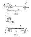
- Figure 1 is a side view of a tool-holder and cutting insert;
- Figure 2 is an axial view of the cutting insert along the line 2-2 of Figure 1;
- Figure 3 is a top view of the cutting insert suitable for the tool-holder of the arrangement shown in Figure 2;
- Figure 4 is a side view of the cutting insert;
- Figure 5 is a top view of the cutting insert; and
- Figure 6 is a perspective view of the toolholder of the present invention with the cutting insert in its operative position.
- Referring to the Figures, the same reference numerals are used for the same component or portion of the apparatus depicted in each of the Figures.
- A
parting tool 10 has ablade 12 in the form of a planar support blade having plane parallel faces. Apocket 14 at each end of theblade 12 receives aninsert 16. One planar surface of theblade 12 is connected by aweb 18, leaving the other of the plane parallel surfaces open. Thepocket 14 has two jaws, anupper jaw 20 and alower jaw 22 which are tapered or V-shaped away from the leadingedge 24 of theblade 12. Although the upper andlower jaws aperture 26. Theaperture 26 is preferably circular and passes perpendicularly through the planar surfaces of theblade 12. - The
blade 12 is bound by two parallel edges, anupper edge 28 and alower edge 30. Theblade 12 is of relatively narrow thickness and extends to a leadingedge 24 which may be obtuse in angle when referred to thebase edge 30. Theleuding edge 24 extends to thelower jaw 22 and via theweb 18 to theupper jaw 20. Anedge 32 extends from theupper jaw 20 to thetop surface 28. Theedge 32 is set back from thejaw 20 to allow operating clearance for theinsert 16 for removal of the chips during a grooving or parting off operation. - With particular reference to Figure 2, the
web 18 extends between theupper jaw 20 and thelower jaw 22 connecting the planar side 34 of theblade 12, leaving thejaws blade 12, theweb 18 needs to be as thick as possible. However, to provide sufficient cutting strength in theinsert 16, the insert also needs to be as thick as possible. Thus, the thickness of theweb 18 is such that it provides sufficient strength between thejaws insert 16 to retain its maximum strength. Whilst not being bound by any specific dimensions for the present invention, the thickness of theblade 12 between the planar sides 34, 36 is preferably from about 4 to 8 times as thick as theweb 18. - The
web 18 prevents theinsert 16 from being laterally ejected from thejaws holder 12. Thedovetail pocket 14 prevents theinsert 16 from being ejected on the opposite side. - Figures 3 to 5 show the insert which may be used with the tool-holder of the present invention. The shape of the
insert 16 is such that it co-operates with the tool-holder. Theinsert 16 has cuttingedge 38 oninsert cutting portion 40, the cuttingportion 40 being substantially the same width as theblade 12. Thecutting edge 38 is wider than the width of theblade 12. Thecutting edge portion 40 extends from theseat portion 42 which co-operates, when in position, with the upper andlower jaws 22 and theweb 18. Thus, the width of theseat portion 42 is less than thecutting edge portion 40. The two portions having arebate 44 between them. This rebate allows the width of theseat portion 42 to accommodate the web and to increase to the width of the cuttingportion 40. The cuttingportion 40, when viewed as in Figure 3, can be seen to increase in width from therebate 44 to thecutting edge 38 such that thecutting edge 38 is wider than the width of the tool-holder. - In one specific embodiment of the present invention, there is provided a cutting tool arrangement comprising, a blade having at least one leading edge surface located between planar sides 34 and 36 in Figure 2 and two opposite plane parallel side faces 34 and 36 with at least one aperture, recess or
pocket 14 having upper andlower jaws insert 16, thejaws web 18, the upper andlower jaws insert 16 when retained by thejaws insert 16 positioned in the aperture, recess orpocket 14, theinsert 16 having on one end a seat portion as shown in Figure 3, and having walls which correspond to the geometrical configuration of the upper andlower jaws web 18 ofthd blade 12, and on the other end of the insert 16 a cuttingportion 40 having a cuttingedge 38. In preferred embodiments, aperture, recess orpocket 14 is tapered or V-shaped away from the leadingedge 24 ofblade 12 with the wider portion of the aperture, recess orpocket 14 being at leadingedge surface 24. - Behind the
cutting edge 38 is a chip-breaker groove 46 of conventional type. Whilst a specific chip breaker groove has been shown in Figure 3,4 and 5, this is not an essential feature and can be omitted or be of a different type, depending on the use of the parting-off tool. The chip-breaker of the type shown causes the metal which has been cut to curl and break. - Although the parting-off tool has been defined, in particular with reference to a single insert, the parting-off tool may be constructed for such a single insert alone or be two-ended, such that it may be reversed and a second insert be applied to the workpiece as is shown in Figures 1 and 6.
- In operation, the
dovetailed insert 16 is positioned between theupper jaws web 18 of theblade 12. Theblade 12 is clamped into the machine tool. The forces applied to thecutting edge 38 cause the insert to be gripped between thejaws jaws blade 12. The dovetail arrangement of thejaws web 18, provide lateral positioning of theinsert 16. Because there is no specific clamping device, such as a locating screw, clamp etc., theinsert 16 after use is easily removed by passing the small rod through theaperture 26 forcing theinsert 16 from thejaws inserts 16 may be provided with different widths of cuttingedges 38 for aspecific blade 12. Alternatively, different sizes ofinserts 16 may be provided for different sizes ofblades 12. - The tapered seat for the insert between the
jaws web 18, locates the insert securely. Theweb 18 prevents thejaws web 18 between thejaws jaw 20 and prevents any lateral movement during machining. Although it is important to have a taper angle for theinsert 16 to form substantially V-shaped upper andlower jaws web 18, the criticality of the form, shape and angle are eliminated.
Claims (4)
Priority Applications (1)
| Application Number | Priority Date | Filing Date | Title |
|---|---|---|---|
| AT84306696T ATE56899T1 (en) | 1983-10-03 | 1984-10-01 | CUTTING TOOL. |
Applications Claiming Priority (2)
| Application Number | Priority Date | Filing Date | Title |
|---|---|---|---|
| GB08326441A GB2147528A (en) | 1983-10-03 | 1983-10-03 | Cutting tool |
| GB8326441 | 1983-10-03 |
Publications (3)
| Publication Number | Publication Date |
|---|---|
| EP0138498A2 EP0138498A2 (en) | 1985-04-24 |
| EP0138498A3 EP0138498A3 (en) | 1986-03-05 |
| EP0138498B1 true EP0138498B1 (en) | 1990-09-26 |
Family
ID=10549617
Family Applications (1)
| Application Number | Title | Priority Date | Filing Date |
|---|---|---|---|
| EP84306696A Expired - Lifetime EP0138498B1 (en) | 1983-10-03 | 1984-10-01 | Cutting tool |
Country Status (10)
| Country | Link |
|---|---|
| US (1) | US4668132A (en) |
| EP (1) | EP0138498B1 (en) |
| JP (1) | JPS60146603A (en) |
| KR (1) | KR850003692A (en) |
| AT (1) | ATE56899T1 (en) |
| AU (1) | AU3348284A (en) |
| CA (1) | CA1243194A (en) |
| DE (1) | DE3483299D1 (en) |
| ES (1) | ES290197Y (en) |
| GB (1) | GB2147528A (en) |
Families Citing this family (17)
| Publication number | Priority date | Publication date | Assignee | Title |
|---|---|---|---|---|
| SE452713B (en) * | 1986-04-07 | 1987-12-14 | Sandvik Ab | CUTTING TOOLS AND SHOULD BE USED IN THESE TOOLS |
| JPS63154101U (en) * | 1987-03-30 | 1988-10-11 | ||
| JPS63154102U (en) * | 1987-03-30 | 1988-10-11 | ||
| DE3864075D1 (en) * | 1987-05-20 | 1991-09-12 | Sumitomo Electric Industries | PARTING TOOL. |
| US5037249A (en) * | 1987-09-04 | 1991-08-06 | Kennametal Inc. | Cutting insert with chip control |
| US5088862A (en) * | 1987-09-04 | 1992-02-18 | Kennametal Inc. | Cutting insert with chip control |
| US4834592A (en) * | 1987-09-04 | 1989-05-30 | Kennametal Inc. | Cutting insert with chip control |
| AU605842B2 (en) * | 1988-03-22 | 1991-01-24 | Barend Johannes Liebenberg | Cutting tool |
| US4957396A (en) * | 1988-09-30 | 1990-09-18 | Kennametal Inc. | Cutting insert with chip control |
| DE3907922A1 (en) * | 1989-03-11 | 1990-04-26 | Zinner Gmbh Praezisionswerkzeu | MILLING TOOL |
| US5704737A (en) * | 1995-04-20 | 1998-01-06 | Kennametal Inc. | Cutting insert with chip control |
| DE69802998T2 (en) * | 1997-03-27 | 2002-07-18 | Sandvik Ab | Grooving and parting tool |
| SE511717C2 (en) * | 1997-05-22 | 1999-11-15 | Sandvik Ab | Holder for turning operations |
| SE516184C2 (en) * | 1999-07-15 | 2001-11-26 | Sandvik Ab | Clamping arrangement containing a holder blade |
| USD836143S1 (en) * | 2017-11-30 | 2018-12-18 | Illinois Tool Works Inc. | Cutting insert holder |
| USD880547S1 (en) | 2017-11-30 | 2020-04-07 | Illinois Tool Works Inc. | Cutting insert |
| USD912708S1 (en) | 2017-11-30 | 2021-03-09 | Illinois Tool Works Inc. | Cutting insert |
Family Cites Families (14)
| Publication number | Priority date | Publication date | Assignee | Title |
|---|---|---|---|---|
| FR1069769A (en) * | 1951-12-28 | 1954-07-13 | Gereedschappenfabriek Rabenhau | Tool holder with replaceable tool and tool accessory set |
| GB790805A (en) * | 1954-12-07 | 1958-02-19 | Georg Hufnagel | Improvements relating to tools comprising hard-metal cutting bodies |
| GB1254578A (en) * | 1969-07-04 | 1971-11-24 | Wickman Wimet Ltd | Milling cutters |
| US3660877A (en) * | 1970-04-22 | 1972-05-09 | Warner Swasey Co | Cutoff tool having improved cutting tip |
| GB1345336A (en) * | 1970-08-15 | 1974-01-30 | Taper Tip Ltd | Metal cutting tools |
| SE368785B (en) * | 1971-03-01 | 1974-07-22 | Sandvik Ab | |
| US3748710A (en) * | 1971-09-20 | 1973-07-31 | F Lynch | Tool bit holder |
| US3780408A (en) * | 1972-03-02 | 1973-12-25 | Kennametal Inc | Cutting tool |
| US4195956A (en) * | 1978-08-01 | 1980-04-01 | Wlajko Mihic | Slotting tool with exchangeable cutting insert |
| US4202651A (en) * | 1978-10-30 | 1980-05-13 | St Jean William A | Lathe tool holder |
| US4417833A (en) * | 1979-12-04 | 1983-11-29 | Iscar Ltd. | Rotary slot cutting tools |
| DE3021314C2 (en) * | 1980-06-06 | 1986-04-10 | TechnoARBED Deutschland GmbH, 6600 Saarbrücken | Parting and grooving tool |
| US4357123A (en) * | 1980-08-28 | 1982-11-02 | The Valeron Corporation | Insert retention apparatus |
| IL62278A (en) * | 1981-03-03 | 1984-10-31 | Iscar Ltd | Rotational cutting tool |
-
1983
- 1983-10-03 GB GB08326441A patent/GB2147528A/en not_active Withdrawn
-
1984
- 1984-09-25 AU AU33482/84A patent/AU3348284A/en not_active Abandoned
- 1984-09-27 CA CA000464166A patent/CA1243194A/en not_active Expired
- 1984-10-01 EP EP84306696A patent/EP0138498B1/en not_active Expired - Lifetime
- 1984-10-01 DE DE8484306696T patent/DE3483299D1/en not_active Expired - Lifetime
- 1984-10-01 AT AT84306696T patent/ATE56899T1/en active
- 1984-10-02 KR KR1019840006092A patent/KR850003692A/en not_active Application Discontinuation
- 1984-10-03 ES ES1984290197U patent/ES290197Y/en not_active Expired
- 1984-10-03 JP JP59206447A patent/JPS60146603A/en active Pending
-
1986
- 1986-07-11 US US06/884,886 patent/US4668132A/en not_active Expired - Fee Related
Also Published As
| Publication number | Publication date |
|---|---|
| ATE56899T1 (en) | 1990-10-15 |
| EP0138498A2 (en) | 1985-04-24 |
| GB2147528A (en) | 1985-05-15 |
| ES290197Y (en) | 1986-10-16 |
| EP0138498A3 (en) | 1986-03-05 |
| DE3483299D1 (en) | 1990-10-31 |
| GB8326441D0 (en) | 1983-11-02 |
| AU3348284A (en) | 1985-04-18 |
| CA1243194A (en) | 1988-10-18 |
| US4668132A (en) | 1987-05-26 |
| JPS60146603A (en) | 1985-08-02 |
| ES290197U (en) | 1986-03-01 |
| KR850003692A (en) | 1985-06-26 |
Similar Documents
| Publication | Publication Date | Title |
|---|---|---|
| EP0138498B1 (en) | Cutting tool | |
| US4357123A (en) | Insert retention apparatus | |
| KR100272500B1 (en) | Cutting tool with insert clamping mechanism | |
| EP0851796B1 (en) | Cutting tool with insert clamping mechanism | |
| US5921724A (en) | Insert and toolholder for machining operations | |
| EP1345723B1 (en) | Cutting tool | |
| EP1159101B1 (en) | Toolholder with detachable blade | |
| EP1013364B1 (en) | Cutting tool assembly | |
| EP1918052B1 (en) | Cutting insert as well as combination of a cutting insert and an insert holder | |
| US6234727B1 (en) | Resilient clamping mechanism for inserts | |
| EP0152729B1 (en) | Chip cutting tool | |
| US4443136A (en) | Machine cutting tool | |
| US5947648A (en) | Toolholder assembly | |
| US4738570A (en) | Rotary slot cutting tools | |
| US7331736B2 (en) | Metal cutting tool | |
| SU1720804A1 (en) | Cutting tool | |
| EP0205886A2 (en) | Improvements in or relating to an end milling cutter | |
| KR200232347Y1 (en) | Wedge-type holder for fixing a cutting insert which has a rear support surface | |
| CS246611B1 (en) | Cutting tool |
Legal Events
| Date | Code | Title | Description |
|---|---|---|---|
| PUAI | Public reference made under article 153(3) epc to a published international application that has entered the european phase |
Free format text: ORIGINAL CODE: 0009012 |
|
| AK | Designated contracting states |
Designated state(s): AT BE CH DE FR GB IT LI NL SE |
|
| PUAL | Search report despatched |
Free format text: ORIGINAL CODE: 0009013 |
|
| AK | Designated contracting states |
Kind code of ref document: A3 Designated state(s): AT BE CH DE FR GB IT LI NL SE |
|
| 17P | Request for examination filed |
Effective date: 19860826 |
|
| 17Q | First examination report despatched |
Effective date: 19870908 |
|
| RAP1 | Party data changed (applicant data changed or rights of an application transferred) |
Owner name: CARBOLOY INC. |
|
| GRAA | (expected) grant |
Free format text: ORIGINAL CODE: 0009210 |
|
| AK | Designated contracting states |
Kind code of ref document: B1 Designated state(s): AT BE CH DE FR GB IT LI NL SE |
|
| PG25 | Lapsed in a contracting state [announced via postgrant information from national office to epo] |
Ref country code: SE Effective date: 19900926 Ref country code: NL Effective date: 19900926 Ref country code: LI Effective date: 19900926 Ref country code: IT Free format text: LAPSE BECAUSE OF FAILURE TO SUBMIT A TRANSLATION OF THE DESCRIPTION OR TO PAY THE FEE WITHIN THE PRESCRIBED TIME-LIMIT;WARNING: LAPSES OF ITALIAN PATENTS WITH EFFECTIVE DATE BEFORE 2007 MAY HAVE OCCURRED AT ANY TIME BEFORE 2007. THE CORRECT EFFECTIVE DATE MAY BE DIFFERENT FROM THE ONE RECORDED. Effective date: 19900926 Ref country code: FR Effective date: 19900926 Ref country code: CH Effective date: 19900926 Ref country code: BE Effective date: 19900926 Ref country code: AT Effective date: 19900926 |
|
| REF | Corresponds to: |
Ref document number: 56899 Country of ref document: AT Date of ref document: 19901015 Kind code of ref document: T |
|
| REF | Corresponds to: |
Ref document number: 3483299 Country of ref document: DE Date of ref document: 19901031 |
|
| PG25 | Lapsed in a contracting state [announced via postgrant information from national office to epo] |
Ref country code: GB Effective date: 19901126 |
|
| REG | Reference to a national code |
Ref country code: CH Ref legal event code: PL |
|
| EN | Fr: translation not filed | ||
| NLV1 | Nl: lapsed or annulled due to failure to fulfill the requirements of art. 29p and 29m of the patents act | ||
| GBPC | Gb: european patent ceased through non-payment of renewal fee | ||
| PLBE | No opposition filed within time limit |
Free format text: ORIGINAL CODE: 0009261 |
|
| STAA | Information on the status of an ep patent application or granted ep patent |
Free format text: STATUS: NO OPPOSITION FILED WITHIN TIME LIMIT |
|
| 26N | No opposition filed | ||
| PGFP | Annual fee paid to national office [announced via postgrant information from national office to epo] |
Ref country code: DE Payment date: 20031009 Year of fee payment: 20 |