EP0138330B1 - Méthode et système de commande d'un panneau d'affichage à mémoire - Google Patents
Méthode et système de commande d'un panneau d'affichage à mémoire Download PDFInfo
- Publication number
- EP0138330B1 EP0138330B1 EP84305589A EP84305589A EP0138330B1 EP 0138330 B1 EP0138330 B1 EP 0138330B1 EP 84305589 A EP84305589 A EP 84305589A EP 84305589 A EP84305589 A EP 84305589A EP 0138330 B1 EP0138330 B1 EP 0138330B1
- Authority
- EP
- European Patent Office
- Prior art keywords
- sustainer
- scan
- display
- cells
- electrode
- Prior art date
- Legal status (The legal status is an assumption and is not a legal conclusion. Google has not performed a legal analysis and makes no representation as to the accuracy of the status listed.)
- Expired - Lifetime
Links
Images

Classifications
-
- G—PHYSICS
- G09—EDUCATION; CRYPTOGRAPHY; DISPLAY; ADVERTISING; SEALS
- G09G—ARRANGEMENTS OR CIRCUITS FOR CONTROL OF INDICATING DEVICES USING STATIC MEANS TO PRESENT VARIABLE INFORMATION
- G09G3/00—Control arrangements or circuits, of interest only in connection with visual indicators other than cathode-ray tubes
- G09G3/20—Control arrangements or circuits, of interest only in connection with visual indicators other than cathode-ray tubes for presentation of an assembly of a number of characters, e.g. a page, by composing the assembly by combination of individual elements arranged in a matrix no fixed position being assigned to or needed to be assigned to the individual characters or partial characters
- G09G3/22—Control arrangements or circuits, of interest only in connection with visual indicators other than cathode-ray tubes for presentation of an assembly of a number of characters, e.g. a page, by composing the assembly by combination of individual elements arranged in a matrix no fixed position being assigned to or needed to be assigned to the individual characters or partial characters using controlled light sources
- G09G3/28—Control arrangements or circuits, of interest only in connection with visual indicators other than cathode-ray tubes for presentation of an assembly of a number of characters, e.g. a page, by composing the assembly by combination of individual elements arranged in a matrix no fixed position being assigned to or needed to be assigned to the individual characters or partial characters using controlled light sources using luminous gas-discharge panels, e.g. plasma panels
- G09G3/2813—Control arrangements or circuits, of interest only in connection with visual indicators other than cathode-ray tubes for presentation of an assembly of a number of characters, e.g. a page, by composing the assembly by combination of individual elements arranged in a matrix no fixed position being assigned to or needed to be assigned to the individual characters or partial characters using controlled light sources using luminous gas-discharge panels, e.g. plasma panels using alternating current [AC] - direct current [DC] hybrid-type panels
-
- G—PHYSICS
- G09—EDUCATION; CRYPTOGRAPHY; DISPLAY; ADVERTISING; SEALS
- G09G—ARRANGEMENTS OR CIRCUITS FOR CONTROL OF INDICATING DEVICES USING STATIC MEANS TO PRESENT VARIABLE INFORMATION
- G09G3/00—Control arrangements or circuits, of interest only in connection with visual indicators other than cathode-ray tubes
- G09G3/20—Control arrangements or circuits, of interest only in connection with visual indicators other than cathode-ray tubes for presentation of an assembly of a number of characters, e.g. a page, by composing the assembly by combination of individual elements arranged in a matrix no fixed position being assigned to or needed to be assigned to the individual characters or partial characters
- G09G3/22—Control arrangements or circuits, of interest only in connection with visual indicators other than cathode-ray tubes for presentation of an assembly of a number of characters, e.g. a page, by composing the assembly by combination of individual elements arranged in a matrix no fixed position being assigned to or needed to be assigned to the individual characters or partial characters using controlled light sources
- G09G3/28—Control arrangements or circuits, of interest only in connection with visual indicators other than cathode-ray tubes for presentation of an assembly of a number of characters, e.g. a page, by composing the assembly by combination of individual elements arranged in a matrix no fixed position being assigned to or needed to be assigned to the individual characters or partial characters using controlled light sources using luminous gas-discharge panels, e.g. plasma panels
- G09G3/288—Control arrangements or circuits, of interest only in connection with visual indicators other than cathode-ray tubes for presentation of an assembly of a number of characters, e.g. a page, by composing the assembly by combination of individual elements arranged in a matrix no fixed position being assigned to or needed to be assigned to the individual characters or partial characters using controlled light sources using luminous gas-discharge panels, e.g. plasma panels using AC panels
- G09G3/297—Control arrangements or circuits, of interest only in connection with visual indicators other than cathode-ray tubes for presentation of an assembly of a number of characters, e.g. a page, by composing the assembly by combination of individual elements arranged in a matrix no fixed position being assigned to or needed to be assigned to the individual characters or partial characters using controlled light sources using luminous gas-discharge panels, e.g. plasma panels using AC panels using opposed discharge type panels
Definitions
- a new type of display panel having memory is described in U.S. patent US-A-4,386,348, dated May 31, 1983, of George E. Holz and James A. Ogle.
- the panel comprises a gas-filled envelope including a layer of D.C. scan/address cells and a layer of quasi A.C. display cells.
- the scan cells are arrayed in rows and columns, and the display cells are arrayed in corresponding rows and columns.
- the scan cells are scanned and turned on column-by-column by operation of their electrodes while sustain signals are simultaneously being applied to the display cells, and the same electrodes are used to transfer information from selected scan cells to the associated display cells where glow is sustained by the sustainer signals.
- the cells which are energized in the entire panel, by this routine display a stationary but changeable message.
- the panel In one mode of operation of these panels described and claimed in an application entitled SYSTEM AND METHOD FOR OPERATING A DISPLAY PANEL HAVING MEMORY, filed concurrently herewith by George E. Holz and James A. Ogle, the panel is operated and displays a message. Then, at some time, it is, in effect, turned off while information which is in the panel is erased or while new information is written into the panel, and then it is turned on again to display the new information. If the panel is held off for too long a time before it is turned on again, it may not come back on properly and some information may be lost.
- the present invention solves this problem, and it also permits turning off a panel having a message contained in it and then turning on the panel minutes later without losing the message. Thus, whenever cell re-ignition is required, the present invention can be employed.
- the present invention comprises an electronic system used with a display panel of the type described and claimed in the above-identified patent, which is incorporated herein by reference.
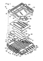
- This display panel 10 comprises a gas-filled envelope made up of an insulating base plate 20 and a glass face plate 30, which is shown tilted up and to the left in Fig. 1 to present a view of its inner surface. These plates are hermetically sealed together along their aligned perimeters to provide an envelope which encloses the various gas-filled cells and operating electrodes of the panel.
- the base plate has a top surface 22 in which a plurality of deep parallel slots 40 are formed and in each of which a scan/ address anode electrode 50 is seated and secured.
- a plurality of scan cathode electrodes 60 are seated on the top surface of the base plate or in shallow grooves 70 therein.
- the grooves 70 and scan cathodes 60 are disposed transverse to the grooves 40 and scan anodes 50, and each crossing of a scan cathode 60 and scan anode 50 defines a scanning cell 72 (Fig. 2).
- the anodes 50 and cathodes 60 form a matrix of scanning cells which are arrayed in rows and columns. More specifically, the cathode portions 61, the underlying portions of anodes 50, and the intermediate gas volumes define the scanning cells.
- the scan cathodes 60A, B, C, etc. form a series of cathodes which can be energized serially in a scanning cycle, with cathode 60A being the first cathode energized in the scanning cycle.
- a reset cathode electrode 62 is disposed on the base plate or in a groove 64 therein adjacent to the first scan cathode 60A, so that, when it is energized, it provides excited particles for cathode 60A at the beginning of a scanning cycle to be described. Where the reset cathode crosses each scan anode 50, a reset cell is formed, and the crossing of all of the scan anodes by the reset cathode provides a column of reset cells. These reset cells are turned on or energized at the beginning of each scanning cycle, and they expedite the turn-on of the first column of scanning cells associated with cathode 60A.
- the panel 10 includes a keep-alive arrangement which is described below and in U. S. Patent No. 4,329,616 of George E. Holz and James A. Ogle, which is incorporated herein by reference.
- spacer means comprising strips 74 of insulating material, such as glass, are provided on the top surface of the insulating plate 20 between slots 40 and crossing cathodes 60 and 62 so that the cathodes are spaced uniformly from an electrode plate 80 (known as the priming plate) disposed above them, as described below.
- the strips 74 are disposed across the cathodes 60 which are thus separated into the discrete operating portions 61.
- the portions of the panel described up to this point comprise the base plate assembly. This is the D.C. portion and the scanning and addressing portion of the panel 10 in which the electrodes are in contact with the gas in the panel.
- Adjacent to the base plate assembly is the second portion of the panel which is a quasi A.C. assembly; that is, it includes electrodes which are insulated from the gas in the panel, and electrodes which are in contact with the gas.
- This portion of the panel includes electrode 80 which is in the form of a thin metal plate having an array of rows and columns of relatively small apertures 92, each overlying one of the scanning cells.
- the plate 80 is positioned close to cathode 60 and may be seated on insulating strips 74. Plate 80 is known as a priming plate.
- an apertured plate 86 Adjacent to plate 80, and preferably in contact with the upper surface thereof, is an apertured plate 86 (known as the glow isolator) having rows and columns of apertures 94which are larger than apertures 92.
- the apertures 94 comprise the display cells of panel 10.
- the sheet 86 may be of insulating material, or it may be of metal, and, if it is of metal, the plates 80 and 86 may be made in one piece.
- Plate 80 is provided with a tab 88, to which external electrical contact can be made.
- the quasi A.C. assembly also includes a face plate assembly which includes a single large-area transparent conductive electrode 100 on the inner surface of the plate 30.
- a narrow conductor 110 which outlines and reinforces the electrode layer 100 in conductive contact, serves to increase its conductivity, if necessary.
- the conductor 110 includes a suitable tab 114, to which external connection can be made.
- the large-area electrode 100 is of sufficient area to overlie the entire array of display cells 94 in plate 86.
- An insulating coating 120 of glass or the like covers electrode 100, and this layer 120 is coated with a low work function refractory layer 132 of magnesium oxide, thorium oxide, or the like.
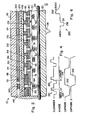
- the apertures 94 in plate 86 comprise display cells, and, as can be seen in Fig. 2, each display cell has one end wall 134 formed by a portion of insulating layer 132, and an opposite end wall 136 formed by a portion of the top surface of plate 80.
- a coating of the material of layer 132 should also be provided on the base or lower wall 136 of each display cell 94, such as the layer 133 shown in Fig. 2.
- both layer 132 and layer 133 may be formed by an evaporation process, and layer 133 may be so thin that it is not completely continuous, which is a desirable quality. In any case, however, the character of this wall of the cell is affected by the aperture 92 in the metal plate 80.
- the gas filling in panel 10 is preferably a Penning gas mixture of, for example, neon and a small percentage of xenon, at a pressure of about 400 Torr.
- the gas filling is introduced through a tubulation 24 secured to base plate 20 (Fig. 2), or a non-tubulated construction can be employed.
- the keep-alive arrangement in panel 10, includes an A.C. electrode 140 in the form of a line- like conductive film or layer of an opaque metal, such as silver, provided on the inner surface of the face plate 30 adjacent to one edge of the transparent conductive electrode 100.
- the A.C. keep-alive electrode 140 is positioned so that, in the completed panel, it overlies the column of reset cells and reset cathode 62, to which it supplies excited particles.
- the A.C. keep-alive electrode 140 is covered by the insulating layers 120 and 132.
- the plate 86 is provided with a slot 142
- plate 80 is provided with a column of holes 150.
- the slot 142 overlies and is aligned with the column of holes 150, and both lie beneath and are aligned with the A.C. electrode 140 so that, in effect, the electrode 140, slot 142 and holes 150 form a sandwich.
- the slot 142 in the plate 86 is narrower than the opaque A.C. electrode 140 so that a viewer, looking through face plate 30, cannot see any glow which is present in slot 142 and holes 150.
- Electrode 140 operates with plate 80 to produce glow discharge between them and produce excited particles in slot 142 and holes 150. These excited particles are available to the reset cathode 62 and assist the firing of the column of reset cells.
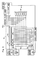
- the circuit includes a keep-alive driver 170, which provides an A.C. signal, suitably coupled to keep-alive electrode 140.
- the system also includes module 172 which comprises a series of serially energizable drivers for providing a negative reset pulse for reset cathode 62 on lead 173 and a series of negative scan cathode pulses for cathodes 60 on leads 174.
- the scan cathodes 60 are connected in groups or phases, with each group including any suitable number of cathodes such as three or four orsix, or more, as desired.
- the scan phase drivers in module 172 are sequentially activated so as to energize each of the cathodes 60 in consecutive sequence along the "X" axis of the panel.
- a D.C. power source 185 is coupled through a resistive path to each of the scan anodes 50.
- separate data drivers 183 each of which represents a source of write pulses and erase pulses, are coupled, one to each scan/address anode 50.
- a source 187 of D.C. bias potential is coupled to priming plate 80, and a source 200 of A.C. sustainer signals, is connected to the transparent conductive layer 100.
- Suitable timing and synchronizing circuits 190 are provided as required.
- the operation of display panel 10, as described in the above-identified patent 4,386,348, is generally as follows. With the keep-alive mechanism energized by source 170 and generating excited particles, and with operating potential applied to the scan anodes 50 from source 185, the reset cathode 62 is energized to fire the column of reset cells, and then the scan cathodes 60 are energized sequentially by operation of driver module 12 to carry out a scanning operation in the D.C. scan portion and scan cells 72 of the panel 10. At the same time, with A.C.
- the sustainer pulses keep these cells lit and the written message displayed.
- the erasing operation is generally similar to the writing operation described above.
- the selected display cell is operated upon while its underlying scan cell is being scanned, but the erase signal is applied in synchronism with, but following, the negative sustainer pulse.
- the associated scan cell is again turned off momentarily, and then it is turned back on, to avoid interfering with the normal column-by-column scan of the scan cells. While it is off, the decaying discharge around electrode portion 61 again produces electron flow to electrode 80, and through the aperture in that electrode into the display cell.
- a logic circuit 201 is coupled to sustainer pulse generator 200 for performing the operations described below.
- Fig. 4 shows some of the waveforms used in carrying out the foregoing operation. These waveforms include sustainer pulses 210, write and erase pulses 214 and 216, respectively, and their relationship to the sustainer pulses, and the turn-on signals 212 applied to two successive cathodes in a scanning cycle.
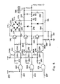
- a circuit such as that shown in Fig. 5 can be used to provide the sustainer signals 210 (Fig. 6) and other sustainer signals to be described.
- the circuit is shown in the above-cited. US-A-4,315,259 of McKee and Lee. In operation of this circuit, the turn-on pulses for the circuit 200 are controlled by appropriate logic in source 201 to obtain the desired frequency and wave shape.
- control circuit 190 operates logic circuit 201 to first apply a turn-on pulse to AND gate 206, the output of which, operating through transformer 234, turns on transistor 264.
- Transformer 234 performs signal level shifting and provides base current to turn on transistor 264 and a low base impedance to assist in the turn-off of transistor 264.
- the turn-on of transistor 264 generates the negative-going pulse 291 (Fig. 6) at lead 278 which reaches a level of about zero volts.
- AND gate 202 receives a turn-on pulse which operates through transformer 230, like transformer 234, to turn on transistor 260, and this generates current flow through the diode bridge 274 to return the sustaining pulse to the 80 volt level.
- AND gate 204 receives a turn-on pulse, and its output turns on transistor 262 which generates the positive pulse 292 of the sustaining signal to a level of about 200 volts.
- AND gate 202 receives another pulse to turn on transistor 260 again to generate the negative-going portion of the sustaining signal back to the 80 volts level by way of the diode bridge 274.
- transistor 260 performs a dual function in switching the sustaining signal either from 200 volts to the reference level of 80 volts or from zero volts to the reference level of 80 volts.
- the positive or negative transition of the switching operation of transistor 260 is determined by the sustain output voltage level prior to switching and the resultant path through the diode bridge 274. If the sustain output level is at 200 volts, the turn-on of transistor 260 will cause the sustain output to switch in a negative direction to 80 volts due to the low impedance path to the 80 volt bus 288 by way of resistors 279, diode 284, transistor 260, and diode 286. Diodes 285 and 287 are open circuited.
- the turn-on of the transistor 260 will cause the sustain level to switch in a positive direction along a low impedance path to the 80 volt bus 388 by way of resistor 279, diode 287, transistor 260, and diode 285, with diodes 284 and 286 being open circuited.
- circuit 200 can be readily operated as required to provide the sustainer pulses to be described below.
- the present invention relates particularly to a mode of operation of panel 10 wherein the panel is either turned off entirely for a period of time or it is operated at a low level of brightness for a period of time.
- One mode of operation of this type is described and claimed in the application entitled SYSTEM AND METHOD FOR OPERATING A DISPLAY PANEL HAVING MEMORY, filed concurrently herewith.
- information is written into the panel or erased while the panel is, in effect, turned off and a steady sustainer signal is applied.
- the present invention provides re-ignition of the panel without loss of information during this write or erase period.
- the display panel is displaying -information with sustainer signals being applied at a suitable frequency. Then, when information is to be written into the panel, the sustainer pulses are discontinued and a positive steady sustainer signal is applied to the entire panel (period B) to permit cells to be addressed and information to be set into the panel. During this period of time, period B, the columns of scan cells are cycled through and selected display cells are addressed and written, this operation being carried out at high speed, of about 10 milliseconds or less to minimize flicker.
- a cell re-ignition time period C is provided following the scan and address time period B, and this is followed by period D in which normal display is achieved by the application of the "normal" sustainer signals, as in period A, to retain the message set into the panel during period B.
- the sustainer signal in the re-ignition period, includes a steady negative sustainer level following the scan period B and having one sustainer pulse P, from negative to positive to negative, in the middle of the period and a similar pulse p at the end of the period.
- the cell re-ignition period has a time duration of one to four milliseconds.
- the cell re-ignition period is required in some modes of operation and for some panels, since some of the display cells which are selected during the addressing period B may not be re-ionized and turned on after the off- time of the scan time slot, period B.
- the apparent effect is the loss of some display points following each such scan period. It is believed that these re-ignition failures occur when a cell fires very late in a sustain pulse and has less opportunity, than otherwise, to accumulate wall charge before the sustain signal returns to its center or reference level, after which the already small wall charge is further depleted, thus effectively erasing the cell. Another way of viewing this result is that a late firing is similar in effect to a very short sustain pulse, a classical cell erase technique.
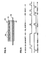
- A.C. plasma panel 290 of the type shown in Fig. 8 and comprising two spaced-apart glass plates 292 and 294, each of which carries an array of insulated electrodes, one set of electrodes 296 being disposed transverse to the other array of electrodes 298.
- the waveforms described above are split into two generally complementary portions, one applied to one set of electrodes and one applied to the other set of electrodes so that the net effect is to have the desired total voltage variations across the panel.
- Such waveforms are illustrated in Fig. 9.
Landscapes
- Engineering & Computer Science (AREA)
- Physics & Mathematics (AREA)
- Plasma & Fusion (AREA)
- Computer Hardware Design (AREA)
- General Physics & Mathematics (AREA)
- Theoretical Computer Science (AREA)
- Control Of Indicators Other Than Cathode Ray Tubes (AREA)
Claims (9)
Applications Claiming Priority (2)
| Application Number | Priority Date | Filing Date | Title |
|---|---|---|---|
| US06/525,283 US4575716A (en) | 1983-08-22 | 1983-08-22 | Method and system for operating a display panel having memory with cell re-ignition means |
| US525283 | 1983-08-22 |
Publications (3)
| Publication Number | Publication Date |
|---|---|
| EP0138330A2 EP0138330A2 (fr) | 1985-04-24 |
| EP0138330A3 EP0138330A3 (en) | 1987-08-19 |
| EP0138330B1 true EP0138330B1 (fr) | 1990-11-07 |
Family
ID=24092625
Family Applications (1)
| Application Number | Title | Priority Date | Filing Date |
|---|---|---|---|
| EP84305589A Expired - Lifetime EP0138330B1 (fr) | 1983-08-22 | 1984-08-17 | Méthode et système de commande d'un panneau d'affichage à mémoire |
Country Status (5)
| Country | Link |
|---|---|
| US (1) | US4575716A (fr) |
| EP (1) | EP0138330B1 (fr) |
| JP (1) | JPH0648429B2 (fr) |
| CA (1) | CA1233920A (fr) |
| DE (1) | DE3483556D1 (fr) |
Families Citing this family (3)
| Publication number | Priority date | Publication date | Assignee | Title |
|---|---|---|---|---|
| JP3259253B2 (ja) * | 1990-11-28 | 2002-02-25 | 富士通株式会社 | フラット型表示装置の階調駆動方法及び階調駆動装置 |
| US6097357A (en) * | 1990-11-28 | 2000-08-01 | Fujitsu Limited | Full color surface discharge type plasma display device |
| US6787995B1 (en) * | 1992-01-28 | 2004-09-07 | Fujitsu Limited | Full color surface discharge type plasma display device |
Family Cites Families (10)
| Publication number | Priority date | Publication date | Assignee | Title |
|---|---|---|---|---|
| US3919591A (en) * | 1973-06-29 | 1975-11-11 | Ibm | Gas panel with improved write-erase and sustain circuits and operations |
| US4067047A (en) * | 1976-03-29 | 1978-01-03 | Owens-Illinois, Inc. | Circuit and method for generating gray scale in gaseous discharge panels |
| CA1087768A (fr) * | 1976-12-30 | 1980-10-14 | Eugene S. Schlig | Ecriture et effacement dans des afficahges au plasma (ac) |
| JPS543328A (en) * | 1977-06-09 | 1979-01-11 | Hokkaido Nozai Kogyo Co | Method of piling blocks |
| US4386348A (en) * | 1979-06-22 | 1983-05-31 | Burroughs Corporation | Display panel having memory |
| US4378556A (en) * | 1979-12-10 | 1983-03-29 | United Technologies Corporation | Gray shade operation of sequentially addressed AC plasma panel |
| US4329616A (en) * | 1979-12-31 | 1982-05-11 | Burroughs Corporation | Keep-alive electrode arrangement for display panel having memory |
| US4315259A (en) * | 1980-10-24 | 1982-02-09 | Burroughs Corporation | System for operating a display panel having memory |
| US4373157A (en) * | 1981-04-29 | 1983-02-08 | Burroughs Corporation | System for operating a display panel |
| US4415892A (en) * | 1981-06-12 | 1983-11-15 | Interstate Electronics Corporation | Advanced waveform techniques for plasma display panels |
-
1983
- 1983-08-22 US US06/525,283 patent/US4575716A/en not_active Expired - Lifetime
-
1984
- 1984-08-10 JP JP59168731A patent/JPH0648429B2/ja not_active Expired - Lifetime
- 1984-08-15 CA CA000461059A patent/CA1233920A/fr not_active Expired
- 1984-08-17 EP EP84305589A patent/EP0138330B1/fr not_active Expired - Lifetime
- 1984-08-17 DE DE8484305589T patent/DE3483556D1/de not_active Expired - Fee Related
Also Published As
| Publication number | Publication date |
|---|---|
| JPH0648429B2 (ja) | 1994-06-22 |
| DE3483556D1 (de) | 1990-12-13 |
| US4575716A (en) | 1986-03-11 |
| EP0138330A2 (fr) | 1985-04-24 |
| CA1233920A (fr) | 1988-03-08 |
| EP0138330A3 (en) | 1987-08-19 |
| JPS6095493A (ja) | 1985-05-28 |
Similar Documents
| Publication | Publication Date | Title |
|---|---|---|
| US4063131A (en) | Slow rise time write pulse for gas discharge device | |
| US4087805A (en) | Slow rise time write pulse for gas discharge device | |
| EP0138329B1 (fr) | Système et méthode de commande d'un panneau d'affichage à mémoire | |
| US4315259A (en) | System for operating a display panel having memory | |
| US4253044A (en) | Gas discharge display panel, display apparatus comprising the panel and method of operating the display apparatus | |
| US4518894A (en) | Display panel having memory | |
| US4613854A (en) | System for operating a dot matrix display panel to prevent crosstalk | |
| EP0023082B1 (fr) | Dispositif d'affichage et methode de mise en oeuvre | |
| US4373157A (en) | System for operating a display panel | |
| US4329616A (en) | Keep-alive electrode arrangement for display panel having memory | |
| US4532505A (en) | Gas-filled dot matrix display panel | |
| EP0138330B1 (fr) | Méthode et système de commande d'un panneau d'affichage à mémoire | |
| US3921021A (en) | Display panel having memory | |
| WO1983003157A1 (fr) | Tableau d'affichage a plasma avec des colonnes uniquement de balayage | |
| Weston | Plasma panel displays | |
| US4533913A (en) | Gas-filled dot matrix display panel and operating system | |
| US3767968A (en) | Panel-type display device having display cells and auxiliary cells for operating them | |
| US4010395A (en) | Gas discharge display panel with cell-firing means having glow spreading electrode | |
| US4031429A (en) | Information display and method of operating with storage | |
| US3781587A (en) | Gas discharge display apparatus | |
| US3995185A (en) | Display panel | |
| US4047169A (en) | Display panel having improved arrangement of reset cells for facilitating scanning of the panel | |
| US4156164A (en) | Display device using hot cathode gas discharge | |
| US4065699A (en) | Cathode assembly for two-dimensional scanned gas discharge display panel | |
| USRE29858E (en) | Display panel |
Legal Events
| Date | Code | Title | Description |
|---|---|---|---|
| PUAI | Public reference made under article 153(3) epc to a published international application that has entered the european phase |
Free format text: ORIGINAL CODE: 0009012 |
|
| 17P | Request for examination filed |
Effective date: 19840901 |
|
| AK | Designated contracting states |
Designated state(s): BE DE FR GB IT NL SE |
|
| RAP1 | Party data changed (applicant data changed or rights of an application transferred) |
Owner name: BURROUGHS CORPORATION (A DELAWARE CORPORATION) |
|
| PUAL | Search report despatched |
Free format text: ORIGINAL CODE: 0009013 |
|
| RAP1 | Party data changed (applicant data changed or rights of an application transferred) |
Owner name: UNISYS CORPORATION |
|
| AK | Designated contracting states |
Kind code of ref document: A3 Designated state(s): BE DE FR GB IT NL SE |
|
| 17Q | First examination report despatched |
Effective date: 19890825 |
|
| GRAA | (expected) grant |
Free format text: ORIGINAL CODE: 0009210 |
|
| AK | Designated contracting states |
Kind code of ref document: B1 Designated state(s): BE DE FR GB IT NL SE |
|
| PG25 | Lapsed in a contracting state [announced via postgrant information from national office to epo] |
Ref country code: SE Effective date: 19901107 Ref country code: NL Effective date: 19901107 Ref country code: IT Free format text: LAPSE BECAUSE OF FAILURE TO SUBMIT A TRANSLATION OF THE DESCRIPTION OR TO PAY THE FEE WITHIN THE PRESCRIBED TIME-LIMIT;WARNING: LAPSES OF ITALIAN PATENTS WITH EFFECTIVE DATE BEFORE 2007 MAY HAVE OCCURRED AT ANY TIME BEFORE 2007. THE CORRECT EFFECTIVE DATE MAY BE DIFFERENT FROM THE ONE RECORDED. Effective date: 19901107 Ref country code: BE Effective date: 19901107 |
|
| ET | Fr: translation filed | ||
| REF | Corresponds to: |
Ref document number: 3483556 Country of ref document: DE Date of ref document: 19901213 |
|
| NLV1 | Nl: lapsed or annulled due to failure to fulfill the requirements of art. 29p and 29m of the patents act | ||
| PG25 | Lapsed in a contracting state [announced via postgrant information from national office to epo] |
Ref country code: GB Effective date: 19910817 |
|
| PLBE | No opposition filed within time limit |
Free format text: ORIGINAL CODE: 0009261 |
|
| STAA | Information on the status of an ep patent application or granted ep patent |
Free format text: STATUS: NO OPPOSITION FILED WITHIN TIME LIMIT |
|
| 26N | No opposition filed | ||
| GBPC | Gb: european patent ceased through non-payment of renewal fee | ||
| PGFP | Annual fee paid to national office [announced via postgrant information from national office to epo] |
Ref country code: FR Payment date: 19980806 Year of fee payment: 15 |
|
| PGFP | Annual fee paid to national office [announced via postgrant information from national office to epo] |
Ref country code: DE Payment date: 19980827 Year of fee payment: 15 |
|
| PG25 | Lapsed in a contracting state [announced via postgrant information from national office to epo] |
Ref country code: FR Free format text: LAPSE BECAUSE OF NON-PAYMENT OF DUE FEES Effective date: 20000428 |
|
| PG25 | Lapsed in a contracting state [announced via postgrant information from national office to epo] |
Ref country code: DE Free format text: LAPSE BECAUSE OF NON-PAYMENT OF DUE FEES Effective date: 20000601 |
|
| REG | Reference to a national code |
Ref country code: FR Ref legal event code: ST |