EP0138298A1 - Continuous annealing apparatus - Google Patents
Continuous annealing apparatus Download PDFInfo
- Publication number
- EP0138298A1 EP0138298A1 EP84304392A EP84304392A EP0138298A1 EP 0138298 A1 EP0138298 A1 EP 0138298A1 EP 84304392 A EP84304392 A EP 84304392A EP 84304392 A EP84304392 A EP 84304392A EP 0138298 A1 EP0138298 A1 EP 0138298A1
- Authority
- EP
- European Patent Office
- Prior art keywords
- roll
- hearth
- rolls
- continuous annealing
- cylindrical
- Prior art date
- Legal status (The legal status is an assumption and is not a legal conclusion. Google has not performed a legal analysis and makes no representation as to the accuracy of the status listed.)
- Granted
Links
Images


Classifications
-
- C—CHEMISTRY; METALLURGY
- C21—METALLURGY OF IRON
- C21D—MODIFYING THE PHYSICAL STRUCTURE OF FERROUS METALS; GENERAL DEVICES FOR HEAT TREATMENT OF FERROUS OR NON-FERROUS METALS OR ALLOYS; MAKING METAL MALLEABLE, e.g. BY DECARBURISATION OR TEMPERING
- C21D9/00—Heat treatment, e.g. annealing, hardening, quenching or tempering, adapted for particular articles; Furnaces therefor
- C21D9/52—Heat treatment, e.g. annealing, hardening, quenching or tempering, adapted for particular articles; Furnaces therefor for wires; for strips ; for rods of unlimited length
- C21D9/54—Furnaces for treating strips or wire
- C21D9/56—Continuous furnaces for strip or wire
- C21D9/562—Details
- C21D9/563—Rolls; Drums; Roll arrangements
Definitions
- This invention relates to a continuous annealing apparatus having finely tiltable cylindrical rolls for guiding beltlike metals or metal strips adjacent to hearth rolls in a high temperature heat-treatment region of a vertical continuous annealing furnace for use in heat-treatment of the metal strips.
- a continuous annealing furnace generally includes in series from an upstream to a downstream side a heating, a soaking and a cooling zone through which metal strips progressively pass so as to be properly heat-treated in accordance with various purposes.
- metal strips are often meandering or staggering in traverse directions and are buckling in the strips.
- Figs. la and lb illustrate examples of such hearth rolls.
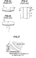
- the hearth roll shown in Fig. la has tapered ends.
- the hearth roll shown in Fig. lb has a crowning outer circumferential surface. These hearth rolls serve to a certain extent to prevent metal strip from meandering.
- tapered angles 8 as shown in Fig. la or crowning amounts or curvatures 1/p shown in Fig. lb are too large or tensile forces in longitudinal directions in the metal strips increase, then compressive stresses are caused by uneven tensile forces in the metal strips, which in turn give rise to buckling of the metal strips.
- the metal strips are likely to cause bucklings 3 at locations corresponding to taper starting lines of the rolls. Such bucklings spoil the appearance of the metal strip so as to lose their worth as products. In some extreme cases, moreover, the metal strips are broken off due to the bucklings resulting in a great trouble.
- Fig. 3 is a graph symbolically illustrating this fact.
- a lower left shaded portion is a meandering zone and an upper right shaded portion is a buckling zone. Between these zones there is a narrow zone in which any meandering and buckling of metal strips do not occur. It is clearly evident that there are limited proper values of the tapered angles 6 and curvatures 1/p of the hearth rolls.
- metal strips to be treated in the continuous annealing furnaces are in wide ranges of dimension (thickness and width) and material (strength at high temperature and heat-treatment condition).
- the proper zone shown in Fig. 3 varies with these factors of metal strips.
- the shape of the hearth rolls was determined when the plant was constructed. Accordingly, the adaptability to the variation in metal strips is insufficient to avoid the buckling and meandering of the metal strips.
- auxiliary small diameter rolls in order to prevent the buckling of metal strips due to the hearth rolls of annealing furances (Japanese Patent Application No. 188,257/82).
- the method using the auxiliary small diameter rolls exhibits significant effect for preventing the buckling but does not exhibit any improved effect for controlling the meandering in comparison with the prior art.
- the inventors have carried out various experiments with various shapes of hearth rolls and operating conditions in order to prevent the buckling and to control the meandering. As the result, they have found that the buckling of metal strips can be completely avoided in the event that taper angles and crowning amounts of hearth rolls are zero or very small, and the position of the metal strips in traverse directions of the hearth rolls can be very easily controlled by changing parallelism between axes of the hearth rolls and separate cylindrical rolls arranged adjacent to the hearth rolls. They have completed this invention based on this discovery.
- a continuous annealing apparatus for metal strips comprises cylindrical rolls each arranged at a location immediately before the metal strip passes about a hearth roll in a high temperature heat-treatment region of the apparatus, an axis of said cylindrical roll being finely tiltable relative to an axis of said hearth roll.
- the cylindrical roll is supported at its ends by bearings, one of which is made shiftable transversely to an axis of the cylindrical roll by means of hydraulic means.
- the metal strip 2 moves in a direction shown by arrows in Fig. 4 in a manner that after the metal strip 2 has contacted each the finely tiltable cylindrical roll 7, it is trained about the hearth roll 6 having no taper portions or crowning eliminating the risk of buckling, and then passes about the next hearth roll 1.
- Fig. 5 illustrates a finely tiltable cylindrical roll 7 and a hearth roll 6 in a plan view, wherein a metal strip 2 moves in a direction shown by an arrow 2a.
- the finely tiltable cylindrical roll 7 is supported at its roll ends 8 by means of bearings 9, one of the bearings 9 being shiftable in horizontal directions traverse to an axis of. the roll 7, for example, by means of a hydraulic cylinder 10.
- the axis of the small diameter cylindrical roll 7 can freely make a tilting angle ⁇ relative to an axis 11 of the hearth roll 6 within a range corresponding to a stroke of the hydraulic cylinder.
- the inventors have investigated in experiment how much change in traverse position of metal strips 2 is caused depending upon the variation in tilting angle of the cylindrical roll 7. The result of the investigation will be explained hereinafter.
- Fig. 6 shows relations between rotated numbers of hearth rolls and shifted distances Mx of strips 2 in traverse directions depending upon tilting angles ⁇ of tiltable cylindrical rolls.
- Fig. 7 is a plan view for explaining Fig. 6, wherein Mx is a shifted distance of a center line C 2 of a metal strip 2 (shown by oblique stripes) from a center line C 1 of a hearth roll 6.
- Mx is a shifted distance of a center line C 2 of a metal strip 2 (shown by oblique stripes) from a center line C 1 of a hearth roll 6.
- the shifted distance Mx of the metal strip 2 was measured with rotated numbers of the hearth roll 6, while the tilting angle ⁇ of the finely tiltable cylindrical roll 7 in a horizontal plane relative to an axis of the hearth roll 6 was changed in various angles.
- the rotated numbers of the hearth roll and the shifted distances Mx are in a linear relation or proportional to each other.
- the metal strip 2 is shifted in its width direction by 75 mm per 100 rotations of the hearth roll.
- the larger the tilting angle ⁇ the higher is the shifting speed (Mx/rotated number of hearth roll) of the metal strip as shown in Fig. 6.
- the tiltable cylindrical roll 7 tilted more than 0.5 degree is likely to cause shearing forces in the metal strip, which in turn cause oblique buckling 13 as shown in Fig. 8. It is therefore preferable to control the tilting angle ⁇ within a range less than 0.4 degree.
- a finely tiltable cylindrical roll 7 capable of changing its tilting angle was provided by a device as shown in Fig. 5 in front of each of respective two hearth rolls 6 on outlet side of a heating zone 4 and on inlet side of a soaking zone 5, or immediately before each a turn of a metal strip about each the hearth roll 6 as shown in Fig. 4.
- the hearth rolls and tiltable cylindrical rolls did not have tapered portions and crowning and had radii of 300 mm and 150 mm, respectively.
- Metal strips used in the experiment were metal strips, which were intended to be tin-plated to produce tin plates, having a thickness 0.3 mm and a width of 900 mm, and very low-carbon steel strips having a thickness of 0.7 mm and a width of 1,320 mm. These strips were passed through the apparatus at a speed 200 m/min to be heat-treated. A temperature in the soaking zone was 810°C.
- Table 1 shows the meandering and buckling of the above strips in comparison of the apparatus according to the present invention and the prior art apparatus having tapered hearth rolls.
- marks of , A and x denote "good", "a little bad” and "bad", respectively.
Abstract
Description
- This invention relates to a continuous annealing apparatus having finely tiltable cylindrical rolls for guiding beltlike metals or metal strips adjacent to hearth rolls in a high temperature heat-treatment region of a vertical continuous annealing furnace for use in heat-treatment of the metal strips.
- A continuous annealing furnace generally includes in series from an upstream to a downstream side a heating, a soaking and a cooling zone through which metal strips progressively pass so as to be properly heat-treated in accordance with various purposes.
- In operation with such an apparatus, metal strips are often meandering or staggering in traverse directions and are buckling in the strips.
- In order to avoid the meandering of the metal strips, it has been proposed to use hearth rolls having larger diameters at their midportions in the same manner as in belt pulleys. Figs. la and lb illustrate examples of such hearth rolls. The hearth roll shown in Fig. la has tapered ends. The hearth roll shown in Fig. lb has a crowning outer circumferential surface. These hearth rolls serve to a certain extent to prevent metal strip from meandering. When tapered
angles 8 as shown in Fig. la or crowning amounts or curvatures 1/p shown in Fig. lb are too large or tensile forces in longitudinal directions in the metal strips increase, then compressive stresses are caused by uneven tensile forces in the metal strips, which in turn give rise to buckling of the metal strips. - When the tapered hearth rolls la are used, the metal strips are likely to cause
bucklings 3 at locations corresponding to taper starting lines of the rolls. Such bucklings spoil the appearance of the metal strip so as to lose their worth as products. In some extreme cases, moreover, the metal strips are broken off due to the bucklings resulting in a great trouble. - On the other hand, when the tapered angles or crowning amounts are reduced in order to avoid the bucklings, the performance of the hearth rolls preventing the meandering of the metal strips is lost to make impossible the proper transferring of the metal strips. In extreme cases, the metal strips are detached from the rolls and edges of the strips scrape the furnace walls to cause large troubles.
- Fig. 3 is a graph symbolically illustrating this fact. A lower left shaded portion is a meandering zone and an upper right shaded portion is a buckling zone. Between these zones there is a narrow zone in which any meandering and buckling of metal strips do not occur. It is clearly evident that there are limited proper values of the
tapered angles 6 and curvatures 1/p of the hearth rolls. In general, metal strips to be treated in the continuous annealing furnaces are in wide ranges of dimension (thickness and width) and material (strength at high temperature and heat-treatment condition). The proper zone shown in Fig. 3 varies with these factors of metal strips. However, the shape of the hearth rolls was determined when the plant was constructed. Accordingly, the adaptability to the variation in metal strips is insufficient to avoid the buckling and meandering of the metal strips. - The inventors have proposed to use auxiliary small diameter rolls in order to prevent the buckling of metal strips due to the hearth rolls of annealing furances (Japanese Patent Application No. 188,257/82). The method using the auxiliary small diameter rolls exhibits significant effect for preventing the buckling but does not exhibit any improved effect for controlling the meandering in comparison with the prior art.
- The inventors have carried out various experiments with various shapes of hearth rolls and operating conditions in order to prevent the buckling and to control the meandering. As the result, they have found that the buckling of metal strips can be completely avoided in the event that taper angles and crowning amounts of hearth rolls are zero or very small, and the position of the metal strips in traverse directions of the hearth rolls can be very easily controlled by changing parallelism between axes of the hearth rolls and separate cylindrical rolls arranged adjacent to the hearth rolls. They have completed this invention based on this discovery.
- It is therefore an object of the invention to provide a continuous annealing apparatus which eliminates the above disadvantages of the prior art.
- It is another object of the invention to provide a continuous annealing apparatus performing continuous annealing of metal strips under wide conditions with the aid of means capable of simultaneously fulfilling the imcompatible performances of prevention of meandering and buckling in the metal strips in general caused by hearth rolls.
- To this end, a continuous annealing apparatus for metal strips according to the invention comprises cylindrical rolls each arranged at a location immediately before the metal strip passes about a hearth roll in a high temperature heat-treatment region of the apparatus, an axis of said cylindrical roll being finely tiltable relative to an axis of said hearth roll.
- In a preferred embodiment of the invention, the cylindrical roll is supported at its ends by bearings, one of which is made shiftable transversely to an axis of the cylindrical roll by means of hydraulic means.
- The invention will be more fully understood by referring to the following detailed specification and claims taken in connection with the appended drawings.
- Fig. la is a front elevation illustrating an external appearance of a hearth roll having tapered ends of the prior art;
- Fig. lb is a tront elevation illustrating an external appearance of a hearth roll having crowning of the prior art;
- Fig. 2 is a front elevation illustrating bucklings occuring in a metal strip at shoulders of a hearth roll of the prior art;
- Fig. 3 is a graph symbolically illustrating relations between tapered angles or curvatures of hearth rolls and buckling and meandering of metal strips;
- Fig. 4 is a schematic sectional view of a furnace including a vertical continuous annealing apparatus of one embodiment of the invention;
- Fig. 5 is a schematic plan view of one embodiment of a tilting mechanism for a finely tiltable cylindrical roll according to the invention;
- Fig. 6 is a graph illustrating relations between shifted distances of metal strips and tilting angles of the finely tiltable cylindrical rolls according to the invention;
- Fig. 7 is a schematic plan view illustrating the shift of a metal strip on a hearth roll caused by a tiltable cylindrical roll according to the invention; and
- Fig. 8 is a front elevation of a metal strip in which buckling is caused by shearing force.
- Fig. 4 illustrates a positional relation between rolls and a
metal strip 2 in aheating zone 4 and a part of asoaking zone 5 in a high temperature heat-treatment region of a vertical continuous annealing furnace. In the annealing furance shown in Fig. 4, the two upper rolls in the heating zone near to thesoaking zone 5 and the two upper rolls in the soaking zone near to the heating zone arehearth rolls 6 which do not have tapered portions or crowning. Immediately before each thehearth roll 6 in a path of the metal strip is a small diametercylindrical roll 7 whose axis is finely tiltable from a parallel position relative to an axis of thehearth roll 6 by the use of means for sliding or moving at least one bearing on one end of thecylindrical roll 7. - The
metal strip 2 moves in a direction shown by arrows in Fig. 4 in a manner that after themetal strip 2 has contacted each the finely tiltablecylindrical roll 7, it is trained about thehearth roll 6 having no taper portions or crowning eliminating the risk of buckling, and then passes about the next hearth roll 1. - Fig. 5 illustrates a finely tiltable
cylindrical roll 7 and ahearth roll 6 in a plan view, wherein ametal strip 2 moves in a direction shown by anarrow 2a. The finely tiltablecylindrical roll 7 is supported at itsroll ends 8 by means of bearings 9, one of the bearings 9 being shiftable in horizontal directions traverse to an axis of. theroll 7, for example, by means of ahydraulic cylinder 10. The axis of the small diametercylindrical roll 7 can freely make a tilting angle φ relative to an axis 11 of thehearth roll 6 within a range corresponding to a stroke of the hydraulic cylinder. - The inventors have investigated in experiment how much change in traverse position of
metal strips 2 is caused depending upon the variation in tilting angle of thecylindrical roll 7. The result of the investigation will be explained hereinafter. - Fig. 6 shows relations between rotated numbers of hearth rolls and shifted distances Mx of
strips 2 in traverse directions depending upon tilting angles ϕ of tiltable cylindrical rolls. Fig. 7 is a plan view for explaining Fig. 6, wherein Mx is a shifted distance of a center line C2 of a metal strip 2 (shown by oblique stripes) from a center line C1 of ahearth roll 6. At first, themetal strip 2 extended about thehearth roll 6 in a manner the center lines C1 and C2 were coincident with each other or Mx=0, and then themetal strip 2 was driven by thehearth roll 6. The shifted distance Mx of themetal strip 2 was measured with rotated numbers of thehearth roll 6, while the tilting angle ϕ of the finely tiltablecylindrical roll 7 in a horizontal plane relative to an axis of thehearth roll 6 was changed in various angles. As can be seen from Fig. 6, the rotated numbers of the hearth roll and the shifted distances Mx are in a linear relation or proportional to each other. In the event of the tilting angle ϕ of 0.2 degree, themetal strip 2 is shifted in its width direction by 75 mm per 100 rotations of the hearth roll. The larger the tilting angle ϕ, the higher is the shifting speed (Mx/rotated number of hearth roll) of the metal strip as shown in Fig. 6. However, the tiltablecylindrical roll 7 tilted more than 0.5 degree is likely to cause shearing forces in the metal strip, which in turn cause oblique buckling 13 as shown in Fig. 8. It is therefore preferable to control the tilting angle ϕ within a range less than 0.4 degree. - The effect of the invention was ascertained in an actual apparatus, the result of which will be explained hereinafter. A finely tiltable
cylindrical roll 7 capable of changing its tilting angle was provided by a device as shown in Fig. 5 in front of each of respective two hearth rolls 6 on outlet side of aheating zone 4 and on inlet side of a soakingzone 5, or immediately before each a turn of a metal strip about each thehearth roll 6 as shown in Fig. 4. The hearth rolls and tiltable cylindrical rolls did not have tapered portions and crowning and had radii of 300 mm and 150 mm, respectively. - Metal strips used in the experiment were metal strips, which were intended to be tin-plated to produce tin plates, having a thickness 0.3 mm and a width of 900 mm, and very low-carbon steel strips having a thickness of 0.7 mm and a width of 1,320 mm. These strips were passed through the apparatus at a speed 200 m/min to be heat-treated. A temperature in the soaking zone was 810°C.
-
Television cameras 12 for industrial use were arranged at locations shown in Fig. 4 to monitor the meandering of the strips. The tilting angle φ of each the tiltable cylindrical roll was changed by 0.15 degree in directions compensating for shifted distances in response to every 50 mm shift in the traverse direction of the strip detected by thetelevision camera 12. Table 1 shows the meandering and buckling of the above strips in comparison of the apparatus according to the present invention and the prior art apparatus having tapered hearth rolls. In the Table 1, marks of , A and x denote "good", "a little bad" and "bad", respectively.
- In case of the metal strips for tin plates, they greatly meandered in the prior art apparatus to cause shearing forces in the strips resulting in oblique buckling as shown at 13 in Fig. 8. In contrast herewith, with the apparatus according to the invention the meandering and buckling were completely prevented by controlling the tilting angles ϕ of the finely tiltable cylindrical rolls within 0.15 degree.
- In case of the very low-carbon steel strips, with the prior art apparatus they did not meander but exhibited buckling 3 in the strips at locations corresponding to shoulders of the hearth rolls as shown in Fig. 2. With the apparatus according to the invention, such a buckling was not caused because the hearth rolls are completely cylindrical. With the apparatus according to the invention, moreover, without the control by the finely tiltable
cylindrical rolls 7, the meandering of the strips was larger than that of the prior art, but such a meandering was completely avoided by controlling the tilting angle ϕ within 0.15 degree.. - While the invention has been particularly shown and described with reference to preferred embodiments thereof, it will be understood by those skilled in the art that the foregoing and other changes in form and details can be made therein without departing from the spirit and scope of the invention.
Claims (5)
Applications Claiming Priority (2)
| Application Number | Priority Date | Filing Date | Title |
|---|---|---|---|
| JP58144314A JPS6036626A (en) | 1983-08-06 | 1983-08-06 | Continuous annealing device |
| JP144314/83 | 1983-08-06 |
Publications (2)
| Publication Number | Publication Date |
|---|---|
| EP0138298A1 true EP0138298A1 (en) | 1985-04-24 |
| EP0138298B1 EP0138298B1 (en) | 1987-04-15 |
Family
ID=15359203
Family Applications (1)
| Application Number | Title | Priority Date | Filing Date |
|---|---|---|---|
| EP84304392A Expired EP0138298B1 (en) | 1983-08-06 | 1984-06-28 | Continuous annealing apparatus |
Country Status (5)
| Country | Link |
|---|---|
| US (1) | US4575053A (en) |
| EP (1) | EP0138298B1 (en) |
| JP (1) | JPS6036626A (en) |
| CA (1) | CA1214037A (en) |
| DE (1) | DE3463161D1 (en) |
Cited By (1)
| Publication number | Priority date | Publication date | Assignee | Title |
|---|---|---|---|---|
| US9104016B2 (en) | 2004-10-08 | 2015-08-11 | Carl Zeiss Smt Gmbh | Optical projection system |
Families Citing this family (3)
| Publication number | Priority date | Publication date | Assignee | Title |
|---|---|---|---|---|
| US4759807A (en) * | 1986-12-29 | 1988-07-26 | Rasmet Ky | Method for producing non-aging hot-dip galvanized steel strip |
| JPH01172526A (en) * | 1987-12-26 | 1989-07-07 | Nkk Corp | Method for preventing snaking in continuous strip treatment line |
| KR100953073B1 (en) * | 2002-11-26 | 2010-04-13 | 주식회사 포스코 | Apparatus for preventing heat deformation of strip in continuous heat treatment furnace |
Citations (8)
| Publication number | Priority date | Publication date | Assignee | Title |
|---|---|---|---|---|
| US2451394A (en) * | 1945-07-12 | 1948-10-12 | Chain Belt Co | Self-aligning conveyer roll mounting |
| DE1860060U (en) * | 1961-12-30 | 1962-10-11 | Siemens Ag | STRAIGHT DEVICE FOR A CONVEYOR BELT. |
| US3175813A (en) * | 1962-12-31 | 1965-03-30 | Nat Steel Corp | Edge position control of strip material in furnaces |
| US3188063A (en) * | 1963-07-18 | 1965-06-08 | Nat Steel Corp | Method and apparatus for controlling the position of strip material in furnaces |
| GB1059559A (en) * | 1963-12-23 | 1967-02-22 | Ruthner Othmar | Controlling the transverse register of a web |
| US3610494A (en) * | 1969-09-08 | 1971-10-05 | Carl H Minton | Strip steering roll assembly |
| EP0037752A1 (en) * | 1980-03-26 | 1981-10-14 | UNION SIDERURGIQUE DU NORD ET DE L'EST DE LA FRANCE par abréviation "USINOR" | Device for guiding webs and its applications |
| EP0108328A1 (en) * | 1982-10-28 | 1984-05-16 | Kawasaki Steel Corporation | Continuous annealing apparatus |
Family Cites Families (5)
| Publication number | Priority date | Publication date | Assignee | Title |
|---|---|---|---|---|
| US2666003A (en) * | 1949-02-18 | 1954-01-12 | Bethlehem Steel Corp | Treating strip |
| DE1202300B (en) * | 1963-12-30 | 1965-10-07 | Mannesmann Ag | Pull-through furnace for continuous tension relief of strip-shaped rolled products |
| JPS5943979B2 (en) * | 1979-10-31 | 1984-10-25 | 川崎製鉄株式会社 | Furnace tension control method |
| DE3013840A1 (en) * | 1980-04-10 | 1981-10-15 | Ernst Roederstein Spezialfabrik für Kondensatoren GmbH, 8300 Landshut | Foil band winding installation - has reversing roller placed in turnable position in front of winding roller made as wobble roller |
| US4385945A (en) * | 1981-11-19 | 1983-05-31 | Armco Inc. | Lift-off means and method for use with a horizontal continuous hearth roll furnace for the treatment of metallic strip |
-
1983
- 1983-08-06 JP JP58144314A patent/JPS6036626A/en active Granted
-
1984
- 1984-06-25 US US06/623,950 patent/US4575053A/en not_active Expired - Lifetime
- 1984-06-28 DE DE8484304392T patent/DE3463161D1/en not_active Expired
- 1984-06-28 EP EP84304392A patent/EP0138298B1/en not_active Expired
- 1984-06-29 CA CA000457861A patent/CA1214037A/en not_active Expired
Patent Citations (8)
| Publication number | Priority date | Publication date | Assignee | Title |
|---|---|---|---|---|
| US2451394A (en) * | 1945-07-12 | 1948-10-12 | Chain Belt Co | Self-aligning conveyer roll mounting |
| DE1860060U (en) * | 1961-12-30 | 1962-10-11 | Siemens Ag | STRAIGHT DEVICE FOR A CONVEYOR BELT. |
| US3175813A (en) * | 1962-12-31 | 1965-03-30 | Nat Steel Corp | Edge position control of strip material in furnaces |
| US3188063A (en) * | 1963-07-18 | 1965-06-08 | Nat Steel Corp | Method and apparatus for controlling the position of strip material in furnaces |
| GB1059559A (en) * | 1963-12-23 | 1967-02-22 | Ruthner Othmar | Controlling the transverse register of a web |
| US3610494A (en) * | 1969-09-08 | 1971-10-05 | Carl H Minton | Strip steering roll assembly |
| EP0037752A1 (en) * | 1980-03-26 | 1981-10-14 | UNION SIDERURGIQUE DU NORD ET DE L'EST DE LA FRANCE par abréviation "USINOR" | Device for guiding webs and its applications |
| EP0108328A1 (en) * | 1982-10-28 | 1984-05-16 | Kawasaki Steel Corporation | Continuous annealing apparatus |
Cited By (3)
| Publication number | Priority date | Publication date | Assignee | Title |
|---|---|---|---|---|
| US9104016B2 (en) | 2004-10-08 | 2015-08-11 | Carl Zeiss Smt Gmbh | Optical projection system |
| US9557653B2 (en) | 2004-10-08 | 2017-01-31 | Carl Zeiss Smt Gmbh | Optical projection system |
| US9891535B2 (en) | 2004-10-08 | 2018-02-13 | Carl Zeiss Smt Gmbh | Optical projection system |
Also Published As
| Publication number | Publication date |
|---|---|
| CA1214037A (en) | 1986-11-18 |
| JPS6261650B2 (en) | 1987-12-22 |
| US4575053A (en) | 1986-03-11 |
| EP0138298B1 (en) | 1987-04-15 |
| DE3463161D1 (en) | 1987-05-21 |
| JPS6036626A (en) | 1985-02-25 |
Similar Documents
| Publication | Publication Date | Title |
|---|---|---|
| US9255738B2 (en) | Method and apparatus for heating a sheet-like product | |
| US4575053A (en) | Continuous annealing apparatus | |
| CA1280190C (en) | Method and system for controlling tension to be exerted on metal strip in continuous annealing furnace | |
| KR100323469B1 (en) | Band rolling method and device | |
| US4571274A (en) | Method for continuous annealing of a metal strip | |
| KR900001092B1 (en) | Apparatus for colling strip of metals | |
| KR102289157B1 (en) | Steel plate transfer device | |
| US6238209B1 (en) | Hearth rolls for heating furnace and soaking furnace of vertical heat treating furnace and vertical heat treating furnace including hearth rolls | |
| EP0108328B1 (en) | Continuous annealing apparatus | |
| CA1245136A (en) | Continuous annealing method and apparatus for cold rolled steel strips | |
| JPH02179308A (en) | Method for controlling sheet crown during hot rolling | |
| EP0202023A2 (en) | Support device for moving metal strip | |
| EP1158059B1 (en) | Use of a hearth roll in a method for heat treating a variety of metal strips in a vertical heat treating furnace including hearth rolls | |
| KR100511117B1 (en) | Hearth rolls for heating furnace and soaking furnace of vertical heat treating furnace and vertical heat treating furnace including hearth rolls | |
| JPS6369924A (en) | Method for preventing meandering of metallic strip | |
| CA2062527A1 (en) | Heating furnace | |
| DE4203395C2 (en) | Method for guiding thin slabs, sheets and steel strips to be heated in high-temperature roller hearth furnaces and high-temperature roller hearth furnace for carrying out the method | |
| JPS6144924B2 (en) | ||
| JP3465742B2 (en) | Hearth roll for vertical heat treatment furnace and vertical heat treatment furnace using the hearth roll | |
| US6206083B1 (en) | Strip casting device | |
| CA2257540C (en) | Strip casting device | |
| JPS6237697B2 (en) | ||
| JPS6343450B2 (en) | ||
| JP5724683B2 (en) | Method for preventing meandering and drawing of steel strip in horizontal heat treatment furnace | |
| JPS61264138A (en) | Continuous annealing method for steel strip |
Legal Events
| Date | Code | Title | Description |
|---|---|---|---|
| PUAI | Public reference made under article 153(3) epc to a published international application that has entered the european phase |
Free format text: ORIGINAL CODE: 0009012 |
|
| AK | Designated contracting states |
Designated state(s): DE FR GB |
|
| 17P | Request for examination filed |
Effective date: 19850501 |
|
| GRAA | (expected) grant |
Free format text: ORIGINAL CODE: 0009210 |
|
| AK | Designated contracting states |
Kind code of ref document: B1 Designated state(s): DE FR GB |
|
| ET | Fr: translation filed | ||
| REF | Corresponds to: |
Ref document number: 3463161 Country of ref document: DE Date of ref document: 19870521 |
|
| PLBE | No opposition filed within time limit |
Free format text: ORIGINAL CODE: 0009261 |
|
| STAA | Information on the status of an ep patent application or granted ep patent |
Free format text: STATUS: NO OPPOSITION FILED WITHIN TIME LIMIT |
|
| 26N | No opposition filed | ||
| PGFP | Annual fee paid to national office [announced via postgrant information from national office to epo] |
Ref country code: GB Payment date: 19980619 Year of fee payment: 15 |
|
| PG25 | Lapsed in a contracting state [announced via postgrant information from national office to epo] |
Ref country code: GB Free format text: LAPSE BECAUSE OF NON-PAYMENT OF DUE FEES Effective date: 19990628 |
|
| GBPC | Gb: european patent ceased through non-payment of renewal fee |
Effective date: 19990628 |
|
| PGFP | Annual fee paid to national office [announced via postgrant information from national office to epo] |
Ref country code: FR Payment date: 20030610 Year of fee payment: 20 |
|
| PGFP | Annual fee paid to national office [announced via postgrant information from national office to epo] |
Ref country code: DE Payment date: 20030710 Year of fee payment: 20 |