EP0138170A2 - Air-to-fuel ratio detector for engines - Google Patents
Air-to-fuel ratio detector for engines Download PDFInfo
- Publication number
- EP0138170A2 EP0138170A2 EP84111936A EP84111936A EP0138170A2 EP 0138170 A2 EP0138170 A2 EP 0138170A2 EP 84111936 A EP84111936 A EP 84111936A EP 84111936 A EP84111936 A EP 84111936A EP 0138170 A2 EP0138170 A2 EP 0138170A2
- Authority
- EP
- European Patent Office
- Prior art keywords
- oxygen
- air
- fuel ratio
- pump
- pump current
- Prior art date
- Legal status (The legal status is an assumption and is not a legal conclusion. Google has not performed a legal analysis and makes no representation as to the accuracy of the status listed.)
- Granted
Links
Images
Classifications
-
- F—MECHANICAL ENGINEERING; LIGHTING; HEATING; WEAPONS; BLASTING
- F02—COMBUSTION ENGINES; HOT-GAS OR COMBUSTION-PRODUCT ENGINE PLANTS
- F02D—CONTROLLING COMBUSTION ENGINES
- F02D41/00—Electrical control of supply of combustible mixture or its constituents
- F02D41/02—Circuit arrangements for generating control signals
- F02D41/14—Introducing closed-loop corrections
-
- G—PHYSICS
- G01—MEASURING; TESTING
- G01N—INVESTIGATING OR ANALYSING MATERIALS BY DETERMINING THEIR CHEMICAL OR PHYSICAL PROPERTIES
- G01N27/00—Investigating or analysing materials by the use of electric, electrochemical, or magnetic means
- G01N27/26—Investigating or analysing materials by the use of electric, electrochemical, or magnetic means by investigating electrochemical variables; by using electrolysis or electrophoresis
- G01N27/416—Systems
- G01N27/417—Systems using cells, i.e. more than one cell and probes with solid electrolytes
-
- F—MECHANICAL ENGINEERING; LIGHTING; HEATING; WEAPONS; BLASTING
- F02—COMBUSTION ENGINES; HOT-GAS OR COMBUSTION-PRODUCT ENGINE PLANTS
- F02D—CONTROLLING COMBUSTION ENGINES
- F02D41/00—Electrical control of supply of combustible mixture or its constituents
- F02D41/02—Circuit arrangements for generating control signals
- F02D41/14—Introducing closed-loop corrections
- F02D41/1438—Introducing closed-loop corrections using means for determining characteristics of the combustion gases; Sensors therefor
- F02D41/1473—Introducing closed-loop corrections using means for determining characteristics of the combustion gases; Sensors therefor characterised by the regulation method
- F02D41/1475—Regulating the air fuel ratio at a value other than stoichiometry
- F02D41/1476—Biasing of the sensor
-
- G—PHYSICS
- G01—MEASURING; TESTING
- G01N—INVESTIGATING OR ANALYSING MATERIALS BY DETERMINING THEIR CHEMICAL OR PHYSICAL PROPERTIES
- G01N27/00—Investigating or analysing materials by the use of electric, electrochemical, or magnetic means
-
- F—MECHANICAL ENGINEERING; LIGHTING; HEATING; WEAPONS; BLASTING
- F02—COMBUSTION ENGINES; HOT-GAS OR COMBUSTION-PRODUCT ENGINE PLANTS
- F02B—INTERNAL-COMBUSTION PISTON ENGINES; COMBUSTION ENGINES IN GENERAL
- F02B1/00—Engines characterised by fuel-air mixture compression
- F02B1/02—Engines characterised by fuel-air mixture compression with positive ignition
- F02B1/04—Engines characterised by fuel-air mixture compression with positive ignition with fuel-air mixture admission into cylinder
-
- F—MECHANICAL ENGINEERING; LIGHTING; HEATING; WEAPONS; BLASTING
- F02—COMBUSTION ENGINES; HOT-GAS OR COMBUSTION-PRODUCT ENGINE PLANTS
- F02D—CONTROLLING COMBUSTION ENGINES
- F02D41/00—Electrical control of supply of combustible mixture or its constituents
- F02D41/02—Circuit arrangements for generating control signals
- F02D41/14—Introducing closed-loop corrections
- F02D41/1438—Introducing closed-loop corrections using means for determining characteristics of the combustion gases; Sensors therefor
- F02D41/1444—Introducing closed-loop corrections using means for determining characteristics of the combustion gases; Sensors therefor characterised by the characteristics of the combustion gases
- F02D41/1454—Introducing closed-loop corrections using means for determining characteristics of the combustion gases; Sensors therefor characterised by the characteristics of the combustion gases the characteristics being an oxygen content or concentration or the air-fuel ratio
- F02D41/1456—Introducing closed-loop corrections using means for determining characteristics of the combustion gases; Sensors therefor characterised by the characteristics of the combustion gases the characteristics being an oxygen content or concentration or the air-fuel ratio with sensor output signal being linear or quasi-linear with the concentration of oxygen
Definitions
- the present invention relates to an air-to-fuel ratio detector (designated as “A/F ratio detector” hereinafter) for detecting the air-to-fuel ratio (designated as “A/F ratio” hereinafter) of the combustible air/fuel mixture supplied to an internal-combustion engine for an automobile or the like and more particularly to an oxygen pump type A/F ratio detector employing an ion-conductive solid electrolyte.
- an engine for example, an automotive engine
- such an oxygen sensor has a disadvantage that the output of the oxygen sensor varies greatly when the A/F ratio of the combustible mixture is around the stoichiometric A/F ratio, whereas the output of the oxygen sensor varies scarecely when the operating R/F ratio is an A/F ratio other than the stoichiometric A/F ratio, and hence the output of the oxygen sensor can not be used for controlling the operation of the engine when the engine is operated at an A/F ratio other than the stoichiometric A/F ratio.
- the principle of the present invention is based on a fact that, in an A/F ratio sensor consisting of an oxygen pump and an oxygen sensor, the A/F ratio detecting range is shifted from a range over the stoichiometric A/F ratio to a range below the stoichiometric A/F ratio and vice versa when the direction of the electric current supplied to the oxygen pump is changed.
- An A/F ratio detector comprises: an A/F ratio sensor having an oxygen pump and an oxygen sensor disposed opposite to each other with a minute gap therebetween in the exhaust gas passage of an engine and each being formed by attaching electrodes to the opposite sides of a flat plate of a solid electrolyte respectively; current supply means to supply a pump current to the oxygen pump; electromotive force detecting means to detect the magnitude of an electromotive force generated proportionally to the difference between the oxygen partial pressure within the gap and the oxygen partial pressure outside the gap by the oxygen sensor supplied with a predetermined pump current; pump current control means to control the pump current to be supplied to the oxygen pump so that the electromotive force detected by the electromotive force detecting means is maintained at a fixed level; means to give an A/F ratio detection output which is proportional to the pump current; and changeover means to change over the direction of the pump current supplied to the oxygen pump and the polarity of the output signal of the oxygen sensor simultaneously.
- the present invention provides also an A/F ratio control unit capable of controlling the A/F ratio accurately over a wide range of A/F ratio through the feedback control of the A/F ratio of the combustible mixture supplied to the engine, on the basis of the A/F ratio detection output by actuating the changeover means when the operating A/F ratio is changed from a lean region to a rich region with respect to the stoichiometric A/F ratio.
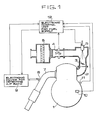
- Fig. 1 shows a preferred embodiment of the present invention.
- indicated at 1 is an engine, at 2 a suction pipe of the engine 1, at 3 a throttle valve, at 4 a suction air quantity detecting unit for detecting the quantity of air sucked by the engine 1, at 5 a fuel feed valve disposed upstream with respect to the throttle valve 3, at 6 an air cleaner disposed upstream with respect to the suction air quantity detecting unit 4, at 7 the exhaust pipe of the engine 1, at 8 an A/F ratio sensor attached to the exhaust pipe 7, at 9 an electronic device for detecting A/F ratio, at 10 a revolving rate detector for detecting the revolving rate of the engine 1, at 11 a temperature detector for detecting the temperature of the engine 1 and at 12 an electronic control unit which receives the respective output signals of the temperature detector 11, the suction air quantity detecting unit 4, the electronic device 9 and the revolving rate detector 10 as input information and controls fuel feed rate by driving the
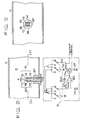
- the A/F ratio sensor 8 comprises a solid electrolyte oxygen pump 16 formed of a flat ion-conductive solid electrolyte plate 13, such as a flat plate of a stabilized zirconia of 0.5 mm thick and provided on the opposite sides thereof with Pt electrodes 14 and 15, a solid electrolyte oxygen sensor 20 formed similarly to the oxygen pump 16 of the flat ion-conductive solid electrolyte plate 17 provided on the opposite sides thereof with Pt electrodes 18 and 19 respectively and a support 21 for supporting the oxygen pump 16 and the oxygen sensor 20 opposite to each other with a minute gap d having a width of about 0.1 mm therebetween.
- a solid electrolyte oxygen pump 16 formed of a flat ion-conductive solid electrolyte plate 13, such as a flat plate of a stabilized zirconia of 0.5 mm thick and provided on the opposite sides thereof with Pt electrodes 14 and 15, a solid electrolyte oxygen sensor 20 formed similarly to the oxygen pump 16 of the flat ion-conductive solid electrolyte plate
- the electronic device 9 for detecting A/F ratio includes an operational amplifier 30 has an inversion input terminal which receives an electromotive force e generated between the electrodes 18 and 19 of the oxygen sensor 20 through a resistance Rl and a non-inversion input terminal to which a reference voltage is applied by a reference voltage source V R .
- a capacitor Cl is connected between the output terminal and the inversion input terminal of the operational amplifier 30.
- the output terminal of the operational amplifier 30 is connected to the base of a transistor TR and the collector of the transistor TR is connected to a DC power source 31.
- An output signal given through the emitter of the transistor TR is transmitted through a resistance R 0 as a pump current to the oxygen pump 16.
- the changeover switch SW consisting of mutually interlocked four switching elements is provided to change over the respective polarities of the electromotive force e which is supplied to the inversion input terminal of the operational amplifier 30 and the pump current Ip which is supplied to the oxygen pump 16.
- the electromotive force e generated by the oxygen sensor 20 is compared with the voltage of the reference voltage source V R by the operational amplifier 30.
- the operational amplifier 30 gives a signal proportional to the difference between the electromotive force e and the voltage of the reference voltage source V R to the base of the transistor TR.
- the pump current Ip that flows from the DC power source 31 through the transistor TR and the resistance R to the oxygen pump 16 is controlled according to the electromotive force e generated by the oxygen sensor 20.
- a voltage generated at the opposite terminals of the resistance R O proportionally to the pump current Ip is taken out as an output signal.
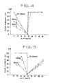
- Figs. 4 and 5 are graphs showing the characteristics of the A/F ratio sensor according to the present invention shown in Fig. 2, obtained through the test operation of a gasoline engine of 2000 cc nominal displacement equipped with the A/F ratio sensor 8 of the present invention for a domestic automobile.
- the upper limit of the pump current Ip was limited to 120 mA by the DC power source B, because an excessive pump current Ip damages the oxygen pump 16.
- the characteristics diagram of Fig. 4 shows the relation between the pump current Ip and the operating A/F ratio of the combustible mixture supplied to the engine for the variation of the electromotive force when the pump current Ip flows in the oxygen pump 16 from the electrode 15 disposed nearby the minute gap as a positive electrode to the electrode 14 as a negative electrode.
- Fig. 5 shows the results of the test operation in which the changeover switch SW was arranged so that the pump current Ip would flow in the oxygen pump 16 from the electrode 14 to the electrode 15. In this case, on the contrary to the case of Fig.
- the oxygen partial pressure within the minute gap becomes lower than the oxygen partial pressure outside the minute gap in the exhaust gas, and hence an electromotive force e is generated in the oxygen sensor 20 with the electrode 18 as a positive electrode. Accordingly, the changeover switch SW changes over the circuit so that the electrode 18 of positive polarity is connected to the inversion input terminal of the operational amplifier 30.
- the rate of variation of the pump current Ip with the variation of A/F ratio is large in the vicinity of the stoichiometric A/F ratio (14.7) to attain the accurate detection of the stoichiometric A/F ratio.
- the electromotive force e is maintained at a fixed value above 100 mV, for example at 200 mV, where the rate of variation of the pump current around the stoichiometric A/F ratio is large, to attain the accurate detection of the stoichiometric A/F ratio.
- the polarity of the pump current is selected so that the oxygen partial pressure within the minute gap d is greater than the oxygen partial pressure outside the minute gap in the exhaust gas, and hence the characteristics as shown in Fig.
- the variation of the pump current is proportional to A/F ratio in the fuel-rich region.
- the polarity of the pump current is selected so that the oxygen partial pressure within the minute gap d is smaller than the oxygen partial pressure outside the minute gap in the exhaust gas, and hence the characteristics as shown in Fig. 5 is obtained, and thereby the variation of the pump current is proportional to A/F ratio in the fuel-lean region.
- the engine 1 sucks air from the atmosphere through the air cleaner 6, the suction air quantity detecting unit 4 and the suction pipe 2.
- the suction air quantity detecting unit 4 detects the suction air quantity.
- the electronic control unit 12 receives the output signal given by the suction air quantity detecting unit 4 and drives the fuel feed valve 5 so that an amount of fuel corresponding to the suction air quantity is injected into the engine 1.
- the desired operating A/F ratio is given from the characteristic curve of Fig. 4 as an output signal corresponding to the pump current.
- the electronic control unit 12 Upon the reception of the output signal corresponding to the pump current, the electronic control unit 12 controls the amount of fuel injected by the fuel feed valve so that the output signal coincides with a desired value. That is, the operating A/F ratio of the engine 1 is regulated at a desired value through feedback control on the basis of the output signal corresponding to the pump current.
- the electronic control unit 12 detects the desired A/F ratio in the lean A/F region as an output signal corresponding to the pump current Ip from the characteristic curve of Fig. 5 and controls the fuel feed rate of the fuel feed valve 5 so that the output signal coincides with a desired vale. That is, the operating A/F ratio of the engine I is regulated through feedback control using the output signal.
- the electronic control unit 12 When the electronic control unit 12 detects an engine operating mode in which the operating A/F ratio needs to be adjusted to the stoichiometric A/F ratio to reduce the contents of injurious components in the exhaust gas of the engine I, from the output signals of the suction air quantity detecting unit 4, the revolving rate detector 10 and the temperature detector 11, the electronic control unit 12 adjusts the operating A/F ratio of the engine 1 to the stoichiometric A/F ratio in the same manner as that of the conventional controller through feedback control by using the Ip vs A/F ratio characteristics varying in steps in the vicinity of the stoichiometric A/F ratio as shown in Fig. 4 or in Fig. 5.
Landscapes
- Engineering & Computer Science (AREA)
- Chemical & Material Sciences (AREA)
- Health & Medical Sciences (AREA)
- Life Sciences & Earth Sciences (AREA)
- General Physics & Mathematics (AREA)
- Immunology (AREA)
- Physics & Mathematics (AREA)
- Analytical Chemistry (AREA)
- Biochemistry (AREA)
- General Health & Medical Sciences (AREA)
- Chemical Kinetics & Catalysis (AREA)
- Electrochemistry (AREA)
- Pathology (AREA)
- General Engineering & Computer Science (AREA)
- Combustion & Propulsion (AREA)
- Mechanical Engineering (AREA)
- Molecular Biology (AREA)
- Electrical Control Of Air Or Fuel Supplied To Internal-Combustion Engine (AREA)
- Measuring Oxygen Concentration In Cells (AREA)
- Combined Controls Of Internal Combustion Engines (AREA)
Abstract
Description
- The present invention relates to an air-to-fuel ratio detector (designated as "A/F ratio detector" hereinafter) for detecting the air-to-fuel ratio (designated as "A/F ratio" hereinafter) of the combustible air/fuel mixture supplied to an internal-combustion engine for an automobile or the like and more particularly to an oxygen pump type A/F ratio detector employing an ion-conductive solid electrolyte.
- It is generally known to control the combustible mixture so that an engine, for example, an automotive engine, can provide a combustible mixture of a stoichiometric A/F ratio by detecting the condition of combustion at the stoichiometric A/F ratio on the basis of the change of the electromotive force resulting from the difference between the oxygen partial pressure and the air partial pressure in the exhaust gas measured by an oxygen sensor having an ion-conductive solid electrolyte such as stabilized zirconia. However, such an oxygen sensor has a disadvantage that the output of the oxygen sensor varies greatly when the A/F ratio of the combustible mixture is around the stoichiometric A/F ratio, whereas the output of the oxygen sensor varies scarecely when the operating R/F ratio is an A/F ratio other than the stoichiometric A/F ratio, and hence the output of the oxygen sensor can not be used for controlling the operation of the engine when the engine is operated at an A/F ratio other than the stoichiometric A/F ratio.
- Accordingly, it is an object of the present invention to provide a novel A/F ratio detector capable of detecting the operating A/F ratio accurately over a wide range of A/F ratio.
- The principle of the present invention is based on a fact that, in an A/F ratio sensor consisting of an oxygen pump and an oxygen sensor, the A/F ratio detecting range is shifted from a range over the stoichiometric A/F ratio to a range below the stoichiometric A/F ratio and vice versa when the direction of the electric current supplied to the oxygen pump is changed.
- An A/F ratio detector according to the present invention comprises: an A/F ratio sensor having an oxygen pump and an oxygen sensor disposed opposite to each other with a minute gap therebetween in the exhaust gas passage of an engine and each being formed by attaching electrodes to the opposite sides of a flat plate of a solid electrolyte respectively; current supply means to supply a pump current to the oxygen pump; electromotive force detecting means to detect the magnitude of an electromotive force generated proportionally to the difference between the oxygen partial pressure within the gap and the oxygen partial pressure outside the gap by the oxygen sensor supplied with a predetermined pump current; pump current control means to control the pump current to be supplied to the oxygen pump so that the electromotive force detected by the electromotive force detecting means is maintained at a fixed level; means to give an A/F ratio detection output which is proportional to the pump current; and changeover means to change over the direction of the pump current supplied to the oxygen pump and the polarity of the output signal of the oxygen sensor simultaneously.
- The present invention provides also an A/F ratio control unit capable of controlling the A/F ratio accurately over a wide range of A/F ratio through the feedback control of the A/F ratio of the combustible mixture supplied to the engine, on the basis of the A/F ratio detection output by actuating the changeover means when the operating A/F ratio is changed from a lean region to a rich region with respect to the stoichiometric A/F ratio.
-
- Figure 1 shows an A/F ratio controller equipped with an A/F ratio sensor according to the present invention;
- Figure 2 is a combination of a longitudinal sectional view of the sensor unit of the A/F ratio controller of Fig. I and a circuit diagram of an electronic circuit for sensing A/F ratio;
- Figure 3 is a sectional view taken along line II-II of Fig. 2; and
- Figures 4 and 5 are graphs showing the characteristics of the A/F ratio sensor of Fig. 1 in the relation between A/F ratio and pump current for electromotive force as a parameter, in which the direction of the current supplied to the oxygen sensor in Fig. 4 is opposite to that in Fig. 5.
- A preferred embodiment of the present invention will be described hereinafter in connection with the accompanying drawings. Fig. 1 shows a preferred embodiment of the present invention. In Fig. 1, indicated at 1 is an engine, at 2 a suction pipe of the engine 1, at 3 a throttle valve, at 4 a suction air quantity detecting unit for detecting the quantity of air sucked by the engine 1, at 5 a fuel feed valve disposed upstream with respect to the throttle valve 3, at 6 an air cleaner disposed upstream with respect to the suction air
quantity detecting unit 4, at 7 the exhaust pipe of the engine 1, at 8 an A/F ratio sensor attached to theexhaust pipe 7, at 9 an electronic device for detecting A/F ratio, at 10 a revolving rate detector for detecting the revolving rate of the engine 1, at 11 a temperature detector for detecting the temperature of the engine 1 and at 12 an electronic control unit which receives the respective output signals of thetemperature detector 11, the suction airquantity detecting unit 4, theelectronic device 9 and therevolving rate detector 10 as input information and controls fuel feed rate by driving the fuel feed valve 5 according to the input information. As will be described in detail, theelectronic control unit 12 has also a function to change over the direction of the pump current Ip of the A/F ratio sensor 8 according to the input information by driving the changeover switch SW of the electronic device for detecting A/F ratio. - Fig. 2 shows the detailed constitutions of the A/F ratio sensor 8 and the
electronic device 9 and Fig. 3 is a sectional view taken along line II-II of Fig. 2. In this embodiment, the A/F ratio sensor 8 comprises a solidelectrolyte oxygen pump 16 formed of a flat ion-conductivesolid electrolyte plate 13, such as a flat plate of a stabilized zirconia of 0.5 mm thick and provided on the opposite sides thereof withPt electrodes electrolyte oxygen sensor 20 formed similarly to theoxygen pump 16 of the flat ion-conductivesolid electrolyte plate 17 provided on the opposite sides thereof withPt electrodes support 21 for supporting theoxygen pump 16 and theoxygen sensor 20 opposite to each other with a minute gap d having a width of about 0.1 mm therebetween. - The
electronic device 9 for detecting A/F ratio includes anoperational amplifier 30 has an inversion input terminal which receives an electromotive force e generated between theelectrodes oxygen sensor 20 through a resistance Rl and a non-inversion input terminal to which a reference voltage is applied by a reference voltage source VR. A capacitor Cl is connected between the output terminal and the inversion input terminal of theoperational amplifier 30. The output terminal of theoperational amplifier 30 is connected to the base of a transistor TR and the collector of the transistor TR is connected to aDC power source 31. An output signal given through the emitter of the transistor TR is transmitted through a resistance R0 as a pump current to theoxygen pump 16. The changeover switch SW consisting of mutually interlocked four switching elements is provided to change over the respective polarities of the electromotive force e which is supplied to the inversion input terminal of theoperational amplifier 30 and the pump current Ip which is supplied to theoxygen pump 16. - The electromotive force e generated by the
oxygen sensor 20 is compared with the voltage of the reference voltage source VR by theoperational amplifier 30. Theoperational amplifier 30 gives a signal proportional to the difference between the electromotive force e and the voltage of the reference voltage source VR to the base of the transistor TR. Thus the pump current Ip that flows from theDC power source 31 through the transistor TR and the resistance R to theoxygen pump 16 is controlled according to the electromotive force e generated by theoxygen sensor 20. A voltage generated at the opposite terminals of the resistance RO proportionally to the pump current Ip is taken out as an output signal. - Figs. 4 and 5 are graphs showing the characteristics of the A/F ratio sensor according to the present invention shown in Fig. 2, obtained through the test operation of a gasoline engine of 2000 cc nominal displacement equipped with the A/F ratio sensor 8 of the present invention for a domestic automobile. The upper limit of the pump current Ip was limited to 120 mA by the DC power source B, because an excessive pump current Ip damages the
oxygen pump 16. The characteristics diagram of Fig. 4 shows the relation between the pump current Ip and the operating A/F ratio of the combustible mixture supplied to the engine for the variation of the electromotive force when the pump current Ip flows in theoxygen pump 16 from theelectrode 15 disposed nearby the minute gap as a positive electrode to theelectrode 14 as a negative electrode. In the test operation, the reference voltage was varied to control the electromotive force e at 200 mV, 100 mV and 50 mV so that the A/F ratio was changed accordingly. When the pump current Ip flows from theelectrode 15 to theelectrode 14, the oxygen partial pressure within the minute gap d becomes higher than the oxygen partial pressure outside the minute gap in the exhaust gas. Consequently, as generally known, an electromotive force e is generated in theoxygen sensor 20 with theelectrode 19 disposed nearby the minute gap as a positive electrode. Fig. 5 shows the results of the test operation in which the changeover switch SW was arranged so that the pump current Ip would flow in theoxygen pump 16 from theelectrode 14 to theelectrode 15. In this case, on the contrary to the case of Fig. 4, the oxygen partial pressure within the minute gap becomes lower than the oxygen partial pressure outside the minute gap in the exhaust gas, and hence an electromotive force e is generated in theoxygen sensor 20 with theelectrode 18 as a positive electrode. Accordingly, the changeover switch SW changes over the circuit so that theelectrode 18 of positive polarity is connected to the inversion input terminal of theoperational amplifier 30. In the results of the test shown in Figs. 4 and 5, it is desirable that the rate of variation of the pump current Ip with the variation of A/F ratio is large in the vicinity of the stoichiometric A/F ratio (14.7) to attain the accurate detection of the stoichiometric A/F ratio. As apparent from Figs. 4 and 5 showing the results of the test, according to the present invention, the electromotive force e is maintained at a fixed value above 100 mV, for example at 200 mV, where the rate of variation of the pump current around the stoichiometric A/F ratio is large, to attain the accurate detection of the stoichiometric A/F ratio. Furthermore, when it is desired to operate the engine in a region where the A/F ratio is smaller than the stoichiometric A/F ratio, namely, the fuel-rich region, the polarity of the pump current is selected so that the oxygen partial pressure within the minute gap d is greater than the oxygen partial pressure outside the minute gap in the exhaust gas, and hence the characteristics as shown in Fig. 4 is obtained, and thereby the variation of the pump current is proportional to A/F ratio in the fuel-rich region. On the contrary, if it is desired to operate the engine in a region where the A/F ratio is greater than the stoichiometric A/F ratio, namely, the fuel-lean region, the polarity of the pump current is selected so that the oxygen partial pressure within the minute gap d is smaller than the oxygen partial pressure outside the minute gap in the exhaust gas, and hence the characteristics as shown in Fig. 5 is obtained, and thereby the variation of the pump current is proportional to A/F ratio in the fuel-lean region. Thus an output signal corresponding to the pump current is obtained over a wide range of operating A/F ratio of the engine including the fuel-rich region and the fuel-lean region. The operating A/F ratio is controlled optionally through feedback control on the basis of the output signal. - As apparent from the characteristic curves shown in Fig. 4, when the electromotive force is 200 mV, the rate of variation of the pump current in the vicinity of the stoichiometric A/F ratio is large, and thereby the accurate detection of the stoichiometric A/F ratio is possible, however, it was found that the rate of variation of the pump current Ip is sufficiently large for practical purpose, when the electromotive force is 50 mV or greater.
- The actions of the A/F ratio detector of the present invention will be described hereinafter. During the operation of the engine 1, the engine 1 sucks air from the atmosphere through the air cleaner 6, the suction air
quantity detecting unit 4 and the suction pipe 2. The suction airquantity detecting unit 4 detects the suction air quantity. Theelectronic control unit 12 receives the output signal given by the suction airquantity detecting unit 4 and drives the fuel feed valve 5 so that an amount of fuel corresponding to the suction air quantity is injected into the engine 1. While the engine 1 remains cold as in a period immediately after starting, theelectronic control unit 12 receives a low-temperature output signal of thetemperature detector 11 and drives the changeover switch SW to change over the polarity of the pump current Ip of the A/F ratio sensor 8 so that the oxygen partial pressure within the minute gap d becomes higher than the oxygen partial pressure outside the minute gap d in the exhaust gas to operate the engine 1 at a desired operating A/F ratio, for example, A/F = 12, within the rich A/F region. The desired operating A/F ratio is given from the characteristic curve of Fig. 4 as an output signal corresponding to the pump current. Upon the reception of the output signal corresponding to the pump current, theelectronic control unit 12 controls the amount of fuel injected by the fuel feed valve so that the output signal coincides with a desired value. That is, the operating A/F ratio of the engine 1 is regulated at a desired value through feedback control on the basis of the output signal corresponding to the pump current. When theelectronic control unit 12 detects the ordinary operating mode of the engine 1, such as an operating mode when the automobile is running in the urban area, on the basis of the output signals of the suction airquantity detecting unit 4 and therevolving rate detector 10, the electronic control unit.12 drives the changeover switch SW to change the polarity of the pump current Ip so that the oxygen partial pressure within the minute gap d becomes lower than the oxygen partial pressure outside the minute gap d in the exhaust gas to regulate the operating A/F ratio to a desired A/F ratio, for example, A/F = 17, in the lean A/F region to operate the engine 1 at an economic fuel consumption ratio. Theelectronic control unit 12 detects the desired A/F ratio in the lean A/F region as an output signal corresponding to the pump current Ip from the characteristic curve of Fig. 5 and controls the fuel feed rate of the fuel feed valve 5 so that the output signal coincides with a desired vale. That is, the operating A/F ratio of the engine I is regulated through feedback control using the output signal. - When the
electronic control unit 12 detects an engine operating mode in which the operating A/F ratio needs to be adjusted to the stoichiometric A/F ratio to reduce the contents of injurious components in the exhaust gas of the engine I, from the output signals of the suction airquantity detecting unit 4, therevolving rate detector 10 and thetemperature detector 11, theelectronic control unit 12 adjusts the operating A/F ratio of the engine 1 to the stoichiometric A/F ratio in the same manner as that of the conventional controller through feedback control by using the Ip vs A/F ratio characteristics varying in steps in the vicinity of the stoichiometric A/F ratio as shown in Fig. 4 or in Fig. 5.
Claims (6)
Applications Claiming Priority (4)
| Application Number | Priority Date | Filing Date | Title |
|---|---|---|---|
| JP192889/83 | 1983-10-14 | ||
| JP58192889A JPS6082955A (en) | 1983-10-14 | 1983-10-14 | Air-fuel ratio sensor of engine |
| JP58221087A JPS60113046A (en) | 1983-11-24 | 1983-11-24 | Air-fuel ratio controller for engine |
| JP221087/83 | 1983-11-24 |
Publications (3)
| Publication Number | Publication Date |
|---|---|
| EP0138170A2 true EP0138170A2 (en) | 1985-04-24 |
| EP0138170A3 EP0138170A3 (en) | 1985-07-10 |
| EP0138170B1 EP0138170B1 (en) | 1989-01-04 |
Family
ID=26507580
Family Applications (1)
| Application Number | Title | Priority Date | Filing Date |
|---|---|---|---|
| EP84111936A Expired EP0138170B1 (en) | 1983-10-14 | 1984-10-05 | Air-to-fuel ratio detector for engines |
Country Status (4)
| Country | Link |
|---|---|
| US (1) | US4586476A (en) |
| EP (1) | EP0138170B1 (en) |
| KR (1) | KR880000160B1 (en) |
| DE (1) | DE3475961D1 (en) |
Cited By (5)
| Publication number | Priority date | Publication date | Assignee | Title |
|---|---|---|---|---|
| EP0194082A1 (en) * | 1985-02-23 | 1986-09-10 | Ngk Insulators, Ltd. | Method of determining concentration of a component in gases and electrochemical device suitable for practicing the method |
| GB2194846A (en) * | 1986-09-04 | 1988-03-16 | Ngk Insulators Ltd | Oxygen concentration measuring device |
| EP0320502A1 (en) * | 1984-10-08 | 1989-06-14 | Ngk Insulators, Ltd. | Method of detecting oxygen partial pressure |
| EP0178149B1 (en) * | 1984-10-08 | 1990-03-14 | Ngk Insulators, Ltd. | Method of detecting oxygen partial pressure |
| EP0580206A1 (en) * | 1992-07-20 | 1994-01-26 | General Motors Corporation | Wide-range oxygen sensor |
Families Citing this family (17)
| Publication number | Priority date | Publication date | Assignee | Title |
|---|---|---|---|---|
| JPS61138155A (en) * | 1984-12-10 | 1986-06-25 | Mitsubishi Electric Corp | Air-fuel ratio detector |
| JPS61138156A (en) * | 1984-12-11 | 1986-06-25 | Ngk Spark Plug Co Ltd | Air-fuel ratio detector |
| JPS61180427A (en) * | 1985-02-06 | 1986-08-13 | Canon Inc | Integrated circuit substrate |
| GB2174812B (en) * | 1985-03-19 | 1989-06-21 | Honda Motor Co Ltd | Oxygen concentration system |
| JPS61247957A (en) * | 1985-04-25 | 1986-11-05 | Honda Motor Co Ltd | Oxygen concentration detector |
| JPS62123350A (en) * | 1985-11-22 | 1987-06-04 | Mitsubishi Motors Corp | Air/fuel ratio detector |
| US4818362A (en) * | 1986-03-19 | 1989-04-04 | Honda Giken Kogyo Kabushiki Kaisha | Oxygen concentration sensing apparatus |
| JPH0672867B2 (en) * | 1986-03-19 | 1994-09-14 | 本田技研工業株式会社 | Oxygen concentration detector |
| JPH0672866B2 (en) * | 1986-03-19 | 1994-09-14 | 本田技研工業株式会社 | Oxygen concentration detector |
| JPS6355453A (en) * | 1986-08-27 | 1988-03-09 | Hitachi Ltd | Air fuel ratio measuring instrument |
| DE3903314A1 (en) * | 1989-02-04 | 1990-08-09 | Bosch Gmbh Robert | CIRCUIT FOR MEASURING THE INTERNAL RESISTANCE OF A LAMB PROBE |
| DE4431477C2 (en) * | 1994-09-03 | 1996-09-26 | Bosch Gmbh Robert | Jump starter, especially for a diesel engine |
| JP3684686B2 (en) * | 1995-12-18 | 2005-08-17 | 株式会社デンソー | Oxygen concentration determination device |
| TW338094B (en) * | 1996-05-22 | 1998-08-11 | Toyota Motor Co Ltd | Method and device of burning control of an oxygen sensor |
| DE102004032986A1 (en) * | 2004-07-08 | 2006-02-09 | Daimlerchrysler Ag | Method for controlling the Kompressionszündbetriebes an internal combustion engine |
| JP5884701B2 (en) * | 2012-02-01 | 2016-03-15 | 株式会社デンソー | Exhaust gas purification device for internal combustion engine |
| US20140251236A1 (en) * | 2013-03-06 | 2014-09-11 | Prometheus Energy Technology Co. | Hydrogenation system for internal combustion engine |
Citations (9)
| Publication number | Priority date | Publication date | Assignee | Title |
|---|---|---|---|---|
| GB2050625A (en) * | 1979-05-19 | 1981-01-07 | Nissan Motor | Device for detection of oxygen concentration in combustion gas |
| GB2057140A (en) * | 1979-07-28 | 1981-03-25 | Nissan Motor | Device for producing control signal for feed-back control of air/fuel mixing ratio |
| US4272331A (en) * | 1980-03-03 | 1981-06-09 | Ford Motor Company | Oscillatory mode oxygen sensor and method |
| EP0057899A2 (en) * | 1981-02-06 | 1982-08-18 | Hitachi, Ltd. | Method of operating an exhaust gas sensor for an internal combustion engine and exhaust gas sensor |
| JPS5832156A (en) * | 1981-08-20 | 1983-02-25 | Shimadzu Corp | Sensor for concentration of specific substance |
| EP0082372A2 (en) * | 1981-12-18 | 1983-06-29 | Nissan Motor Co., Ltd. | System for detection of air/fuel ratio in IC engine by using oxygen sensor operated with supply of current |
| EP0104501A2 (en) * | 1982-09-03 | 1984-04-04 | Hitachi, Ltd. | Air-fuel ratio sensor arrangement |
| US4450065A (en) * | 1982-03-09 | 1984-05-22 | Ngk Spark Plug Co., Ltd. | Oxygen sensor |
| EP0136144A2 (en) * | 1983-09-17 | 1985-04-03 | Mitsubishi Denki Kabushiki Kaisha | Engine air/fuel ratio sensing device |
Family Cites Families (5)
| Publication number | Priority date | Publication date | Assignee | Title |
|---|---|---|---|---|
| US4226692A (en) * | 1978-05-22 | 1980-10-07 | Isenberg Arnold O | Solid state combustion sensor |
| US4231733A (en) * | 1978-05-31 | 1980-11-04 | Westinghouse Electric Corp. | Combined O2 /combustibles solid electrolyte gas monitoring device |
| JPS5562349A (en) * | 1978-11-02 | 1980-05-10 | Nissan Motor Co Ltd | Measuring method for air fuel ratio |
| FR2442444A1 (en) * | 1978-11-21 | 1980-06-20 | Thomson Csf | ELECTROCHEMICAL SENSOR RELATING TO REACTIVE SPECIES CONCENTRATIONS IN A FLUID MIXTURE, AND SYSTEM COMPRISING SUCH A SENSOR, PARTICULARLY FOR REGULATION |
| US4272329A (en) * | 1980-03-03 | 1981-06-09 | Ford Motor Company | Steady state mode oxygen sensor and method |
-
1984
- 1984-09-28 KR KR1019840005981A patent/KR880000160B1/en not_active IP Right Cessation
- 1984-10-05 DE DE8484111936T patent/DE3475961D1/en not_active Expired
- 1984-10-05 EP EP84111936A patent/EP0138170B1/en not_active Expired
- 1984-10-12 US US06/660,274 patent/US4586476A/en not_active Expired - Fee Related
Patent Citations (9)
| Publication number | Priority date | Publication date | Assignee | Title |
|---|---|---|---|---|
| GB2050625A (en) * | 1979-05-19 | 1981-01-07 | Nissan Motor | Device for detection of oxygen concentration in combustion gas |
| GB2057140A (en) * | 1979-07-28 | 1981-03-25 | Nissan Motor | Device for producing control signal for feed-back control of air/fuel mixing ratio |
| US4272331A (en) * | 1980-03-03 | 1981-06-09 | Ford Motor Company | Oscillatory mode oxygen sensor and method |
| EP0057899A2 (en) * | 1981-02-06 | 1982-08-18 | Hitachi, Ltd. | Method of operating an exhaust gas sensor for an internal combustion engine and exhaust gas sensor |
| JPS5832156A (en) * | 1981-08-20 | 1983-02-25 | Shimadzu Corp | Sensor for concentration of specific substance |
| EP0082372A2 (en) * | 1981-12-18 | 1983-06-29 | Nissan Motor Co., Ltd. | System for detection of air/fuel ratio in IC engine by using oxygen sensor operated with supply of current |
| US4450065A (en) * | 1982-03-09 | 1984-05-22 | Ngk Spark Plug Co., Ltd. | Oxygen sensor |
| EP0104501A2 (en) * | 1982-09-03 | 1984-04-04 | Hitachi, Ltd. | Air-fuel ratio sensor arrangement |
| EP0136144A2 (en) * | 1983-09-17 | 1985-04-03 | Mitsubishi Denki Kabushiki Kaisha | Engine air/fuel ratio sensing device |
Non-Patent Citations (1)
| Title |
|---|
| PATENTS ABSTRACTS OF JAPAN, vol. 7, no. 109 (P-196) (1254), May 12, 1983; & JP - A - 58 032 156 (SHIMAZU SEISAKUSHO K.K.) (25-02-1983) * |
Cited By (8)
| Publication number | Priority date | Publication date | Assignee | Title |
|---|---|---|---|---|
| EP0320502A1 (en) * | 1984-10-08 | 1989-06-14 | Ngk Insulators, Ltd. | Method of detecting oxygen partial pressure |
| EP0178149B1 (en) * | 1984-10-08 | 1990-03-14 | Ngk Insulators, Ltd. | Method of detecting oxygen partial pressure |
| EP0194082A1 (en) * | 1985-02-23 | 1986-09-10 | Ngk Insulators, Ltd. | Method of determining concentration of a component in gases and electrochemical device suitable for practicing the method |
| US4645572A (en) * | 1985-02-23 | 1987-02-24 | Ngk Insulators, Ltd. | Method of determining concentration of a component in gases and electrochemical device suitable for practicing the method |
| GB2194846A (en) * | 1986-09-04 | 1988-03-16 | Ngk Insulators Ltd | Oxygen concentration measuring device |
| GB2194846B (en) * | 1986-09-04 | 1990-07-04 | Ngk Insulators Ltd | An oxygen concentration measuring device |
| EP0580206A1 (en) * | 1992-07-20 | 1994-01-26 | General Motors Corporation | Wide-range oxygen sensor |
| US5360528A (en) * | 1992-07-20 | 1994-11-01 | General Motors Corporation | Wide range oxygen sensor |
Also Published As
| Publication number | Publication date |
|---|---|
| KR880000160B1 (en) | 1988-03-12 |
| EP0138170B1 (en) | 1989-01-04 |
| EP0138170A3 (en) | 1985-07-10 |
| US4586476A (en) | 1986-05-06 |
| KR850003924A (en) | 1985-06-29 |
| DE3475961D1 (en) | 1989-02-09 |
Similar Documents
| Publication | Publication Date | Title |
|---|---|---|
| US4586476A (en) | Air-to-fuel ratio detector for engines | |
| KR870001890B1 (en) | Exhaust gas e.g.r.control apparatus | |
| US4601793A (en) | Sensing air-to-fuel ratio for engine | |
| US4804454A (en) | Oxygen concentration sensing apparatus | |
| US5391284A (en) | Arrangement for determining the lambda value of an air/fuel mixture | |
| EP0173157B1 (en) | Air-fuel ratio detector | |
| US4359030A (en) | System for feedback control of air/fuel ratio in IC engine with means to control supply of current to oxygen sensor | |
| US4769124A (en) | Oxygen concentration detection device having a pair of oxygen pump units with a simplified construction | |
| JPH0260142B2 (en) | ||
| JP2513458B2 (en) | Engine air-fuel ratio detector | |
| US20020029612A1 (en) | Gas concentration measuring apparatus producing current signal as a function of gas concentration | |
| US4770758A (en) | Air/fuel ratio detector | |
| US5837114A (en) | Arrangement for determining the concentration of a component in a gas mixture | |
| US4657640A (en) | Method of sensing air-to-fuel ratio sensor of an engine | |
| US4877511A (en) | Oxygen concentration-sensing device | |
| JPS60138263A (en) | Exhaust gas recirculation mechanism for engine | |
| JPH037268B2 (en) | ||
| JPH0260143B2 (en) | ||
| JPS61161445A (en) | Air/furl ratio detector | |
| JPS60224051A (en) | Air-fuel ratio detecting device | |
| JPH0412423B2 (en) | ||
| JPH0315980B2 (en) | ||
| JPH0758053B2 (en) | Air-fuel ratio controller | |
| JP3734685B2 (en) | Sensor element temperature detection device for air-fuel ratio sensor | |
| JPS6027750A (en) | Air-fuel ratio controlling apparatus for engine |
Legal Events
| Date | Code | Title | Description |
|---|---|---|---|
| PUAI | Public reference made under article 153(3) epc to a published international application that has entered the european phase |
Free format text: ORIGINAL CODE: 0009012 |
|
| AK | Designated contracting states |
Designated state(s): DE FR GB |
|
| PUAL | Search report despatched |
Free format text: ORIGINAL CODE: 0009013 |
|
| AK | Designated contracting states |
Designated state(s): DE FR GB |
|
| 17P | Request for examination filed |
Effective date: 19850829 |
|
| 17Q | First examination report despatched |
Effective date: 19861104 |
|
| D17Q | First examination report despatched (deleted) | ||
| GRAA | (expected) grant |
Free format text: ORIGINAL CODE: 0009210 |
|
| AK | Designated contracting states |
Kind code of ref document: B1 Designated state(s): DE FR GB |
|
| REF | Corresponds to: |
Ref document number: 3475961 Country of ref document: DE Date of ref document: 19890209 |
|
| ET | Fr: translation filed | ||
| PLBE | No opposition filed within time limit |
Free format text: ORIGINAL CODE: 0009261 |
|
| STAA | Information on the status of an ep patent application or granted ep patent |
Free format text: STATUS: NO OPPOSITION FILED WITHIN TIME LIMIT |
|
| 26N | No opposition filed | ||
| PGFP | Annual fee paid to national office [announced via postgrant information from national office to epo] |
Ref country code: GB Payment date: 19920928 Year of fee payment: 9 |
|
| PGFP | Annual fee paid to national office [announced via postgrant information from national office to epo] |
Ref country code: FR Payment date: 19921005 Year of fee payment: 9 |
|
| PGFP | Annual fee paid to national office [announced via postgrant information from national office to epo] |
Ref country code: DE Payment date: 19921021 Year of fee payment: 9 |
|
| PG25 | Lapsed in a contracting state [announced via postgrant information from national office to epo] |
Ref country code: GB Effective date: 19931005 |
|
| GBPC | Gb: european patent ceased through non-payment of renewal fee |
Effective date: 19931005 |
|
| PG25 | Lapsed in a contracting state [announced via postgrant information from national office to epo] |
Ref country code: FR Effective date: 19940630 |
|
| PG25 | Lapsed in a contracting state [announced via postgrant information from national office to epo] |
Ref country code: DE Effective date: 19940802 |
|
| REG | Reference to a national code |
Ref country code: FR Ref legal event code: ST |
|
| EUG | Se: european patent has lapsed |
Ref document number: 84402049.5 Effective date: 19940510 |