EP0137744A2 - Trennung von Kohlenwasserstoffgemischen - Google Patents
Trennung von Kohlenwasserstoffgemischen Download PDFInfo
- Publication number
- EP0137744A2 EP0137744A2 EP84306243A EP84306243A EP0137744A2 EP 0137744 A2 EP0137744 A2 EP 0137744A2 EP 84306243 A EP84306243 A EP 84306243A EP 84306243 A EP84306243 A EP 84306243A EP 0137744 A2 EP0137744 A2 EP 0137744A2
- Authority
- EP
- European Patent Office
- Prior art keywords
- gas
- refrigeration
- mixture
- line
- condensate
- Prior art date
- Legal status (The legal status is an assumption and is not a legal conclusion. Google has not performed a legal analysis and makes no representation as to the accuracy of the status listed.)
- Granted
Links
Images


Classifications
-
- F—MECHANICAL ENGINEERING; LIGHTING; HEATING; WEAPONS; BLASTING
- F25—REFRIGERATION OR COOLING; COMBINED HEATING AND REFRIGERATION SYSTEMS; HEAT PUMP SYSTEMS; MANUFACTURE OR STORAGE OF ICE; LIQUEFACTION SOLIDIFICATION OF GASES
- F25J—LIQUEFACTION, SOLIDIFICATION OR SEPARATION OF GASES OR GASEOUS OR LIQUEFIED GASEOUS MIXTURES BY PRESSURE AND COLD TREATMENT OR BY BRINGING THEM INTO THE SUPERCRITICAL STATE
- F25J3/00—Processes or apparatus for separating the constituents of gaseous or liquefied gaseous mixtures involving the use of liquefaction or solidification
- F25J3/02—Processes or apparatus for separating the constituents of gaseous or liquefied gaseous mixtures involving the use of liquefaction or solidification by rectification, i.e. by continuous interchange of heat and material between a vapour stream and a liquid stream
- F25J3/0228—Processes or apparatus for separating the constituents of gaseous or liquefied gaseous mixtures involving the use of liquefaction or solidification by rectification, i.e. by continuous interchange of heat and material between a vapour stream and a liquid stream characterised by the separated product stream
- F25J3/0252—Processes or apparatus for separating the constituents of gaseous or liquefied gaseous mixtures involving the use of liquefaction or solidification by rectification, i.e. by continuous interchange of heat and material between a vapour stream and a liquid stream characterised by the separated product stream separation of hydrogen
-
- C—CHEMISTRY; METALLURGY
- C07—ORGANIC CHEMISTRY
- C07C—ACYCLIC OR CARBOCYCLIC COMPOUNDS
- C07C7/00—Purification; Separation; Use of additives
- C07C7/09—Purification; Separation; Use of additives by fractional condensation
-
- F—MECHANICAL ENGINEERING; LIGHTING; HEATING; WEAPONS; BLASTING
- F25—REFRIGERATION OR COOLING; COMBINED HEATING AND REFRIGERATION SYSTEMS; HEAT PUMP SYSTEMS; MANUFACTURE OR STORAGE OF ICE; LIQUEFACTION SOLIDIFICATION OF GASES
- F25J—LIQUEFACTION, SOLIDIFICATION OR SEPARATION OF GASES OR GASEOUS OR LIQUEFIED GASEOUS MIXTURES BY PRESSURE AND COLD TREATMENT OR BY BRINGING THEM INTO THE SUPERCRITICAL STATE
- F25J3/00—Processes or apparatus for separating the constituents of gaseous or liquefied gaseous mixtures involving the use of liquefaction or solidification
- F25J3/02—Processes or apparatus for separating the constituents of gaseous or liquefied gaseous mixtures involving the use of liquefaction or solidification by rectification, i.e. by continuous interchange of heat and material between a vapour stream and a liquid stream
- F25J3/0204—Processes or apparatus for separating the constituents of gaseous or liquefied gaseous mixtures involving the use of liquefaction or solidification by rectification, i.e. by continuous interchange of heat and material between a vapour stream and a liquid stream characterised by the feed stream
- F25J3/0209—Natural gas or substitute natural gas
-
- F—MECHANICAL ENGINEERING; LIGHTING; HEATING; WEAPONS; BLASTING
- F25—REFRIGERATION OR COOLING; COMBINED HEATING AND REFRIGERATION SYSTEMS; HEAT PUMP SYSTEMS; MANUFACTURE OR STORAGE OF ICE; LIQUEFACTION SOLIDIFICATION OF GASES
- F25J—LIQUEFACTION, SOLIDIFICATION OR SEPARATION OF GASES OR GASEOUS OR LIQUEFIED GASEOUS MIXTURES BY PRESSURE AND COLD TREATMENT OR BY BRINGING THEM INTO THE SUPERCRITICAL STATE
- F25J3/00—Processes or apparatus for separating the constituents of gaseous or liquefied gaseous mixtures involving the use of liquefaction or solidification
- F25J3/02—Processes or apparatus for separating the constituents of gaseous or liquefied gaseous mixtures involving the use of liquefaction or solidification by rectification, i.e. by continuous interchange of heat and material between a vapour stream and a liquid stream
- F25J3/0228—Processes or apparatus for separating the constituents of gaseous or liquefied gaseous mixtures involving the use of liquefaction or solidification by rectification, i.e. by continuous interchange of heat and material between a vapour stream and a liquid stream characterised by the separated product stream
- F25J3/0233—Processes or apparatus for separating the constituents of gaseous or liquefied gaseous mixtures involving the use of liquefaction or solidification by rectification, i.e. by continuous interchange of heat and material between a vapour stream and a liquid stream characterised by the separated product stream separation of CnHm with 1 carbon atom or more
-
- F—MECHANICAL ENGINEERING; LIGHTING; HEATING; WEAPONS; BLASTING
- F25—REFRIGERATION OR COOLING; COMBINED HEATING AND REFRIGERATION SYSTEMS; HEAT PUMP SYSTEMS; MANUFACTURE OR STORAGE OF ICE; LIQUEFACTION SOLIDIFICATION OF GASES
- F25J—LIQUEFACTION, SOLIDIFICATION OR SEPARATION OF GASES OR GASEOUS OR LIQUEFIED GASEOUS MIXTURES BY PRESSURE AND COLD TREATMENT OR BY BRINGING THEM INTO THE SUPERCRITICAL STATE
- F25J3/00—Processes or apparatus for separating the constituents of gaseous or liquefied gaseous mixtures involving the use of liquefaction or solidification
- F25J3/02—Processes or apparatus for separating the constituents of gaseous or liquefied gaseous mixtures involving the use of liquefaction or solidification by rectification, i.e. by continuous interchange of heat and material between a vapour stream and a liquid stream
- F25J3/0228—Processes or apparatus for separating the constituents of gaseous or liquefied gaseous mixtures involving the use of liquefaction or solidification by rectification, i.e. by continuous interchange of heat and material between a vapour stream and a liquid stream characterised by the separated product stream
- F25J3/0238—Processes or apparatus for separating the constituents of gaseous or liquefied gaseous mixtures involving the use of liquefaction or solidification by rectification, i.e. by continuous interchange of heat and material between a vapour stream and a liquid stream characterised by the separated product stream separation of CnHm with 2 carbon atoms or more
-
- F—MECHANICAL ENGINEERING; LIGHTING; HEATING; WEAPONS; BLASTING
- F25—REFRIGERATION OR COOLING; COMBINED HEATING AND REFRIGERATION SYSTEMS; HEAT PUMP SYSTEMS; MANUFACTURE OR STORAGE OF ICE; LIQUEFACTION SOLIDIFICATION OF GASES
- F25J—LIQUEFACTION, SOLIDIFICATION OR SEPARATION OF GASES OR GASEOUS OR LIQUEFIED GASEOUS MIXTURES BY PRESSURE AND COLD TREATMENT OR BY BRINGING THEM INTO THE SUPERCRITICAL STATE
- F25J3/00—Processes or apparatus for separating the constituents of gaseous or liquefied gaseous mixtures involving the use of liquefaction or solidification
- F25J3/02—Processes or apparatus for separating the constituents of gaseous or liquefied gaseous mixtures involving the use of liquefaction or solidification by rectification, i.e. by continuous interchange of heat and material between a vapour stream and a liquid stream
- F25J3/0228—Processes or apparatus for separating the constituents of gaseous or liquefied gaseous mixtures involving the use of liquefaction or solidification by rectification, i.e. by continuous interchange of heat and material between a vapour stream and a liquid stream characterised by the separated product stream
- F25J3/0242—Processes or apparatus for separating the constituents of gaseous or liquefied gaseous mixtures involving the use of liquefaction or solidification by rectification, i.e. by continuous interchange of heat and material between a vapour stream and a liquid stream characterised by the separated product stream separation of CnHm with 3 carbon atoms or more
-
- F—MECHANICAL ENGINEERING; LIGHTING; HEATING; WEAPONS; BLASTING
- F25—REFRIGERATION OR COOLING; COMBINED HEATING AND REFRIGERATION SYSTEMS; HEAT PUMP SYSTEMS; MANUFACTURE OR STORAGE OF ICE; LIQUEFACTION SOLIDIFICATION OF GASES
- F25J—LIQUEFACTION, SOLIDIFICATION OR SEPARATION OF GASES OR GASEOUS OR LIQUEFIED GASEOUS MIXTURES BY PRESSURE AND COLD TREATMENT OR BY BRINGING THEM INTO THE SUPERCRITICAL STATE
- F25J2200/00—Processes or apparatus using separation by rectification
- F25J2200/02—Processes or apparatus using separation by rectification in a single pressure main column system
-
- F—MECHANICAL ENGINEERING; LIGHTING; HEATING; WEAPONS; BLASTING
- F25—REFRIGERATION OR COOLING; COMBINED HEATING AND REFRIGERATION SYSTEMS; HEAT PUMP SYSTEMS; MANUFACTURE OR STORAGE OF ICE; LIQUEFACTION SOLIDIFICATION OF GASES
- F25J—LIQUEFACTION, SOLIDIFICATION OR SEPARATION OF GASES OR GASEOUS OR LIQUEFIED GASEOUS MIXTURES BY PRESSURE AND COLD TREATMENT OR BY BRINGING THEM INTO THE SUPERCRITICAL STATE
- F25J2200/00—Processes or apparatus using separation by rectification
- F25J2200/04—Processes or apparatus using separation by rectification in a dual pressure main column system
-
- F—MECHANICAL ENGINEERING; LIGHTING; HEATING; WEAPONS; BLASTING
- F25—REFRIGERATION OR COOLING; COMBINED HEATING AND REFRIGERATION SYSTEMS; HEAT PUMP SYSTEMS; MANUFACTURE OR STORAGE OF ICE; LIQUEFACTION SOLIDIFICATION OF GASES
- F25J—LIQUEFACTION, SOLIDIFICATION OR SEPARATION OF GASES OR GASEOUS OR LIQUEFIED GASEOUS MIXTURES BY PRESSURE AND COLD TREATMENT OR BY BRINGING THEM INTO THE SUPERCRITICAL STATE
- F25J2200/00—Processes or apparatus using separation by rectification
- F25J2200/80—Processes or apparatus using separation by rectification using integrated mass and heat exchange, i.e. non-adiabatic rectification in a reflux exchanger or dephlegmator
-
- F—MECHANICAL ENGINEERING; LIGHTING; HEATING; WEAPONS; BLASTING
- F25—REFRIGERATION OR COOLING; COMBINED HEATING AND REFRIGERATION SYSTEMS; HEAT PUMP SYSTEMS; MANUFACTURE OR STORAGE OF ICE; LIQUEFACTION SOLIDIFICATION OF GASES
- F25J—LIQUEFACTION, SOLIDIFICATION OR SEPARATION OF GASES OR GASEOUS OR LIQUEFIED GASEOUS MIXTURES BY PRESSURE AND COLD TREATMENT OR BY BRINGING THEM INTO THE SUPERCRITICAL STATE
- F25J2210/00—Processes characterised by the type or other details of the feed stream
- F25J2210/04—Mixing or blending of fluids with the feed stream
-
- F—MECHANICAL ENGINEERING; LIGHTING; HEATING; WEAPONS; BLASTING
- F25—REFRIGERATION OR COOLING; COMBINED HEATING AND REFRIGERATION SYSTEMS; HEAT PUMP SYSTEMS; MANUFACTURE OR STORAGE OF ICE; LIQUEFACTION SOLIDIFICATION OF GASES
- F25J—LIQUEFACTION, SOLIDIFICATION OR SEPARATION OF GASES OR GASEOUS OR LIQUEFIED GASEOUS MIXTURES BY PRESSURE AND COLD TREATMENT OR BY BRINGING THEM INTO THE SUPERCRITICAL STATE
- F25J2230/00—Processes or apparatus involving steps for increasing the pressure of gaseous process streams
- F25J2230/60—Processes or apparatus involving steps for increasing the pressure of gaseous process streams the fluid being hydrocarbons or a mixture of hydrocarbons
-
- F—MECHANICAL ENGINEERING; LIGHTING; HEATING; WEAPONS; BLASTING
- F25—REFRIGERATION OR COOLING; COMBINED HEATING AND REFRIGERATION SYSTEMS; HEAT PUMP SYSTEMS; MANUFACTURE OR STORAGE OF ICE; LIQUEFACTION SOLIDIFICATION OF GASES
- F25J—LIQUEFACTION, SOLIDIFICATION OR SEPARATION OF GASES OR GASEOUS OR LIQUEFIED GASEOUS MIXTURES BY PRESSURE AND COLD TREATMENT OR BY BRINGING THEM INTO THE SUPERCRITICAL STATE
- F25J2235/00—Processes or apparatus involving steps for increasing the pressure or for conveying of liquid process streams
- F25J2235/60—Processes or apparatus involving steps for increasing the pressure or for conveying of liquid process streams the fluid being (a mixture of) hydrocarbons
-
- F—MECHANICAL ENGINEERING; LIGHTING; HEATING; WEAPONS; BLASTING
- F25—REFRIGERATION OR COOLING; COMBINED HEATING AND REFRIGERATION SYSTEMS; HEAT PUMP SYSTEMS; MANUFACTURE OR STORAGE OF ICE; LIQUEFACTION SOLIDIFICATION OF GASES
- F25J—LIQUEFACTION, SOLIDIFICATION OR SEPARATION OF GASES OR GASEOUS OR LIQUEFIED GASEOUS MIXTURES BY PRESSURE AND COLD TREATMENT OR BY BRINGING THEM INTO THE SUPERCRITICAL STATE
- F25J2245/00—Processes or apparatus involving steps for recycling of process streams
- F25J2245/02—Recycle of a stream in general, e.g. a by-pass stream
-
- F—MECHANICAL ENGINEERING; LIGHTING; HEATING; WEAPONS; BLASTING
- F25—REFRIGERATION OR COOLING; COMBINED HEATING AND REFRIGERATION SYSTEMS; HEAT PUMP SYSTEMS; MANUFACTURE OR STORAGE OF ICE; LIQUEFACTION SOLIDIFICATION OF GASES
- F25J—LIQUEFACTION, SOLIDIFICATION OR SEPARATION OF GASES OR GASEOUS OR LIQUEFIED GASEOUS MIXTURES BY PRESSURE AND COLD TREATMENT OR BY BRINGING THEM INTO THE SUPERCRITICAL STATE
- F25J2270/00—Refrigeration techniques used
- F25J2270/04—Internal refrigeration with work-producing gas expansion loop
-
- F—MECHANICAL ENGINEERING; LIGHTING; HEATING; WEAPONS; BLASTING
- F25—REFRIGERATION OR COOLING; COMBINED HEATING AND REFRIGERATION SYSTEMS; HEAT PUMP SYSTEMS; MANUFACTURE OR STORAGE OF ICE; LIQUEFACTION SOLIDIFICATION OF GASES
- F25J—LIQUEFACTION, SOLIDIFICATION OR SEPARATION OF GASES OR GASEOUS OR LIQUEFIED GASEOUS MIXTURES BY PRESSURE AND COLD TREATMENT OR BY BRINGING THEM INTO THE SUPERCRITICAL STATE
- F25J2270/00—Refrigeration techniques used
- F25J2270/12—External refrigeration with liquid vaporising loop
-
- F—MECHANICAL ENGINEERING; LIGHTING; HEATING; WEAPONS; BLASTING
- F25—REFRIGERATION OR COOLING; COMBINED HEATING AND REFRIGERATION SYSTEMS; HEAT PUMP SYSTEMS; MANUFACTURE OR STORAGE OF ICE; LIQUEFACTION SOLIDIFICATION OF GASES
- F25J—LIQUEFACTION, SOLIDIFICATION OR SEPARATION OF GASES OR GASEOUS OR LIQUEFIED GASEOUS MIXTURES BY PRESSURE AND COLD TREATMENT OR BY BRINGING THEM INTO THE SUPERCRITICAL STATE
- F25J2270/00—Refrigeration techniques used
- F25J2270/60—Closed external refrigeration cycle with single component refrigerant [SCR], e.g. C1-, C2- or C3-hydrocarbons
-
- F—MECHANICAL ENGINEERING; LIGHTING; HEATING; WEAPONS; BLASTING
- F25—REFRIGERATION OR COOLING; COMBINED HEATING AND REFRIGERATION SYSTEMS; HEAT PUMP SYSTEMS; MANUFACTURE OR STORAGE OF ICE; LIQUEFACTION SOLIDIFICATION OF GASES
- F25J—LIQUEFACTION, SOLIDIFICATION OR SEPARATION OF GASES OR GASEOUS OR LIQUEFIED GASEOUS MIXTURES BY PRESSURE AND COLD TREATMENT OR BY BRINGING THEM INTO THE SUPERCRITICAL STATE
- F25J2270/00—Refrigeration techniques used
- F25J2270/66—Closed external refrigeration cycle with multi component refrigerant [MCR], e.g. mixture of hydrocarbons
-
- F—MECHANICAL ENGINEERING; LIGHTING; HEATING; WEAPONS; BLASTING
- F25—REFRIGERATION OR COOLING; COMBINED HEATING AND REFRIGERATION SYSTEMS; HEAT PUMP SYSTEMS; MANUFACTURE OR STORAGE OF ICE; LIQUEFACTION SOLIDIFICATION OF GASES
- F25J—LIQUEFACTION, SOLIDIFICATION OR SEPARATION OF GASES OR GASEOUS OR LIQUEFIED GASEOUS MIXTURES BY PRESSURE AND COLD TREATMENT OR BY BRINGING THEM INTO THE SUPERCRITICAL STATE
- F25J2270/00—Refrigeration techniques used
- F25J2270/90—External refrigeration, e.g. conventional closed-loop mechanical refrigeration unit using Freon or NH3, unspecified external refrigeration
- F25J2270/902—Details about the refrigeration cycle used, e.g. composition of refrigerant, arrangement of compressors or cascade, make up sources, use of reflux exchangers etc.
Definitions
- This invention relates to the separation of multi-component hydrocarbon mixtures and in particular to the separation of C 3 and higher hydrocarbon from gas mixtures which also contain methane and/or hydrogen.
- the invention is particularly applicable to the recovery of natural gas liquids (NGL) and liquefied petroleum gas (LPG) from naturally occurring or synthetic hydrocarbon streams.
- NNL natural gas liquids
- LPG liquefied petroleum gas
- the feed gas is cooled at superatmospheric pressure to partially condense it, and the NGL or LPG, as appropriate, is obtained from the condensate by stabilising the condensate by stripping in a distillation column or similar device.
- the uncondensed light gas is expanded through a turbine to provide the refrigeration for the process, thereby undergoing partial liquefaction, and then supplied to the top of the column for rectification.
- the rectified gas which will be largely methane and/or hydrogen, is suitable for disposal as a sales gas.
- a further advantage is that any expansion of uncondensed light gas to provide refrigeration for the process can now be effected after rectification. This not only reduces the loss of heavy components into the light gas but permits the rectification to take place at a higher pressure than in the conventional process. Further, any liquid formed in the expander does not have to supply reflux to a distillation column. Even allowing for the recompression of the expanded gas to feed gas pressure, the overall power requirement is substantially less than that previously required.
- a consequential benefit of being able to effect the rectification at a higher pressure is that it is now possible to carry out the final stripping of the liquid product at a higher temperature which can even be at or above ambient temperature thereby minimising the consumption of utilities.
- Still further benefits in power saving can be achieved by providing at least a part of the refrigeration from an external source since this will reduce or eliminate the need for expansion of the light gas and the power required for the external refrigeration is more than offset by the reduction or elimination of the work of recompressing the expanded light gas.
- a process for the separation of a light gas which contains methane and/or hydrogen, and which forms a major part (by volume) of the feed gas mixture, from a heavier stream containing C 3 hydrocarbon optionally together with C 2 hydrocarbon and/or hydrocarbon containing 4 or more carbon atoms comprising
- Cold for the process may be provided from a process stream, e.g. by expansion of the rectified gas, and/or by means of external refrigeration (by which we mean refrigeration which does not involve the use of a process stream).
- the rectified gas recovered from the top of the refluxing exchanger is passed back to provide refrigeration at the warm end of that exchanger and then work expanded and employed to provide refrigeration at the cold end of the exchanger.
- the rectified gas may be work expanded and then passed back through the refluxing exchanger to provide in one pass refrigeration for both the cold and warm ends and external refrigeration is employed to assist in cooling the feed gas mixture in step (i). In both cases the expanded rectified gas recovered from the refluxing exchanger may then be used in cooling the feed gas mixture in step (i).
- Multi-stage vapour compression cascade refrigerators are known per se and comprise a system of two or more interrelated, and generally closed, refrigeration loops so arranged that the condensation of a primary refrigerant is effected by indirect heat exchange with evaporating secondary refrigerant and, if there are more than two loops, the condensation of the secondary refrigerant is effected by indirect heat exchange with evaporating tertiary refrigerant, and so on, whereby cold is produced at progressively lower temperatures in the loops, the primary refrigerant being in the coldest loop.
- a preferred embodiment employs a two-stage vapour compression cascade refrigerator, with refrigeration for the refluxing exchanger being provided by evaporating primary refrigerant while evaporation of a part of the secondary refrigerant is employed in cooling the feed gas mixture.
- the cooling of the feed gas mixture to partially condense it may be effected in one or more steps. Where more than one step is employed, e.g. to separate hydrocarbons boiling above a desired maximum temperature, the condensate will usually be separated after each step and the uncondensed gas will be subjected to one or more further cooling steps with separation of the condensate formed in each step.
- any C 2 hydrocarbons in the feed gas may be retained in the uncondensed portion or in the condensate, as desired, and subsequently may be separated from the uncondensed portion or the condensate, or not, as desired.
- the process of the invention is particularly applicable for the separation of NGL or LPG from natural gas or from other hydrocarbon streams containing them, e.g. refinery streams and by-product streams of chemical processes, especially where the light gas which is recovered by the process forms 90% or more, by volume, of the feed gas stream.
- the process of the invention permits the stripping step to be effected at or above ambient temperature, the reboil therefor may be provided by low grade heat and need not be a significant cost item.
- the gas recovered in the stripping step may suitably be combined with the feed to the process for recycle.
- the feed gas may be supplied at any suitable pressure, design considerations will generally dictate a preferred maximum of about 50 bar absolute. In general, it will be preferred that the feed gas is supplied at a pressure of at least about 20 bar. However, higher or lower pressures may also be employed.
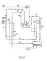
- 1 is a main heat exchanger for partially condensing the feed gas mixture
- 2 is a gas/liquid separator
- 3 is a distillation column having a rectification section 3a and a stripping section 3b
- 4 is an expansion turbine
- 5 is an expansion valve
- 6 and 7 are secondary heat exchangers
- 8 is a reboiler for the distillation column
- 9 is a pump for NGL product
- 10 is a two-stage compressor.
- Feed gas mixture is supplied to the plant in line 11 e.g. at 40 bar pressure, and generally at about ambient temperature. A first part of this feed is cooled and partially condensed in heat exchanger 1 and then passed via line 12 to gas/liquid separator 2 where the uncondensed gas is separated from the condensate.
- the uncondensed gas in line 13 is expanded through expansion turbine 4 to cause partial liquefaction and the partially liquefied gas is then fed to rectifying section 3a of the column 3.
- the rectified gas recovered from the top of the column in line 14 is passed back via line 15 to heat exchanger 1 where it passes in indirect counter-current heat exchange with the feed gas mixture in line 11 to cool and partially condense it.
- the gas is thereafter recompressed to the desired delivery pressure in compressor 10 and recovered through line 16 as sales gas.
- the liquid formed by the partial condensation is recovered from gas/liquid separator 2 in line 17, expanded in valve 5 to column pressure and fed to the stripping section 3b of the column 3.
- the desired product e.g. NGL
- the desired product is recovered from the column bottom in line 18.
- a part of this product is re-vaporised in heat exchanger 7 and reboiler 8 and returned to the column as reboil, the remainder is pumped to line 20 for recovery as NGL product.
- the heat medium for heat exchanger 7 and also for side reboiler 6, where this is used, is provided from a second part of the feed gas mixture which is thereafter passed to join the first part of the feed gas mixture downstream of heat exchanger 1 in line 12.
- the power requirement of the process was 1800 BHP.
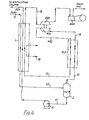
- a feed gas having the same composition as that described above and at the same pressure of about 40 bar is admitted to heat exchanger 1 through line 11 at about ambient temperature and cooled to about -40°C with returning product streams the nature of which are described more fully below.
- the feed is separated in gas/liquid separator 2 and the uncondensed gas in line 13 passed upwards in passages of refluxing exchanger 103 where it is further cooled by refrigerant passing through line 31 and the nature of which is described in more detail below with reference to Figure 3.
- the condensate formed by this further cooling descends in line 13 in direct counter-current with and in intimate contact with the rising gas and returns to the gas/liquid separator 2 where it mixes with the condensate therein.
- the gas recovered from the top of refluxing exchanger 103 in line 14 contains very little propane and virtually no heavier hydrocarbons and is typically at a temperature of about -70°C. This gas is passed back through further passages of the heat exchanger at the warm end thereof in line 15 and thence back through heat exchanger 1 from which it is withdrawn as sales gas through line 16 at substantially the same pressure as that at which the feed gas mixture is supplied.
- the liquid in separator 2, containing condensate formed in the refluxing exchanger 103, is recovered through line 17 and pumped back through exchanger 1 by pump 9. Leaving the exchanger at near-ambient temperature, it is fed to the top of stripper column 203 and the gas stripped from the liquid therein is recovered in line 21, typically at about 35°C, and returned to feed line 11.
- the stripped liquid is recovered from the bottom of the column in line 18, typically at about 95 0 C.
- a first part is returned through reboiler 8 to the bottom of the column and the remainder is recovered through line 20 as NGL product.
- Reboiler 8 which typically reheats the bottoms product to about 90-120°C, is suitably heated with hot oil or low pressure steam.
- the refrigerant in line 31 comprises evaporating working medium in the primary loop of a two-stage vapour compression cascade refrigerator as illustrated in Figure 3.
- primary refrigerant is compressed in compressor 301
- the compressed refrigerant is cooled and condensed in heat exchanger 302, expanded through expansion valve 303 and passed to gas/liquid separator 304.
- Any gas remaining uncondensed is recovered through line 32 and returned to compressor 301 for recompression and recycle.
- the condensate is transferred from the gas/liquid separator 304 to line 31 where it is evaporated in indirect heat exchange with the process stream in line 13 in refluxing exchanger 103 (see Figure 2).
- the evaporated medium is thereafter passed to line 32 for return, with any uncondensed gas from gas/liquid separator 304, to compressor 301.
- the condensation of the primary refrigerant medium in heat exchanger 302 is effected by indirect heat exchange with evaporating secondary medium in line 33.
- This secondary medium is then returned via lines 34 and 35 to compressor 305 where it is recompressed, cooled in heat exchanger 306 and condensed, expanded through expansion valve 307 and passed to gas/liquid separator 308 from which the condensate is recovered and passed to line 33 for evaporation in heat exchanger 302 as previously described.
- heat exchanger 1 If additional refrigeration is required in heat exchanger 1 (see Figure 2) this may conveniently be provided by diverting a part of the condensate formed in gas/liquid separator 308 to line 36 (shown as a broken line in Figure 3) for evaporation in heat exchanger 1 in indirect heat exchange relationship with the feed gas mixture in line 11. The evaporated medium is then returned to join line 35 for recompression in compressor 305 and recycle.
- the primary refrigerant may suitably be ethane or ethylene, for example, and the secondary refrigerant propane.
- the secondary refrigerant propane may suitably be ethane or ethylene, for example, and the secondary refrigerant propane.
- other refrigerants having suitable bubble and dew points may be employed, including mixed refrigerants.
- the refrigeration was provided using ethylene in the primary (i.e. low) temperature loop of the cascade refrigerator at a flow rate of 2390m 3 /hr with the high pressure side at 20 bar absolute and the low pressure side at 4.4 bar absolute, and propane in the secondary loop at a flow rate of 4130m 3 /hr with the high pressure side at 17.5 bar absolute and the low pressure side at 1.4 bar absolute. About 33% of the propane was passed through line 36 to provide additional refrigeration for the heat exchanger 1.
- the two-stage cascade refrigerator employed in the process described in Figure 2 may be replaced by some other form of external refrigeration, if desired.
- a single loop vapour compression refrigerator employing a mixed refrigerant may be employed but the power saving will not be so great.
- a process as described with reference to Figure 4 and operated to produce NGL and Sales Gas having the same flow rates and compositions as described in Table 1, and at the same delivery pressures, from the feed gas mixture described in Table 1 and provided at the same temperature and pressure and at the same flow rate as described above with reference to Figure 1 required 230 BHP refrigeration compression to supply that part of the required refrigeration provided by evaporating propane through line 36, and 920 BHP for recompressing the gas in compressors 403 (at 70% efficiency) and 404 of which 150 BHP was provided by turbine expander 401, at an expander efficiency of 78%, making a net total power requirement of 1000 BHP.
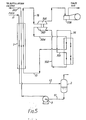
- FIG 5 is a flow diagram of part of an arrangement for a process according to the invention wherein all the refrigeration is provided by expansion of the uncondensed gas.
- the apparatus and process lines which are common to the arrangement in Figures 2 and 3 are identified by the same reference numerals.
- the operation of this arrangement is the same as that of Figures 2 and 3 except that in this arrangement, the uncondensed gas recovered in line 14 from refluxing exchanger 103 is first passed back in line 501 as a refrigerant stream for the warm end of the said exchanger, and then is passed via line 502 to turbine expander 503 where it is work expanded and cooled and the expanded gas is then passed in line 504 as refrigerant for the cold end of exchanger 103.
Applications Claiming Priority (4)
| Application Number | Priority Date | Filing Date | Title |
|---|---|---|---|
| GB8325069 | 1983-09-20 | ||
| GB8325069 | 1983-09-20 | ||
| GB08419488A GB2146751B (en) | 1983-09-20 | 1984-07-31 | Separation of hydrocarbon mixtures |
| GB8419488 | 1984-07-31 |
Publications (4)
| Publication Number | Publication Date |
|---|---|
| EP0137744A2 true EP0137744A2 (de) | 1985-04-17 |
| EP0137744A3 EP0137744A3 (en) | 1986-05-28 |
| EP0137744B1 EP0137744B1 (de) | 1988-11-09 |
| EP0137744B2 EP0137744B2 (de) | 1991-08-28 |
Family
ID=26286857
Family Applications (1)
| Application Number | Title | Priority Date | Filing Date |
|---|---|---|---|
| EP84306243A Expired EP0137744B2 (de) | 1983-09-20 | 1984-09-12 | Trennung von Kohlenwasserstoffgemischen |
Country Status (6)
| Country | Link |
|---|---|
| US (1) | US4622053A (de) |
| EP (1) | EP0137744B2 (de) |
| JP (1) | JPS6096686A (de) |
| AU (1) | AU572890B2 (de) |
| CA (1) | CA1245546A (de) |
| DE (2) | DE3475101D1 (de) |
Cited By (3)
| Publication number | Priority date | Publication date | Assignee | Title |
|---|---|---|---|---|
| EP0767351A2 (de) * | 1995-10-03 | 1997-04-09 | Air Products And Chemicals, Inc. | Stripping von leichten Komponenten in Rippenplatten-Wärmetauschern |
| EP2654913A1 (de) * | 2010-12-23 | 2013-10-30 | L'Air Liquide Société Anonyme pour l'Etude et l'Exploitation des Procédés Georges Claude | Verfahren und vorrichtung zur kondensation einer ersten kohlendioxidreichen flüssigkeit mittels einer zweiten flüssigkeit |
| KR20190040231A (ko) * | 2016-08-12 | 2019-04-17 | 린데 악티엔게젤샤프트 | 두 개의 탄소 원자를 가진 탄화수소를 주로 포함하는 분리 생성물 회수방법 및 설비 |
Families Citing this family (19)
| Publication number | Priority date | Publication date | Assignee | Title |
|---|---|---|---|---|
| US4734115A (en) * | 1986-03-24 | 1988-03-29 | Air Products And Chemicals, Inc. | Low pressure process for C3+ liquids recovery from process product gas |
| US4695303A (en) * | 1986-07-08 | 1987-09-22 | Mcdermott International, Inc. | Method for recovery of natural gas liquids |
| US4721164A (en) * | 1986-09-04 | 1988-01-26 | Air Products And Chemicals, Inc. | Method of heat exchange for variable-content nitrogen rejection units |
| GB2224036B (en) * | 1988-10-21 | 1992-06-24 | Costain Eng Ltd | Separation of gas & oil mixtures |
| US5035732A (en) * | 1990-01-04 | 1991-07-30 | Stone & Webster Engineering Corporation | Cryogenic separation of gaseous mixtures |
| JP2637611B2 (ja) * | 1990-07-04 | 1997-08-06 | 三菱重工業株式会社 | Nglまたはlpgの回収方法 |
| US5287703A (en) * | 1991-08-16 | 1994-02-22 | Air Products And Chemicals, Inc. | Process for the recovery of C2 + or C3 + hydrocarbons |
| US5983665A (en) * | 1998-03-03 | 1999-11-16 | Air Products And Chemicals, Inc. | Production of refrigerated liquid methane |
| MY136353A (en) * | 2003-02-10 | 2008-09-30 | Shell Int Research | Removing natural gas liquids from a gaseous natural gas stream |
| EP1695951B1 (de) * | 2003-07-24 | 2014-08-27 | Toyo Engineering Corporation | Verfahren und vorrichtung zur abtrennung von kohlenwasserstoffen |
| US7219682B2 (en) * | 2004-08-26 | 2007-05-22 | Seaone Maritime Corp. | Liquid displacement shuttle system and method |
| US7607310B2 (en) * | 2004-08-26 | 2009-10-27 | Seaone Maritime Corp. | Storage of natural gas in liquid solvents and methods to absorb and segregate natural gas into and out of liquid solvents |
| HUE050052T2 (hu) * | 2005-07-08 | 2020-11-30 | Seaone Holdings Llc | Eljárás gáz folyékony közegben történõ ömlesztett szállítására és tárolására |
| US20070130991A1 (en) * | 2005-12-14 | 2007-06-14 | Chevron U.S.A. Inc. | Liquefaction of associated gas at moderate conditions |
| JP2008002742A (ja) * | 2006-06-21 | 2008-01-10 | Daikin Ind Ltd | 冷凍装置 |
| US20080314079A1 (en) * | 2007-06-19 | 2008-12-25 | Air Products And Chemicals, Inc. | Nitrogen Rejection Column Reboiler Configuration |
| US10780955B2 (en) | 2008-06-20 | 2020-09-22 | Seaone Holdings, Llc | Comprehensive system for the storage and transportation of natural gas in a light hydrocarbon liquid medium |
| JP5875808B2 (ja) * | 2011-09-20 | 2016-03-02 | エア・ウォーター株式会社 | 高圧天然ガスの分離方法およびそれに用いる分離装置 |
| JP6527714B2 (ja) * | 2015-02-25 | 2019-06-05 | レール・リキード−ソシエテ・アノニム・プール・レテュード・エ・レクスプロワタシオン・デ・プロセデ・ジョルジュ・クロード | 液体燃料ガスの供給装置および供給方法 |
Citations (2)
| Publication number | Priority date | Publication date | Assignee | Title |
|---|---|---|---|---|
| US3436925A (en) * | 1965-09-21 | 1969-04-08 | Linde Ag | Rectification of liquefied coke oven gas portion by contact between liquefied and revaporized portions thereof |
| FR2345412A1 (fr) * | 1976-03-26 | 1977-10-21 | Snam Progetti | Procede de fractionnement de gaz de craquage, par refrigeration, dans les installations de fabrication de l'ethylene |
Family Cites Families (4)
| Publication number | Priority date | Publication date | Assignee | Title |
|---|---|---|---|---|
| DE1768460C2 (de) * | 1968-05-16 | 1973-01-04 | Badische Anilin- & Soda-Fabrik Ag, 6700 Ludwigshafen | Verfahren zur Gewinnung von Acetylen, Äthylen und höhere Kohlenwasserstoffe enthaltenden Gemischen aus Spaltgasen |
| US4266958A (en) * | 1978-07-17 | 1981-05-12 | Dut Pty Limited | Simultaneous cooling and removal of water from hydrocarbon gas mixtures |
| GB2110808B (en) * | 1981-11-24 | 1985-04-17 | Shell Int Research | Cryogenic gas plant |
| US4519825A (en) * | 1983-04-25 | 1985-05-28 | Air Products And Chemicals, Inc. | Process for recovering C4 + hydrocarbons using a dephlegmator |
-
1984
- 1984-09-12 EP EP84306243A patent/EP0137744B2/de not_active Expired
- 1984-09-12 AU AU32951/84A patent/AU572890B2/en not_active Ceased
- 1984-09-12 DE DE8484306243T patent/DE3475101D1/de not_active Expired
- 1984-09-12 DE DE198484306243T patent/DE137744T1/de active Pending
- 1984-09-14 US US06/650,724 patent/US4622053A/en not_active Expired - Lifetime
- 1984-09-20 CA CA000463692A patent/CA1245546A/en not_active Expired
- 1984-09-20 JP JP59195869A patent/JPS6096686A/ja active Granted
Patent Citations (2)
| Publication number | Priority date | Publication date | Assignee | Title |
|---|---|---|---|---|
| US3436925A (en) * | 1965-09-21 | 1969-04-08 | Linde Ag | Rectification of liquefied coke oven gas portion by contact between liquefied and revaporized portions thereof |
| FR2345412A1 (fr) * | 1976-03-26 | 1977-10-21 | Snam Progetti | Procede de fractionnement de gaz de craquage, par refrigeration, dans les installations de fabrication de l'ethylene |
Cited By (5)
| Publication number | Priority date | Publication date | Assignee | Title |
|---|---|---|---|---|
| EP0767351A2 (de) * | 1995-10-03 | 1997-04-09 | Air Products And Chemicals, Inc. | Stripping von leichten Komponenten in Rippenplatten-Wärmetauschern |
| EP0767351A3 (de) * | 1995-10-03 | 1997-07-09 | Air Prod & Chem | Stripping von leichten Komponenten in Rippenplatten-Wärmetauschern |
| EP2654913A1 (de) * | 2010-12-23 | 2013-10-30 | L'Air Liquide Société Anonyme pour l'Etude et l'Exploitation des Procédés Georges Claude | Verfahren und vorrichtung zur kondensation einer ersten kohlendioxidreichen flüssigkeit mittels einer zweiten flüssigkeit |
| EP2654913B1 (de) * | 2010-12-23 | 2022-02-16 | L'Air Liquide Société Anonyme pour l'Etude et l'Exploitation des Procédés Georges Claude | Verfahren und vorrichtung zur kondensation einer ersten kohlendioxidreichen flüssigkeit mittels einer zweiten flüssigkeit |
| KR20190040231A (ko) * | 2016-08-12 | 2019-04-17 | 린데 악티엔게젤샤프트 | 두 개의 탄소 원자를 가진 탄화수소를 주로 포함하는 분리 생성물 회수방법 및 설비 |
Also Published As
| Publication number | Publication date |
|---|---|
| EP0137744B1 (de) | 1988-11-09 |
| DE3475101D1 (en) | 1988-12-15 |
| US4622053A (en) | 1986-11-11 |
| DE137744T1 (de) | 1986-10-16 |
| CA1245546A (en) | 1988-11-29 |
| AU3295184A (en) | 1985-03-28 |
| AU572890B2 (en) | 1988-05-19 |
| EP0137744B2 (de) | 1991-08-28 |
| EP0137744A3 (en) | 1986-05-28 |
| JPS6096686A (ja) | 1985-05-30 |
| JPH0552875B2 (de) | 1993-08-06 |
Similar Documents
| Publication | Publication Date | Title |
|---|---|---|
| EP0137744B1 (de) | Trennung von Kohlenwasserstoffgemischen | |
| US5291736A (en) | Method of liquefaction of natural gas | |
| US6125653A (en) | LNG with ethane enrichment and reinjection gas as refrigerant | |
| US3205669A (en) | Recovery of natural gas liquids, helium concentrate, and pure nitrogen | |
| US4720293A (en) | Process for the recovery and purification of ethylene | |
| US7204100B2 (en) | Natural gas liquefaction | |
| JP4452239B2 (ja) | 炭化水素の分離方法および分離装置 | |
| US7069744B2 (en) | Lean reflux-high hydrocarbon recovery process | |
| US5275005A (en) | Gas processing | |
| US4203742A (en) | Process for the recovery of ethane and heavier hydrocarbon components from methane-rich gases | |
| US11365933B2 (en) | Systems and methods for LNG production with propane and ethane recovery | |
| US5983665A (en) | Production of refrigerated liquid methane | |
| MX2007015226A (es) | Procesamiento de gases de hidrocarburos. | |
| JP2004534116A (ja) | 天然ガスの低温処理におけるlng製造法 | |
| EP1620687A2 (de) | Behandlung von kohlenwasserstoffgasen | |
| EP1144929A1 (de) | Verbessertes verfahren zur rückgewinnung von methan | |
| US4331461A (en) | Cryogenic separation of lean and rich gas streams | |
| US6425266B1 (en) | Low temperature hydrocarbon gas separation process | |
| US4846863A (en) | Separation of hydrocarbon mixtures | |
| GB2146751A (en) | Separation of hydrocarbon mixtures | |
| US5768913A (en) | Process based mixed refrigerants for ethylene plants | |
| US11643604B2 (en) | Hydrocarbon gas processing | |
| US20210131728A1 (en) | Process and apparatus for separating hydrocarbon | |
| US20210116174A1 (en) | Hydrocarbon gas processing |
Legal Events
| Date | Code | Title | Description |
|---|---|---|---|
| PUAI | Public reference made under article 153(3) epc to a published international application that has entered the european phase |
Free format text: ORIGINAL CODE: 0009012 |
|
| AK | Designated contracting states |
Designated state(s): BE DE FR IT NL |
|
| PUAL | Search report despatched |
Free format text: ORIGINAL CODE: 0009013 |
|
| AK | Designated contracting states |
Kind code of ref document: A3 Designated state(s): BE DE FR IT NL |
|
| ITCL | It: translation for ep claims filed |
Representative=s name: ING. A. GIAMBROCONO & C. S.R.L. |
|
| EL | Fr: translation of claims filed | ||
| TCNL | Nl: translation of patent claims filed | ||
| DET | De: translation of patent claims | ||
| 17P | Request for examination filed |
Effective date: 19861024 |
|
| 17Q | First examination report despatched |
Effective date: 19871109 |
|
| GRAA | (expected) grant |
Free format text: ORIGINAL CODE: 0009210 |
|
| AK | Designated contracting states |
Kind code of ref document: B1 Designated state(s): BE DE FR IT NL |
|
| ITF | It: translation for a ep patent filed |
Owner name: ING. A. GIAMBROCONO & C. S.R.L. |
|
| REF | Corresponds to: |
Ref document number: 3475101 Country of ref document: DE Date of ref document: 19881215 |
|
| ET | Fr: translation filed | ||
| PLBI | Opposition filed |
Free format text: ORIGINAL CODE: 0009260 |
|
| 26 | Opposition filed |
Opponent name: AIR PRODUCTS AND CHEMICALS INC. Effective date: 19890809 |
|
| NLR1 | Nl: opposition has been filed with the epo |
Opponent name: AIR PRODUCTS AND CHEMICALS INC. |
|
| PUAH | Patent maintained in amended form |
Free format text: ORIGINAL CODE: 0009272 |
|
| STAA | Information on the status of an ep patent application or granted ep patent |
Free format text: STATUS: PATENT MAINTAINED AS AMENDED |
|
| 27A | Patent maintained in amended form |
Effective date: 19910828 |
|
| AK | Designated contracting states |
Kind code of ref document: B2 Designated state(s): BE DE FR IT NL |
|
| ITTA | It: last paid annual fee | ||
| NLR2 | Nl: decision of opposition | ||
| ET3 | Fr: translation filed ** decision concerning opposition | ||
| ITF | It: translation for a ep patent filed |
Owner name: ING. A. GIAMBROCONO & C. S.R.L. |
|
| NLR3 | Nl: receipt of modified translations in the netherlands language after an opposition procedure | ||
| BECH | Be: change of holder |
Free format text: 920918 *COSTAIN OIL, GAS AND PROCESS LTD;*DUT PTY LTD |
|
| REG | Reference to a national code |
Ref country code: FR Ref legal event code: TP |
|
| ITPR | It: changes in ownership of a european patent |
Owner name: CESSIONE;COSTAIN OIL, GAS AND PROCESS LIMITED |
|
| NLT1 | Nl: modifications of names registered in virtue of documents presented to the patent office pursuant to art. 16 a, paragraph 1 |
Owner name: COSTAIN ENGINEERING LIMITED TE MANCHESTER, GROOT-B |
|
| NLS | Nl: assignments of ep-patents |
Owner name: COSTAIN OIL, GAS AND PROCESS LIMITED TE LONDEN, GR |
|
| PGFP | Annual fee paid to national office [announced via postgrant information from national office to epo] |
Ref country code: NL Payment date: 19960930 Year of fee payment: 13 Ref country code: BE Payment date: 19960930 Year of fee payment: 13 |
|
| PG25 | Lapsed in a contracting state [announced via postgrant information from national office to epo] |
Ref country code: BE Free format text: LAPSE BECAUSE OF NON-PAYMENT OF DUE FEES Effective date: 19970930 |
|
| BERE | Be: lapsed |
Owner name: DUT PTY LTD Effective date: 19970930 Owner name: GAS AND PROCESS LTD Effective date: 19970930 Owner name: COSTAIN OIL Effective date: 19970930 |
|
| PG25 | Lapsed in a contracting state [announced via postgrant information from national office to epo] |
Ref country code: NL Free format text: LAPSE BECAUSE OF NON-PAYMENT OF DUE FEES Effective date: 19980401 |
|
| NLV4 | Nl: lapsed or anulled due to non-payment of the annual fee |
Effective date: 19980401 |
|
| PGFP | Annual fee paid to national office [announced via postgrant information from national office to epo] |
Ref country code: FR Payment date: 20000928 Year of fee payment: 17 |
|
| PGFP | Annual fee paid to national office [announced via postgrant information from national office to epo] |
Ref country code: DE Payment date: 20001030 Year of fee payment: 17 |
|
| PG25 | Lapsed in a contracting state [announced via postgrant information from national office to epo] |
Ref country code: DE Free format text: LAPSE BECAUSE OF NON-PAYMENT OF DUE FEES Effective date: 20020501 |
|
| PG25 | Lapsed in a contracting state [announced via postgrant information from national office to epo] |
Ref country code: FR Free format text: LAPSE BECAUSE OF NON-PAYMENT OF DUE FEES Effective date: 20020531 |
|
| REG | Reference to a national code |
Ref country code: FR Ref legal event code: ST |