EP0137733A2 - Vorrichtung zum Steuern der Ansauglufttemperatur für Brennkraftmaschine - Google Patents
Vorrichtung zum Steuern der Ansauglufttemperatur für Brennkraftmaschine Download PDFInfo
- Publication number
- EP0137733A2 EP0137733A2 EP84306184A EP84306184A EP0137733A2 EP 0137733 A2 EP0137733 A2 EP 0137733A2 EP 84306184 A EP84306184 A EP 84306184A EP 84306184 A EP84306184 A EP 84306184A EP 0137733 A2 EP0137733 A2 EP 0137733A2
- Authority
- EP
- European Patent Office
- Prior art keywords
- air
- chamber
- bleed passage
- actuator
- control device
- Prior art date
- Legal status (The legal status is an assumption and is not a legal conclusion. Google has not performed a legal analysis and makes no representation as to the accuracy of the status listed.)
- Granted
Links
Images

Classifications
-
- F—MECHANICAL ENGINEERING; LIGHTING; HEATING; WEAPONS; BLASTING
- F02—COMBUSTION ENGINES; HOT-GAS OR COMBUSTION-PRODUCT ENGINE PLANTS
- F02M—SUPPLYING COMBUSTION ENGINES IN GENERAL WITH COMBUSTIBLE MIXTURES OR CONSTITUENTS THEREOF
- F02M31/00—Apparatus for thermally treating combustion-air, fuel, or fuel-air mixture
- F02M31/02—Apparatus for thermally treating combustion-air, fuel, or fuel-air mixture for heating
- F02M31/04—Apparatus for thermally treating combustion-air, fuel, or fuel-air mixture for heating combustion-air or fuel-air mixture
- F02M31/06—Apparatus for thermally treating combustion-air, fuel, or fuel-air mixture for heating combustion-air or fuel-air mixture by hot gases, e.g. by mixing cold and hot air
-
- Y—GENERAL TAGGING OF NEW TECHNOLOGICAL DEVELOPMENTS; GENERAL TAGGING OF CROSS-SECTIONAL TECHNOLOGIES SPANNING OVER SEVERAL SECTIONS OF THE IPC; TECHNICAL SUBJECTS COVERED BY FORMER USPC CROSS-REFERENCE ART COLLECTIONS [XRACs] AND DIGESTS
- Y02—TECHNOLOGIES OR APPLICATIONS FOR MITIGATION OR ADAPTATION AGAINST CLIMATE CHANGE
- Y02T—CLIMATE CHANGE MITIGATION TECHNOLOGIES RELATED TO TRANSPORTATION
- Y02T10/00—Road transport of goods or passengers
- Y02T10/10—Internal combustion engine [ICE] based vehicles
- Y02T10/12—Improving ICE efficiencies
Definitions
- This invention relates to air temperature control devices for internal combustion engines. Such devices are well-known; they are used in an attempt to provide the engine air intake with air at a temperature appropriate to the operating conditions prevailing at a particular time. These operating conditions include such parameters as throttle setting, engine temperature and ambient air temperature.
- Air temperature control devices together with some preferred operational features are described in for example Patent Specifications GB1126157, GB1313434 and GB1361728.
- bimetallic strips and other thermo-responsive devices to actuate air valves of various kinds, either directly or through a servomotor.
- an air temperature control device for the air intake system of an internal combustion engine comprises a thermo- responsive actuator which is, in use, disposed to respond to the air temperature in said intake system, a first valve means operably connected to the actuator for progressive movement in a first chamber provided with an air inlet and/or outlet ports between two positions, in the first of which positions a first bleed passage from the chamber is closed and in the second of which positions said bleed passage is open permitting the passage of air to or from said ports to or from a second chamber provided a port which is connected, in use, to a vacuum motor operable to adjust the relative proportions of ambient and pre-heated air admitted to the intake system, and a second valve means engageable with the first valve means to close said bleed passage, third valve means operable to close a second bleed passage between said second chamber and a third chamber having an air outlet connected, in use, to the engine air intake manifold, said second bleed passage being defined in a pressure-responsive wall member separating said second and third chambers.
- the pressure responsive wall member is preferably a diaphragm and the second valve means is preferably a poppet valve mounted thereon and biased so as to close said second bleed passage, for example by means of a spring.
- the first valve means and the associated thermo-responsive actuator are preferably biased towards closure of the first bleed passage, with the actuator in its fully retracted cold state.
- the air temperature control device is preferably provided with means for limiting the movement of the pressure responsive wall member in the direction of the air outlet.
- the air outlet from the third chamber preferably incorporates a restriction, the purpose-of which is to ensure that there is still a pressure drop when the actuator has opened the first valve means.
- This pressure drop serves to create a pressure intermediate that in the first chamber and that due to the vacuum source, namely the engine vacuum at the carburettor throat.
- the restriction may be achieved by selection of pipe size and/or length, but it will usually be more convenient to include a conventional narrow orifice, at the point of connection to the sensor, for example.
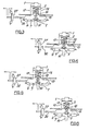
- the device comprises a thermo-responsive actuator 1 of the wax pellet type. This is seated on a housing 14 which constitutes the side wall of a first chamber provided with a plurality of ports 12.
- the first chamber is closed by a bottom wall 15 having a central tubular upstand 5 provided with an aperture 16 which constitutes a first bleed passage from the chamber.
- the actuator 1 has a piston 2; a compression spring 4 biases the latter away from the bottom wall 15 towards its fully retracted state.
- the piston carries a bleed valve member 17 which extends into the tubular upstand 5 and has a sealing surface 3 adapted to seat against the rim of the upstand when the actuator is fully retracted.
- Air bleed passageways 13 extend through the member 17 and communicate with a downwardly facing port 18 located in a second chamber constituted by a peripheral flange portion of the wall 15 and a diaphragm 6.
- the central area of the latter is provided with an aperture containing the lower portion of a non-return poppet value 7 biased by a spring 8 to close the aperture.
- the second chamber has also a vacuum motor pipe connection port 11.
- the upper portion of the poppet valve is of complementary shape to that of the downwardly facing port 18 in the bleed valve member 17.
- a third chamber 18 is constituted by a bottom plate 19 crimped around the peripheral portions of the wall 15 and the diaphragm 6 to hold the assembly together.
- the bottom plate has an air outlet pipe 10 and an annular recess 9 which serves to limit the extent of movement of the oentre of the diaphragm 6 towards the bottom wall.
- the sensor has been deliberately shown in figure 1 with the actuator 1 in a ⁇ partially-operated state.
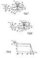
- the device of figure 1 is mounted with the actuator 1 inside an internal combustion engine air intake passage 21 between the throttle valve 22 of a carburettor 23, and an air cleaner 24.
- the air cleaner is supplied with air from two sources, one a source of pre-heated air, 25, the other a source of ambient air, 26.
- a vacuum servomotor 27 is provided to operate a flap valve 28 which enables the relative proportions of air from the two sources to be adjusted between the extremes of all hot pre-heated air and all-ambient temperature air.
- the vacuum motor is connected by a pipe 29 to the pipe connection 11 of figure 1.
- the air outlet pipe 10 of figure 1 is connected to a vacuum source constituted by a pipe 30 tapped into the carburettor throat downstream of the throttle valve 22.
- FIGS. 3 to 8 inclusive show the system of figure 2 at various engine/ambient temperatures, with throttle settings in the closed (over-run) to partially open range and alse under full throttle conditions.
- figure 3 is the completely cold start condition.
- the bleed valve member 17 sealing surface 3 is seated against the rim of the upstand 5 and the reduced pressure in the second chamber is applied only to the servomotor 27 through the pipe connection 11.
- the servomotor moves the flap valve 28 to close off the ambient source 26, so that all intake air is drawn from the pre-heated source 25.
- application of full throttle to the cold system reduces the vacuum in the third chamber 18 and allows the poppet valve 7 to close.
- the reduced pressure thereby trapped in the second chamber lifts the diaphragm upwardly off the apex of recess 9 until the upper portion of the poppet valve hits the margins of the downwardly facing port 18 in the bleed valve member 17. This momentarily unseats the poppet valve and allows at least some equalisation of the pressures above and below the diaghragm before the poppet valve seats again.
- the stiffness against upward movement of the diaphragm 6 gives the sensor the characteristics of a pressure regulator under full throttle conditions.
- the final pressure differential across the diaphragm will be a function of the clearance between the lower margin of port 18 and the lower (rest) position of the poppet value 7; it will therefore vary inversely with the degree of extension of the actuator 1.
- the net effect is a slight reduction in the vacuum applied to the servomotor so that some ambient . air is allowed to enter the intake to increase engine power.
- the device is as depicted in the partially warmed-up condition achieved when pre-heated air has caused the actuator 1 to operate, pushing the piston and bleed valve member 17 down against the spring 4.
- the sealing surface 3 unseats from the rim of the upstand 5, allowing air to bleed into the second chamber from the intake passage via ports 12, 13 and 18.
- This further reduces the vacuum developed under light (or olosed) throttle conditions and the servomotor admits more ambient air.
- the cooling effect of the latter on the actuator 1 is such that the position of the actuator will depend very largely on the ambient temperature, once the system is throughly warmed up.
- low ambient temperatures typically below 7 °c
- very little ambient air is needed to maintain a desired air intake temperature of say 25 to 30 °c.
- the higher the ambient temperature the greater the proportion of ambient air needed to achieve/maintain the desired air intake temperature, of course.
- the actuator When the engine is warm and the ambient air temperature is high, the actuator is fully operated as shown in fugure 7 and the vacuum in the second chamber is minimal, so that the servomotor hardly operates.
- the air intake is therefore predominantly all at ambient temperature.
- the diaphragm Under the figure 8 full throttle condition the diaphragm has only to rise very slightly to unseat the poppet valve, so that the increase in pressure (fall in vacuum in the throat 31) is communicated to the servomotor, ensuring that the latter closes off the pre-heated air source to give maximum engine power by virtue of admitting only ambient air to the air cleaner.
- Figure 10 shows the actuator-movement as a function of temperature corresponding to the three conditions (1,2 and 3 on the graph) represented by the three pairs of figures, namely figures and 4, 5 and 6 and 7 and 8 respectively.
Applications Claiming Priority (2)
| Application Number | Priority Date | Filing Date | Title |
|---|---|---|---|
| GB08324598A GB2146385B (en) | 1983-09-14 | 1983-09-14 | Controlling temperature of air supplied to i c engines |
| GB8324598 | 1983-09-14 |
Publications (3)
| Publication Number | Publication Date |
|---|---|
| EP0137733A2 true EP0137733A2 (de) | 1985-04-17 |
| EP0137733A3 EP0137733A3 (en) | 1985-11-13 |
| EP0137733B1 EP0137733B1 (de) | 1987-11-19 |
Family
ID=10548767
Family Applications (1)
| Application Number | Title | Priority Date | Filing Date |
|---|---|---|---|
| EP84306184A Expired EP0137733B1 (de) | 1983-09-14 | 1984-09-11 | Vorrichtung zum Steuern der Ansauglufttemperatur für Brennkraftmaschine |
Country Status (5)
| Country | Link |
|---|---|
| US (1) | US4572147A (de) |
| EP (1) | EP0137733B1 (de) |
| DE (1) | DE3467602D1 (de) |
| ES (1) | ES535889A0 (de) |
| GB (1) | GB2146385B (de) |
Cited By (1)
| Publication number | Priority date | Publication date | Assignee | Title |
|---|---|---|---|---|
| GB2213910A (en) * | 1987-12-21 | 1989-08-23 | Coopers Ap Filters Ltd | Air temperature control device |
Citations (2)
| Publication number | Priority date | Publication date | Assignee | Title |
|---|---|---|---|---|
| GB2001414A (en) * | 1977-07-21 | 1979-01-31 | Toyota Motor Co Ltd | Thermostatic valves for intake air temperature compensation for internal combustion engines |
| US4244343A (en) * | 1978-02-20 | 1981-01-13 | Nippondenso Co., Ltd. | Thermostatic valve for compensating air fuel mixture for air temperature change |
Family Cites Families (5)
| Publication number | Priority date | Publication date | Assignee | Title |
|---|---|---|---|---|
| GB1091553A (en) * | 1964-01-14 | 1967-11-15 | Tatra Np | Improvements in or relating to fluid control valves |
| US3394687A (en) * | 1966-04-08 | 1968-07-30 | Dole Valve Co | Temperature responsive control |
| JPS5611653Y2 (de) * | 1977-01-27 | 1981-03-17 | ||
| DE2816727C2 (de) * | 1978-04-18 | 1982-03-25 | Filterwerk Mann & Hummel Gmbh, 7140 Ludwigsburg | Vorrichtung zur Regelung der Temperatur der Ansaugluft von gemischverdichtenden Brennkraftmaschinen |
| US4416416A (en) * | 1979-11-13 | 1983-11-22 | Eaton Corporation | Two-port thermally responsive valve |
-
1983
- 1983-09-14 GB GB08324598A patent/GB2146385B/en not_active Expired
-
1984
- 1984-09-11 DE DE8484306184T patent/DE3467602D1/de not_active Expired
- 1984-09-11 EP EP84306184A patent/EP0137733B1/de not_active Expired
- 1984-09-13 US US06/650,081 patent/US4572147A/en not_active Expired - Fee Related
- 1984-09-13 ES ES535889A patent/ES535889A0/es active Granted
Patent Citations (2)
| Publication number | Priority date | Publication date | Assignee | Title |
|---|---|---|---|---|
| GB2001414A (en) * | 1977-07-21 | 1979-01-31 | Toyota Motor Co Ltd | Thermostatic valves for intake air temperature compensation for internal combustion engines |
| US4244343A (en) * | 1978-02-20 | 1981-01-13 | Nippondenso Co., Ltd. | Thermostatic valve for compensating air fuel mixture for air temperature change |
Cited By (2)
| Publication number | Priority date | Publication date | Assignee | Title |
|---|---|---|---|---|
| GB2213910A (en) * | 1987-12-21 | 1989-08-23 | Coopers Ap Filters Ltd | Air temperature control device |
| GB2213910B (en) * | 1987-12-21 | 1992-01-08 | Coopers Ap Filters Ltd | Air temperature control apparatus |
Also Published As
| Publication number | Publication date |
|---|---|
| US4572147A (en) | 1986-02-25 |
| ES8506858A1 (es) | 1985-07-16 |
| DE3467602D1 (en) | 1987-12-23 |
| ES535889A0 (es) | 1985-07-16 |
| GB2146385A (en) | 1985-04-17 |
| GB2146385B (en) | 1987-07-29 |
| EP0137733A3 (en) | 1985-11-13 |
| GB8324598D0 (en) | 1983-10-19 |
| EP0137733B1 (de) | 1987-11-19 |
Similar Documents
| Publication | Publication Date | Title |
|---|---|---|
| US3830210A (en) | Air intake system with temperature-controlled warm air valve | |
| US4069798A (en) | Pressure transducer and exhaust gas recirculation control valve using same | |
| US4231343A (en) | Device for controlling the intake air temperature of a carburetor-equipped internal combustion engine | |
| US4244343A (en) | Thermostatic valve for compensating air fuel mixture for air temperature change | |
| US4286433A (en) | Control system for turbocharger | |
| US4522181A (en) | Fuel injection pump for internal combustion engines | |
| US4175524A (en) | Inlet air temperature control for automobile engine | |
| EP0137733B1 (de) | Vorrichtung zum Steuern der Ansauglufttemperatur für Brennkraftmaschine | |
| US4573441A (en) | Valve arrangement | |
| US4365608A (en) | Controlling engine exhaust gas recirculation and vacuum inverter | |
| US4126110A (en) | Inlet air temperature control for an I.C. engine | |
| US4208994A (en) | Thermally responsive valve | |
| US3963042A (en) | Internal combustion engine control system and improved pneumatically operated temperature controlled valve construction therefor or the like | |
| JPS5924856Y2 (ja) | 内燃機関の吸入空気温度補償用サ−モスタテイツクバルブ | |
| GB2096239A (en) | Regulation of i c engine idling speed by throttle bypass valve control | |
| US4016853A (en) | Control system and improved pneumatically operated temperature controlled valve construction therefor or the like | |
| JPS5848442Y2 (ja) | 温度感知弁 | |
| US4064894A (en) | Vacuum reducer valve | |
| US4231336A (en) | Exhaust gas recirculation system for an internal combustion engine | |
| JPS6021273B2 (ja) | 熱応動流体制御弁 | |
| US4218040A (en) | Valve positioner and method of making same | |
| US3789815A (en) | Temperature responsive control device | |
| US4261317A (en) | Anti-after burn system for internal combustion engine | |
| EP0666413B1 (de) | Abgasrückführungssystem | |
| GB2146386A (en) | Control of temperature of air supplied to I.C. engines |
Legal Events
| Date | Code | Title | Description |
|---|---|---|---|
| PUAI | Public reference made under article 153(3) epc to a published international application that has entered the european phase |
Free format text: ORIGINAL CODE: 0009012 |
|
| AK | Designated contracting states |
Designated state(s): BE DE FR IT SE |
|
| PUAL | Search report despatched |
Free format text: ORIGINAL CODE: 0009013 |
|
| AK | Designated contracting states |
Designated state(s): BE DE FR IT SE |
|
| 17P | Request for examination filed |
Effective date: 19850917 |
|
| 17Q | First examination report despatched |
Effective date: 19860605 |
|
| ITF | It: translation for a ep patent filed |
Owner name: BARZANO' E ZANARDO ROMA S.P.A. |
|
| GRAA | (expected) grant |
Free format text: ORIGINAL CODE: 0009210 |
|
| AK | Designated contracting states |
Kind code of ref document: B1 Designated state(s): BE DE FR IT SE |
|
| REF | Corresponds to: |
Ref document number: 3467602 Country of ref document: DE Date of ref document: 19871223 |
|
| ET | Fr: translation filed | ||
| PLBE | No opposition filed within time limit |
Free format text: ORIGINAL CODE: 0009261 |
|
| STAA | Information on the status of an ep patent application or granted ep patent |
Free format text: STATUS: NO OPPOSITION FILED WITHIN TIME LIMIT |
|
| 26N | No opposition filed | ||
| PG25 | Lapsed in a contracting state [announced via postgrant information from national office to epo] |
Ref country code: SE Effective date: 19890912 |
|
| PG25 | Lapsed in a contracting state [announced via postgrant information from national office to epo] |
Ref country code: BE Effective date: 19890930 |
|
| BERE | Be: lapsed |
Owner name: COOPERS FILTERS LTD Effective date: 19890930 |
|
| PG25 | Lapsed in a contracting state [announced via postgrant information from national office to epo] |
Ref country code: FR Effective date: 19900531 |
|
| PG25 | Lapsed in a contracting state [announced via postgrant information from national office to epo] |
Ref country code: DE Effective date: 19900601 |
|
| REG | Reference to a national code |
Ref country code: FR Ref legal event code: ST |
|
| EUG | Se: european patent has lapsed |
Ref document number: 84306184.7 Effective date: 19900521 |