EP0137683B1 - Verhinderung der Bohrflüssigkeitsverluste in unterirdischen Formationen - Google Patents
Verhinderung der Bohrflüssigkeitsverluste in unterirdischen Formationen Download PDFInfo
- Publication number
- EP0137683B1 EP0137683B1 EP84305788A EP84305788A EP0137683B1 EP 0137683 B1 EP0137683 B1 EP 0137683B1 EP 84305788 A EP84305788 A EP 84305788A EP 84305788 A EP84305788 A EP 84305788A EP 0137683 B1 EP0137683 B1 EP 0137683B1
- Authority
- EP
- European Patent Office
- Prior art keywords
- oil
- drilling fluid
- acid
- drilling
- loss reducer
- Prior art date
- Legal status (The legal status is an assumption and is not a legal conclusion. Google has not performed a legal analysis and makes no representation as to the accuracy of the status listed.)
- Expired
Links
- 238000005553 drilling Methods 0.000 title claims description 115
- 230000015572 biosynthetic process Effects 0.000 title claims description 35
- 238000005755 formation reaction Methods 0.000 title description 32
- 230000002265 prevention Effects 0.000 title description 2
- 239000012530 fluid Substances 0.000 claims description 82
- 238000000034 method Methods 0.000 claims description 43
- 239000003638 chemical reducing agent Substances 0.000 claims description 40
- 239000002585 base Substances 0.000 claims description 35
- BPQQTUXANYXVAA-UHFFFAOYSA-N Orthosilicate Chemical compound [O-][Si]([O-])([O-])[O-] BPQQTUXANYXVAA-UHFFFAOYSA-N 0.000 claims description 34
- 235000014113 dietary fatty acids Nutrition 0.000 claims description 32
- 239000000194 fatty acid Substances 0.000 claims description 32
- 229930195729 fatty acid Natural products 0.000 claims description 32
- 150000004665 fatty acids Chemical class 0.000 claims description 32
- VYPSYNLAJGMNEJ-UHFFFAOYSA-N Silicium dioxide Chemical compound O=[Si]=O VYPSYNLAJGMNEJ-UHFFFAOYSA-N 0.000 claims description 31
- 239000000203 mixture Substances 0.000 claims description 24
- 239000003921 oil Substances 0.000 claims description 22
- XLYOFNOQVPJJNP-UHFFFAOYSA-N water Substances O XLYOFNOQVPJJNP-UHFFFAOYSA-N 0.000 claims description 21
- 239000000344 soap Substances 0.000 claims description 18
- QGZKDVFQNNGYKY-UHFFFAOYSA-O Ammonium Chemical compound [NH4+] QGZKDVFQNNGYKY-UHFFFAOYSA-O 0.000 claims description 17
- 239000003795 chemical substances by application Substances 0.000 claims description 17
- 229910000272 alkali metal oxide Inorganic materials 0.000 claims description 16
- 239000007788 liquid Substances 0.000 claims description 16
- 239000000377 silicon dioxide Substances 0.000 claims description 15
- 235000012239 silicon dioxide Nutrition 0.000 claims description 15
- 239000003995 emulsifying agent Substances 0.000 claims description 13
- LQJBNNIYVWPHFW-UHFFFAOYSA-N 20:1omega9c fatty acid Natural products CCCCCCCCCCC=CCCCCCCCC(O)=O LQJBNNIYVWPHFW-UHFFFAOYSA-N 0.000 claims description 11
- ZQPPMHVWECSIRJ-KTKRTIGZSA-N oleic acid Chemical compound CCCCCCCC\C=C/CCCCCCCC(O)=O ZQPPMHVWECSIRJ-KTKRTIGZSA-N 0.000 claims description 10
- WRIDQFICGBMAFQ-UHFFFAOYSA-N (E)-8-Octadecenoic acid Natural products CCCCCCCCCC=CCCCCCCC(O)=O WRIDQFICGBMAFQ-UHFFFAOYSA-N 0.000 claims description 9
- QSBYPNXLFMSGKH-UHFFFAOYSA-N 9-Heptadecensaeure Natural products CCCCCCCC=CCCCCCCCC(O)=O QSBYPNXLFMSGKH-UHFFFAOYSA-N 0.000 claims description 9
- 239000005642 Oleic acid Substances 0.000 claims description 9
- ZQPPMHVWECSIRJ-UHFFFAOYSA-N Oleic acid Natural products CCCCCCCCC=CCCCCCCCC(O)=O ZQPPMHVWECSIRJ-UHFFFAOYSA-N 0.000 claims description 9
- 150000001768 cations Chemical class 0.000 claims description 9
- QXJSBBXBKPUZAA-UHFFFAOYSA-N isooleic acid Natural products CCCCCCCC=CCCCCCCCCC(O)=O QXJSBBXBKPUZAA-UHFFFAOYSA-N 0.000 claims description 9
- DGAQECJNVWCQMB-PUAWFVPOSA-M Ilexoside XXIX Chemical compound C[C@@H]1CC[C@@]2(CC[C@@]3(C(=CC[C@H]4[C@]3(CC[C@@H]5[C@@]4(CC[C@@H](C5(C)C)OS(=O)(=O)[O-])C)C)[C@@H]2[C@]1(C)O)C)C(=O)O[C@H]6[C@@H]([C@H]([C@@H]([C@H](O6)CO)O)O)O.[Na+] DGAQECJNVWCQMB-PUAWFVPOSA-M 0.000 claims description 8
- 150000004760 silicates Chemical class 0.000 claims description 8
- 239000011734 sodium Substances 0.000 claims description 8
- 229910052708 sodium Inorganic materials 0.000 claims description 8
- ZLMJMSJWJFRBEC-UHFFFAOYSA-N Potassium Chemical compound [K] ZLMJMSJWJFRBEC-UHFFFAOYSA-N 0.000 claims description 7
- 125000004432 carbon atom Chemical group C* 0.000 claims description 7
- 239000002283 diesel fuel Substances 0.000 claims description 7
- 239000011591 potassium Substances 0.000 claims description 7
- 229910052700 potassium Inorganic materials 0.000 claims description 7
- 229910052783 alkali metal Inorganic materials 0.000 claims description 6
- 150000001340 alkali metals Chemical class 0.000 claims description 6
- SECPZKHBENQXJG-FPLPWBNLSA-N palmitoleic acid Chemical compound CCCCCC\C=C/CCCCCCCC(O)=O SECPZKHBENQXJG-FPLPWBNLSA-N 0.000 claims description 6
- 150000001408 amides Chemical class 0.000 claims description 5
- 150000001412 amines Chemical class 0.000 claims description 5
- 239000010779 crude oil Substances 0.000 claims description 5
- VTYYLEPIZMXCLO-UHFFFAOYSA-L Calcium carbonate Chemical compound [Ca+2].[O-]C([O-])=O VTYYLEPIZMXCLO-UHFFFAOYSA-L 0.000 claims description 4
- POULHZVOKOAJMA-UHFFFAOYSA-N dodecanoic acid Chemical compound CCCCCCCCCCCC(O)=O POULHZVOKOAJMA-UHFFFAOYSA-N 0.000 claims description 4
- 239000002480 mineral oil Substances 0.000 claims description 4
- 235000010446 mineral oil Nutrition 0.000 claims description 4
- UQSXHKLRYXJYBZ-UHFFFAOYSA-N Iron oxide Chemical compound [Fe]=O UQSXHKLRYXJYBZ-UHFFFAOYSA-N 0.000 claims description 3
- 235000021319 Palmitoleic acid Nutrition 0.000 claims description 3
- DTOSIQBPPRVQHS-PDBXOOCHSA-N alpha-linolenic acid Chemical compound CC\C=C/C\C=C/C\C=C/CCCCCCCC(O)=O DTOSIQBPPRVQHS-PDBXOOCHSA-N 0.000 claims description 3
- 235000020661 alpha-linolenic acid Nutrition 0.000 claims description 3
- SECPZKHBENQXJG-UHFFFAOYSA-N cis-palmitoleic acid Natural products CCCCCCC=CCCCCCCCC(O)=O SECPZKHBENQXJG-UHFFFAOYSA-N 0.000 claims description 3
- 239000003502 gasoline Substances 0.000 claims description 3
- 229960004488 linolenic acid Drugs 0.000 claims description 3
- KQQKGWQCNNTQJW-UHFFFAOYSA-N linolenic acid Natural products CC=CCCC=CCC=CCCCCCCCC(O)=O KQQKGWQCNNTQJW-UHFFFAOYSA-N 0.000 claims description 3
- 239000003129 oil well Substances 0.000 claims description 3
- WBHHMMIMDMUBKC-XLNAKTSKSA-N ricinelaidic acid Chemical compound CCCCCC[C@@H](O)C\C=C\CCCCCCCC(O)=O WBHHMMIMDMUBKC-XLNAKTSKSA-N 0.000 claims description 3
- 229960003656 ricinoleic acid Drugs 0.000 claims description 3
- FEUQNCSVHBHROZ-UHFFFAOYSA-N ricinoleic acid Natural products CCCCCCC(O[Si](C)(C)C)CC=CCCCCCCCC(=O)OC FEUQNCSVHBHROZ-UHFFFAOYSA-N 0.000 claims description 3
- CUXYLFPMQMFGPL-UHFFFAOYSA-N (9Z,11E,13E)-9,11,13-Octadecatrienoic acid Natural products CCCCC=CC=CC=CCCCCCCCC(O)=O CUXYLFPMQMFGPL-UHFFFAOYSA-N 0.000 claims description 2
- OYHQOLUKZRVURQ-NTGFUMLPSA-N (9Z,12Z)-9,10,12,13-tetratritiooctadeca-9,12-dienoic acid Chemical compound C(CCCCCCC\C(=C(/C\C(=C(/CCCCC)\[3H])\[3H])\[3H])\[3H])(=O)O OYHQOLUKZRVURQ-NTGFUMLPSA-N 0.000 claims description 2
- DPUOLQHDNGRHBS-UHFFFAOYSA-N Brassidinsaeure Natural products CCCCCCCCC=CCCCCCCCCCCCC(O)=O DPUOLQHDNGRHBS-UHFFFAOYSA-N 0.000 claims description 2
- URXZXNYJPAJJOQ-UHFFFAOYSA-N Erucic acid Natural products CCCCCCC=CCCCCCCCCCCCC(O)=O URXZXNYJPAJJOQ-UHFFFAOYSA-N 0.000 claims description 2
- 239000005639 Lauric acid Substances 0.000 claims description 2
- CUXYLFPMQMFGPL-SUTYWZMXSA-N all-trans-octadeca-9,11,13-trienoic acid Chemical compound CCCC\C=C\C=C\C=C\CCCCCCCC(O)=O CUXYLFPMQMFGPL-SUTYWZMXSA-N 0.000 claims description 2
- DPUOLQHDNGRHBS-KTKRTIGZSA-N erucic acid Chemical compound CCCCCCCC\C=C/CCCCCCCCCCCC(O)=O DPUOLQHDNGRHBS-KTKRTIGZSA-N 0.000 claims description 2
- LQJBNNIYVWPHFW-QXMHVHEDSA-N gadoleic acid Chemical compound CCCCCCCCCC\C=C/CCCCCCCC(O)=O LQJBNNIYVWPHFW-QXMHVHEDSA-N 0.000 claims description 2
- FATBGEAMYMYZAF-KTKRTIGZSA-N oleamide Chemical compound CCCCCCCC\C=C/CCCCCCCC(N)=O FATBGEAMYMYZAF-KTKRTIGZSA-N 0.000 claims description 2
- 229960002969 oleic acid Drugs 0.000 claims description 2
- 229940113162 oleylamide Drugs 0.000 claims description 2
- TZCXTZWJZNENPQ-UHFFFAOYSA-L barium sulfate Chemical group [Ba+2].[O-]S([O-])(=O)=O TZCXTZWJZNENPQ-UHFFFAOYSA-L 0.000 claims 1
- 229910052601 baryte Inorganic materials 0.000 claims 1
- 239000010428 baryte Substances 0.000 claims 1
- 229910000019 calcium carbonate Inorganic materials 0.000 claims 1
- 229940033355 lauric acid Drugs 0.000 claims 1
- 238000012360 testing method Methods 0.000 description 21
- 235000019198 oils Nutrition 0.000 description 18
- 239000002245 particle Substances 0.000 description 18
- 239000000243 solution Substances 0.000 description 12
- 230000018044 dehydration Effects 0.000 description 11
- 238000006297 dehydration reaction Methods 0.000 description 11
- 239000000463 material Substances 0.000 description 10
- 239000004111 Potassium silicate Substances 0.000 description 6
- NNHHDJVEYQHLHG-UHFFFAOYSA-N potassium silicate Chemical compound [K+].[K+].[O-][Si]([O-])=O NNHHDJVEYQHLHG-UHFFFAOYSA-N 0.000 description 6
- 229910052913 potassium silicate Inorganic materials 0.000 description 6
- 235000019353 potassium silicate Nutrition 0.000 description 6
- LFQSCWFLJHTTHZ-UHFFFAOYSA-N Ethanol Chemical compound CCO LFQSCWFLJHTTHZ-UHFFFAOYSA-N 0.000 description 5
- 238000001694 spray drying Methods 0.000 description 5
- TWRXJAOTZQYOKJ-UHFFFAOYSA-L Magnesium chloride Chemical compound [Mg+2].[Cl-].[Cl-] TWRXJAOTZQYOKJ-UHFFFAOYSA-L 0.000 description 4
- 239000002253 acid Substances 0.000 description 4
- 150000007513 acids Chemical class 0.000 description 4
- 229940056585 ammonium laurate Drugs 0.000 description 4
- VJCJAQSLASCYAW-UHFFFAOYSA-N azane;dodecanoic acid Chemical compound [NH4+].CCCCCCCCCCCC([O-])=O VJCJAQSLASCYAW-UHFFFAOYSA-N 0.000 description 4
- 239000000839 emulsion Substances 0.000 description 4
- 239000000706 filtrate Substances 0.000 description 4
- 238000010438 heat treatment Methods 0.000 description 4
- 238000006703 hydration reaction Methods 0.000 description 4
- 239000000843 powder Substances 0.000 description 4
- 229920006395 saturated elastomer Polymers 0.000 description 4
- 238000003756 stirring Methods 0.000 description 4
- VHUUQVKOLVNVRT-UHFFFAOYSA-N Ammonium hydroxide Chemical compound [NH4+].[OH-] VHUUQVKOLVNVRT-UHFFFAOYSA-N 0.000 description 3
- OYPRJOBELJOOCE-UHFFFAOYSA-N Calcium Chemical compound [Ca] OYPRJOBELJOOCE-UHFFFAOYSA-N 0.000 description 3
- KFZMGEQAYNKOFK-UHFFFAOYSA-N Isopropanol Chemical compound CC(C)O KFZMGEQAYNKOFK-UHFFFAOYSA-N 0.000 description 3
- WHXSMMKQMYFTQS-UHFFFAOYSA-N Lithium Chemical compound [Li] WHXSMMKQMYFTQS-UHFFFAOYSA-N 0.000 description 3
- OKKJLVBELUTLKV-UHFFFAOYSA-N Methanol Chemical compound OC OKKJLVBELUTLKV-UHFFFAOYSA-N 0.000 description 3
- 239000008186 active pharmaceutical agent Substances 0.000 description 3
- 239000000908 ammonium hydroxide Substances 0.000 description 3
- 239000011575 calcium Substances 0.000 description 3
- 229910052791 calcium Inorganic materials 0.000 description 3
- 239000012141 concentrate Substances 0.000 description 3
- 238000001816 cooling Methods 0.000 description 3
- 238000005520 cutting process Methods 0.000 description 3
- 239000011521 glass Substances 0.000 description 3
- 229930195733 hydrocarbon Natural products 0.000 description 3
- 150000002430 hydrocarbons Chemical class 0.000 description 3
- 230000002706 hydrostatic effect Effects 0.000 description 3
- 229910052744 lithium Inorganic materials 0.000 description 3
- OFBQJSOFQDEBGM-UHFFFAOYSA-N n-pentane Natural products CCCCC OFBQJSOFQDEBGM-UHFFFAOYSA-N 0.000 description 3
- 239000007787 solid Substances 0.000 description 3
- CSCPPACGZOOCGX-UHFFFAOYSA-N Acetone Chemical compound CC(C)=O CSCPPACGZOOCGX-UHFFFAOYSA-N 0.000 description 2
- UXVMQQNJUSDDNG-UHFFFAOYSA-L Calcium chloride Chemical compound [Cl-].[Cl-].[Ca+2] UXVMQQNJUSDDNG-UHFFFAOYSA-L 0.000 description 2
- 239000004215 Carbon black (E152) Substances 0.000 description 2
- RYGMFSIKBFXOCR-UHFFFAOYSA-N Copper Chemical compound [Cu] RYGMFSIKBFXOCR-UHFFFAOYSA-N 0.000 description 2
- 206010016803 Fluid overload Diseases 0.000 description 2
- FYYHWMGAXLPEAU-UHFFFAOYSA-N Magnesium Chemical compound [Mg] FYYHWMGAXLPEAU-UHFFFAOYSA-N 0.000 description 2
- LRHPLDYGYMQRHN-UHFFFAOYSA-N N-Butanol Chemical compound CCCCO LRHPLDYGYMQRHN-UHFFFAOYSA-N 0.000 description 2
- WCUXLLCKKVVCTQ-UHFFFAOYSA-M Potassium chloride Chemical compound [Cl-].[K+] WCUXLLCKKVVCTQ-UHFFFAOYSA-M 0.000 description 2
- ATUOYWHBWRKTHZ-UHFFFAOYSA-N Propane Chemical compound CCC ATUOYWHBWRKTHZ-UHFFFAOYSA-N 0.000 description 2
- 239000004115 Sodium Silicate Substances 0.000 description 2
- FAPWRFPIFSIZLT-UHFFFAOYSA-M Sodium chloride Chemical compound [Na+].[Cl-] FAPWRFPIFSIZLT-UHFFFAOYSA-M 0.000 description 2
- 239000000654 additive Substances 0.000 description 2
- 230000008901 benefit Effects 0.000 description 2
- 238000009835 boiling Methods 0.000 description 2
- 239000001110 calcium chloride Substances 0.000 description 2
- 229910001628 calcium chloride Inorganic materials 0.000 description 2
- 150000001875 compounds Chemical class 0.000 description 2
- 230000001276 controlling effect Effects 0.000 description 2
- 229910052802 copper Inorganic materials 0.000 description 2
- 239000010949 copper Substances 0.000 description 2
- 238000002425 crystallisation Methods 0.000 description 2
- 230000008025 crystallization Effects 0.000 description 2
- DIOQZVSQGTUSAI-UHFFFAOYSA-N decane Chemical compound CCCCCCCCCC DIOQZVSQGTUSAI-UHFFFAOYSA-N 0.000 description 2
- 230000000694 effects Effects 0.000 description 2
- 238000001914 filtration Methods 0.000 description 2
- 239000008398 formation water Substances 0.000 description 2
- 239000007789 gas Substances 0.000 description 2
- 230000036571 hydration Effects 0.000 description 2
- 239000011777 magnesium Substances 0.000 description 2
- 229910052749 magnesium Inorganic materials 0.000 description 2
- 229910001629 magnesium chloride Inorganic materials 0.000 description 2
- 238000002156 mixing Methods 0.000 description 2
- 238000001556 precipitation Methods 0.000 description 2
- 238000002360 preparation method Methods 0.000 description 2
- 230000008569 process Effects 0.000 description 2
- 239000011435 rock Substances 0.000 description 2
- 150000004671 saturated fatty acids Chemical class 0.000 description 2
- 235000003441 saturated fatty acids Nutrition 0.000 description 2
- 238000007789 sealing Methods 0.000 description 2
- NTHWMYGWWRZVTN-UHFFFAOYSA-N sodium silicate Chemical compound [Na+].[Na+].[O-][Si]([O-])=O NTHWMYGWWRZVTN-UHFFFAOYSA-N 0.000 description 2
- 229910052911 sodium silicate Inorganic materials 0.000 description 2
- XZPVPNZTYPUODG-UHFFFAOYSA-M sodium;chloride;dihydrate Chemical compound O.O.[Na+].[Cl-] XZPVPNZTYPUODG-UHFFFAOYSA-M 0.000 description 2
- 239000007921 spray Substances 0.000 description 2
- 239000000126 substance Substances 0.000 description 2
- 235000021122 unsaturated fatty acids Nutrition 0.000 description 2
- 150000004670 unsaturated fatty acids Chemical class 0.000 description 2
- POAOYUHQDCAZBD-UHFFFAOYSA-N 2-butoxyethanol Chemical compound CCCCOCCO POAOYUHQDCAZBD-UHFFFAOYSA-N 0.000 description 1
- 235000021357 Behenic acid Nutrition 0.000 description 1
- OYHQOLUKZRVURQ-HZJYTTRNSA-N Linoleic acid Chemical compound CCCCC\C=C/C\C=C/CCCCCCCC(O)=O OYHQOLUKZRVURQ-HZJYTTRNSA-N 0.000 description 1
- 235000021360 Myristic acid Nutrition 0.000 description 1
- 235000021314 Palmitic acid Nutrition 0.000 description 1
- XUIMIQQOPSSXEZ-UHFFFAOYSA-N Silicon Chemical compound [Si] XUIMIQQOPSSXEZ-UHFFFAOYSA-N 0.000 description 1
- 235000021355 Stearic acid Nutrition 0.000 description 1
- 230000000996 additive effect Effects 0.000 description 1
- 230000002411 adverse Effects 0.000 description 1
- 238000005054 agglomeration Methods 0.000 description 1
- 230000002776 aggregation Effects 0.000 description 1
- 238000013019 agitation Methods 0.000 description 1
- 239000002199 base oil Substances 0.000 description 1
- 239000012267 brine Substances 0.000 description 1
- 239000001273 butane Substances 0.000 description 1
- 235000010216 calcium carbonate Nutrition 0.000 description 1
- -1 caproleic Chemical class 0.000 description 1
- 239000003054 catalyst Substances 0.000 description 1
- 230000008859 change Effects 0.000 description 1
- 238000006243 chemical reaction Methods 0.000 description 1
- 239000003240 coconut oil Substances 0.000 description 1
- 235000019864 coconut oil Nutrition 0.000 description 1
- 235000009508 confectionery Nutrition 0.000 description 1
- 230000007797 corrosion Effects 0.000 description 1
- 238000005260 corrosion Methods 0.000 description 1
- 235000012343 cottonseed oil Nutrition 0.000 description 1
- 239000002385 cottonseed oil Substances 0.000 description 1
- 239000013078 crystal Substances 0.000 description 1
- 239000002270 dispersing agent Substances 0.000 description 1
- 239000006185 dispersion Substances 0.000 description 1
- 238000004090 dissolution Methods 0.000 description 1
- UKMSUNONTOPOIO-UHFFFAOYSA-N docosanoic acid Chemical class CCCCCCCCCCCCCCCCCCCCCC(O)=O UKMSUNONTOPOIO-UHFFFAOYSA-N 0.000 description 1
- 239000002657 fibrous material Substances 0.000 description 1
- 238000007710 freezing Methods 0.000 description 1
- 230000008014 freezing Effects 0.000 description 1
- 239000013505 freshwater Substances 0.000 description 1
- 239000000295 fuel oil Substances 0.000 description 1
- 239000003349 gelling agent Substances 0.000 description 1
- 159000000011 group IA salts Chemical class 0.000 description 1
- 150000008282 halocarbons Chemical class 0.000 description 1
- 210000003128 head Anatomy 0.000 description 1
- 230000002209 hydrophobic effect Effects 0.000 description 1
- 150000002500 ions Chemical class 0.000 description 1
- 235000013980 iron oxide Nutrition 0.000 description 1
- VBMVTYDPPZVILR-UHFFFAOYSA-N iron(2+);oxygen(2-) Chemical class [O-2].[Fe+2] VBMVTYDPPZVILR-UHFFFAOYSA-N 0.000 description 1
- 239000003350 kerosene Substances 0.000 description 1
- 235000020778 linoleic acid Nutrition 0.000 description 1
- OYHQOLUKZRVURQ-IXWMQOLASA-N linoleic acid Natural products CCCCC\C=C/C\C=C\CCCCCCCC(O)=O OYHQOLUKZRVURQ-IXWMQOLASA-N 0.000 description 1
- 238000005461 lubrication Methods 0.000 description 1
- 239000000696 magnetic material Substances 0.000 description 1
- 238000004519 manufacturing process Methods 0.000 description 1
- 230000004048 modification Effects 0.000 description 1
- 238000012986 modification Methods 0.000 description 1
- IJDNQMDRQITEOD-UHFFFAOYSA-N n-butane Chemical compound CCCC IJDNQMDRQITEOD-UHFFFAOYSA-N 0.000 description 1
- IPCSVZSSVZVIGE-UHFFFAOYSA-N palmitic acid group Chemical group C(CCCCCCCCCCCCCCC)(=O)O IPCSVZSSVZVIGE-UHFFFAOYSA-N 0.000 description 1
- 238000009931 pascalization Methods 0.000 description 1
- 230000035515 penetration Effects 0.000 description 1
- 230000035699 permeability Effects 0.000 description 1
- 239000003208 petroleum Substances 0.000 description 1
- 239000004033 plastic Substances 0.000 description 1
- 239000001103 potassium chloride Substances 0.000 description 1
- 235000011164 potassium chloride Nutrition 0.000 description 1
- 239000001294 propane Substances 0.000 description 1
- 230000035484 reaction time Effects 0.000 description 1
- 230000009467 reduction Effects 0.000 description 1
- 230000001105 regulatory effect Effects 0.000 description 1
- 229910052701 rubidium Inorganic materials 0.000 description 1
- IGLNJRXAVVLDKE-UHFFFAOYSA-N rubidium atom Chemical compound [Rb] IGLNJRXAVVLDKE-UHFFFAOYSA-N 0.000 description 1
- 239000012266 salt solution Substances 0.000 description 1
- 150000003839 salts Chemical class 0.000 description 1
- 238000010008 shearing Methods 0.000 description 1
- 229910052710 silicon Inorganic materials 0.000 description 1
- 239000010703 silicon Substances 0.000 description 1
- 239000011780 sodium chloride Substances 0.000 description 1
- HPALAKNZSZLMCH-UHFFFAOYSA-M sodium;chloride;hydrate Chemical compound O.[Na+].[Cl-] HPALAKNZSZLMCH-UHFFFAOYSA-M 0.000 description 1
- 239000003549 soybean oil Substances 0.000 description 1
- 235000012424 soybean oil Nutrition 0.000 description 1
- 238000010561 standard procedure Methods 0.000 description 1
- 238000003860 storage Methods 0.000 description 1
- 239000003784 tall oil Substances 0.000 description 1
- 239000003760 tallow Substances 0.000 description 1
- 239000012749 thinning agent Substances 0.000 description 1
Images
Classifications
-
- E—FIXED CONSTRUCTIONS
- E21—EARTH OR ROCK DRILLING; MINING
- E21B—EARTH OR ROCK DRILLING; OBTAINING OIL, GAS, WATER, SOLUBLE OR MELTABLE MATERIALS OR A SLURRY OF MINERALS FROM WELLS
- E21B21/00—Methods or apparatus for flushing boreholes, e.g. by use of exhaust air from motor
- E21B21/003—Means for stopping loss of drilling fluid
-
- C—CHEMISTRY; METALLURGY
- C09—DYES; PAINTS; POLISHES; NATURAL RESINS; ADHESIVES; COMPOSITIONS NOT OTHERWISE PROVIDED FOR; APPLICATIONS OF MATERIALS NOT OTHERWISE PROVIDED FOR
- C09K—MATERIALS FOR MISCELLANEOUS APPLICATIONS, NOT PROVIDED FOR ELSEWHERE
- C09K8/00—Compositions for drilling of boreholes or wells; Compositions for treating boreholes or wells, e.g. for completion or for remedial operations
- C09K8/02—Well-drilling compositions
- C09K8/32—Non-aqueous well-drilling compositions, e.g. oil-based
-
- Y—GENERAL TAGGING OF NEW TECHNOLOGICAL DEVELOPMENTS; GENERAL TAGGING OF CROSS-SECTIONAL TECHNOLOGIES SPANNING OVER SEVERAL SECTIONS OF THE IPC; TECHNICAL SUBJECTS COVERED BY FORMER USPC CROSS-REFERENCE ART COLLECTIONS [XRACs] AND DIGESTS
- Y02—TECHNOLOGIES OR APPLICATIONS FOR MITIGATION OR ADAPTATION AGAINST CLIMATE CHANGE
- Y02P—CLIMATE CHANGE MITIGATION TECHNOLOGIES IN THE PRODUCTION OR PROCESSING OF GOODS
- Y02P20/00—Technologies relating to chemical industry
- Y02P20/141—Feedstock
-
- Y—GENERAL TAGGING OF NEW TECHNOLOGICAL DEVELOPMENTS; GENERAL TAGGING OF CROSS-SECTIONAL TECHNOLOGIES SPANNING OVER SEVERAL SECTIONS OF THE IPC; TECHNICAL SUBJECTS COVERED BY FORMER USPC CROSS-REFERENCE ART COLLECTIONS [XRACs] AND DIGESTS
- Y10—TECHNICAL SUBJECTS COVERED BY FORMER USPC
- Y10S—TECHNICAL SUBJECTS COVERED BY FORMER USPC CROSS-REFERENCE ART COLLECTIONS [XRACs] AND DIGESTS
- Y10S507/00—Earth boring, well treating, and oil field chemistry
- Y10S507/91—Earth boring fluid devoid of discrete aqueous phase
Definitions
- the present invention relates to the prevention of drilling fluid loss in subterranean formations and, more particularly, to a method of limiting and localizing the penetration of an oil-base drilling fluid into porous underground strata, crevices, and fissures during the drilling of a well in a permeable subterranean formation.
- a drill bit In the drilling of a well into the earth by rotary drilling techniques, a drill bit is attached to a drill string and the drill bit is rotated in contact with the earth to cut and break the earth and form a well therein.
- a drilling fluid is circulated between the surface of the earth and the bottom of the well to remove drill cuttings therefrom, lubricate the bit and drill string, and to apply hydrostatic pressure to the well to control the flow of fluids into the well from the earth formation penetrated by the well.
- Drilling fluids commonly employed include gaseous and liquid drilling fluids.
- Liquid drilling fluids often called “drilling muds”
- Oil base fluids commonly include a minor portion of water present in the oil as an emulsion of the water-in-oil (invert) type.
- Oil base drilling fluids are generally more expensive than water-base drilling fluids. Nevertheless, they have a number of advantages thereover. Thus, oil base fluids prevent formation damage to water sensitive reservoirs and prevent hole enlargement and permit coring in water-soluble rocks, such as salt. In addition, oil base drilling fluids maintain stable mud properties in deep and high temperature holes which require heavy mud. Further, these fluids prevent corrosion of the drill pipe, casing, and tubing which reduces expensive workovers. The usually allow an increased drilling rate because of better lubrication and removal of the shell cuttings without disintegration of the cuttings. Another advantage with oil base drilling fluids is that they generally can be reclaimed for a later use and this reduces the overall cost.
- U.S. Patent 4,222,444 discloses the use of magnetic material to reduce the amount of drilling fluid lost to a formation.
- U.S. Patent 3,509,951 discloses the use of a wax emulsion to control the loss of a drilling fluid while drilling a well.
- fibrous materials have been used in drilling fluids in order to form a sheath on the formation surface and prevent the loss of the drilling fluid into the formation.
- a method of drilling an oil well in a subterranean formation having connate water containing monovalent and polyvalent cations which method comprises:
- the invention also includes a method wherein the seepage loss reducer is a powdered amorphous silicate having a molar ratio of silicon dioxide to alkali metal oxide in the range of from about 2.0:1 to about 2.7:1.
- the present invention provides a method of alleviating the loss of an oil-base drilling fluid into a subterranean formation that contains monovalent and polyvalent cations and is penetrated in the drilling of a well.
- the method has particular application in controlling partial lost circulation or seepage when drilling with oil-base fluids and is hereafter described with reference to such fluids.
- the oil-base drilling fluid used to carry out the method of the present invention has a density of from about 8.0 to about 25.0 pounds per U.S. gallon (960 to 3000 kg/m 3 ) and comprises an oil-base liquid comprising from about 60.0 to about 99.0 percent by volume of oil and from about 1 to about 40 percent by volume of water, a weighting agent present in an amount sufficient to produce a drilling fluid having the above density, from about 1.0 to about 9.0 percent by weight of an emulsifying agent (based on the combined weight of the oil-base liquid which comprises the oil and the water, and the weighting agent) and a seepage loss reducer.
- the seepage loss reducer used to carry out the method of the present invention is selected from the group consisting of a powdered silicate having a molar ratio of silicon dioxide to alkali metal oxide in the range of from about 1.5:1 to about 3.3:1 wherein the alkali metal is selected from the group consisting of sodium, potassium, and mixtures thereof, and an ammonium soap of a fatty acid having from about 12 to about 22 carbon atoms.
- the oil-base drilling fluid containing the seepage loss reducer is circulated in the well bore and the seepage loss reducer reacts with the monovalent and polyvalent cations such as sodium, magnesium, or calcium, in the subterranean formation to form a seal in the formation adjacent to the well bore.
- the silicate compounds that can be employed in the method described herein have a molar ratio of silicon dioxide to alkali metal oxide in the range of from about 1.5:1 to about 3.3: 1. To improve the sealing ability of the silicon dioxide, it is desirable to have a high ratio of silicon dioxide to alkali metal oxide. Such a high ratio also reduces the amount of alkali metal oxide that must be neutralized to produce gelling and sealing. Higher ratios are generally more difficult to dissolve.
- the molar ratio of silicon dioxide to alkali metal oxide in the range of from about 2.0:1 to about 2.7:1. Most preferably, the ratio of silicon dioxide to alkali metal oxide is maintained at a ratio of about 2.5:1. Silicates of such ratio have short dissolution times while still having relatively high silicon dioxide densities.
- the powdered silicate is preferably partially hydrated. Over-hydration or under-hydration, however, produces a less satisfactory powder. Over-hydration (more than about 20% water content by weight) produces amorphous particles which tend to flow and slowly convert to crystalline silicate which is slowly soluble. Under-hydration (less than about 12% water content by weight) results in particles which are crystalline initially and, therefore, are difficult to dissolve. Most preferably, the partially hydrated powdered silicate of the present invention has a water content in the range of from about 14% to about 16% by weight of the hydrated silicate. Amorphous particles with this hydration are relatively stable and are easily dissolved.
- the silicate of the present invention is preferably comprised of amorphous particles of the partially hydrated silicate. Crystalline particles are not readily dissolvable.
- silicates of the present invention either sodium or potassium or mixtures thereof can be utilized as the alkali metal in the silicate.
- the silicate of the present invention can be represented by the formula Si0 2 :M 2 0. As stated above, M is selected from the group consisting of sodium, potassium and mixtures thereof.
- Other alkali metals, such as lithium and rubidium are not suitable because of their significantly different properties.
- the first method consists of spray drying a silicate solution having a temperature less than 100°F (38°C).
- the spray drying produces a powder of amorphous glass particles.
- it allows production of a partially hydrated powdered silicate having a water content in the range of from about 14% to about 16% by weight of the hydrated silicate. As stated above, this range of partial hydration and the amorphosu glass quality of the particles have a significant effect upon the ability of the silicate to dissolve.
- a silicate solution having a desired ratio of silicon dioxide to alkali metal oxide in the range of from about 1.5:1 to about 3.3:1 is prepared and maintained at a temperature lower than 110°F (43°C) and preferably lower than 85°F (30°C).
- This solution is delivered to a spray drying device which produces rapid cooling and rapid dehydration of small droplets of the solution.
- the droplets pass from an equilibrium to a non-equilibrium state such that an easily soluble amorphous glass particle is formed.
- the cooling and dehydration must be rapid enough to prevent the silicate from being converted to a slowly soluble crystal state. If necessary, the solution can be refrigerated and the spray directed against a cooled baffle or the like.
- the second method of preparing the rapidly dissolvable powdered silicate also utilizes rapid dehydration at a relatively low temperature.
- dehydration is achieved by adding a dehydration agent to the silicate solution of the appropriate ratio.
- the solution must be maintained at a temperature less than 110°F (43°C) and preferably less than 85°F (30°C).
- Preferred dehydration agents include ethanol, methanol and acetone. Less suitable are isopropyl alcohol, butyl alcohol, and ethylene glycol monobutyl ether. Also less suitable are saturated salt solutions such as those of sodium chloride and potassium chloride.
- a dehydration agent such as ethanol
- ethanol is added to the silicate solution undergoing rapid shearing
- particles of partially hydrated amorphous silicate are precipitated from the silicate solution. These particles are separated from the liquid and then dried without heating. For example, additional alcohol can be added to the particles and then allowed to evaporate at room temperature.
- trace amounts of lithium and copper can be added to help prevent crystallization of the silicates.
- Lithium provides an undersized atomic particle and copper provides an oversized atomic particle to assist in breaking up crystalline patterns as they form.
- Other suitable undersized or oversized atomic particles can be utilized.
- the amorphous particles of the powdered silicate In order to be rapidly dissolvable, it is desirable to have the amorphous particles of the powdered silicate smaller than 40-mesh size. If a significant number, 10% for example, of particles are larger than 40-mesh size, field use is hampered. To arrive at a powder having less than 40-mesh size, the powder resulting from the preparation methods can be screened or ground until the appropriate size is achieved. Also, the particle size can be controlled in the formation process of spray dyring or precipitation with methods that are well known.
- the powdered silicate of the present invention By utilizing the powdered silicate of the present invention, an improved method of preventing leak-off into the formation of an oil-base drilling fluid is achieved.
- the powdered silicate can be stored at the well location prior to its use. Furthermore, the storage of the silicate can occur at temperature below freezing without adverse effect to the powdered silicate material.
- Potassium silicate is less reactive with calcium and other di- and polyvalent ions than sodium silicate, but gelling still results upon combination with a sufficient amount of these agents or a sufficient amount of reaction time.
- the slower gelling time and higher concentration of gelling agent or catalyst can, therefore, be utilized to produce gelling at a desired time or location where sodium silicate would not be suitable.
- the preferred seepage loss reducer is powdered silicate.
- the oil used in the drilling fluid of the present invention are well known in the art and include substantially all hydrocarbon materials such as crude oil, both sweet and sour, a partially refined fraction of crude oil (e.g. side cuts from crude columns, crude column overheads, gas oils, kerosene, heavy naphthas, naphthas, straight-run gasoline, liquified petroleum gases); refined fractions of crude oil (propane, butane, pentane, decane, etc.) and synthesized hydrocarbons including halogenated hydrocarbons.
- the hydrocarbon is preferably a partially refined fraction of crude oil (e.g. diesel fuel, mineral oil, or a gasoline cut-off of a crude column).
- the invention is not limited to any particular type of oil or mixtures thereof.
- an emulsifying agent is used to carry out the method of the present invention.
- the emulsifying agent comprises a fatty acid or an amine or an amide derivative of a fatty acid.
- emulsifying agents are disclosed in U.S. Patent 4,233,162 which is herein incorporated by reference.
- Specific examples of suitable saturated fatty acids are capric, lauric, myristic, palmitic, stearic, and behenic acids.
- Suitable unsaturated fatty acids are monoethenoid acids, such as caproleic, lauroleic, myristoleic, palmitoleic, oleic, and cetoleic acids, diethanoid acids, such as linoleic acid; and triethenoid acids, such as linolenic acid.
- monoethenoid acids such as caproleic, lauroleic, myristoleic, palmitoleic, oleic, and cetoleic acids
- diethanoid acids such as linoleic acid
- triethenoid acids such as linolenic acid.
- the emulsifying agent comprises a mixture of dimerized oleic acid, oleic acid and oleyl amide.
- Amine and amide derivatives of the fatty acids can be prepared by methods well known in the art.
- the amount of emulsifying agent used to carry out the method of the present invention will vary widely depending upon the make up of the oil-base drilling fluid, but will generally be in the range of about 0.1 to about 9.0 weight percent based on the combined weight of the oil-base liquid and weighting agent present in the oil-base drilling fluid to give the drilling fluid a density of about 8.0 to 25.0 pounds per U.S. gallon (960 to 3000 kg/m 3 ).
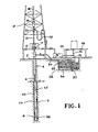
- numeral 4 designates a well bore drilled into the earth's surface (2) by a hollow drill string (6) drill bit (8) attached to the lower end of the drill string.
- the drill bit may be a rock bit or may be a drag bit or suitably may be one having rollers or conical cutters.
- the drill string (6) extends up the floor (10) of a derrick (12) through a rotary table (14) which is rotated by means not shown.
- the drill string is suspended by a block (16) hoisting lines (18) and swivel (20). Swivel (20) is connected by a flexible line (22) to a drilling mud pump (24).
- a suction line (26) which connects to a settling basin (28) divided into two parts by a weir (30).
- the drilling mud is introduced thereto by a return ditch (34) carrying any material resulting from the drilling operation.
- the section (32) is of sufficient size to provide a residence time for settling of the material as a layer (36) in the bottom of the basin (28).
- the drilling fluid flows by lines (22) and (26) down the hollow drill string (6) and out through the eyes (38) of the drill bit (8) and up the annulus (40) to the return ditch (34).
- the drilling fluid containing the seepage loss reducer is pumped by 15 drilling mud pump (24) through line (22) down the hollow drill string (6) into the bit (8).
- the drilling mud passes from the eyes (38) of the drill bit into the annulus (40).
- the fluid is maintained in the annulus (40) under sufficient pressure by the pump (24) to overcome the hydrostatic head of the connate water in the formation (42).
- the drilling fluid containing the seepage loss reducer comes in contact with the water in the formation (42) which contains monovalent and polyvalent cations such as sodium, potassium, calcium, and magnesium.
- the seepage loss reducer in the fluid upon contact with the water in the formation (42) forms a solid substance (44) adjacent to the well bore. Since the seepage loss reducer is used to form a seal (44), it is at times necessary to add the seepage loss reducer to replace that which is deposited as a seal (44).
- One manner of adding the seepage loss reduced to the drilling fluid is by line (46) which is connected to a tank (48) which contains the seepage loss reducer.
- the amount of the seepage loss reducer used in the drilling fluid will vary over a wide range depending upon the amount of connate water in the subterranean formation. Generally, however, one pound of seepage loss reducer per barrel (2.85 kg/m3) of oil-base drilling fluid to about 25 pounds of seepage loss reducer per barrel (71.25 kg/m 3 ) of oil-base drilling fluid is used to carry out the method of the invention with about 5 pounds to about 10 pounds of seepage loss reducer per barrel (14.25 to 28.5 kg/m 3 ) of oil-base drilling fluid being the more preferred amount of seepage loss reducer to use with the oil-base drilling fluid.
- a dispersing agent sometimes referred to as a thinning agent may be included to aiding and controlling the viscosity to better provide a pumpable mixture.
- a weighting material is employed to tailor the weight of the drilling fluid. Any conventional weighting material known in the art may be employed. Examples of suitable weighting agents include barites, iron oxides, and calcium carbonates. The weighting material is employed in an effective weighting amount which can vary depending on the composition of the drilliqg fluid and the desired density and characteristics of the drilling fluid. Sufficient weighting material is utilized to give a final drilling fluid density of from about 8.0 to about 25.0 pounds per U.S. gallon (960 to 3000 kg/m 3 ).
- the water component can be fresh water or a brine saturated or partially saturated with alkaline salts, such as calcium chloride or magnesium chloride.
- the seepage loss reducer which is either an ammonium soap of a fatty acid having about 12 to about 22 carbon atoms or a silicate is dispersed in the oil-base drilling fluid is not of primary importance, and if desired, the requisite amount of the seepage loss reducer may be simply added to the oil-base drilling fluid at ordinary temperatures while employing agitation or stirring to obtain a uniform drilling fluid. Additional materials, such as the emulisfying agent or weighting material can be added in the same manner. Such operations may be carried out at the well site. Sometimes it is more convenient to prepare an initial concentrate composition containing the seepage loss reducer which can be subsequently diluted with base oil to obtain the final drilling fluid. When the oil-base liquid contains a mixture of a light and heavy oil, it is preferred that the light oil be employed in forming the initial dispersion.
- the seepage loss reducer only when certain sections of the formation are encountered rather than making up the drilling fluid with the seepage loss reducer.
- the fluid is circulated and returned to a tank, pit, pump, or reservoir. This supply may be checked periodically to maintain the desired percentages of seepage loss reducer in the drilling fluid. Additional quantities of the compound may be added, if desired.
- drilling may be desirable to operate the drill for a selected period of time using a drilling fluid without the seepage loss reducer added or with a low concentration and then after stopping the operation, circulating to the bottom of the hole the drilling fluid with a normal or high concentration of the seepage loss reducer and allowing it to remain in contact with the formation for a substantial time in order to allow the compound to react with the polyvalent cations in the formation.
- drilling may be continued over a predetermined period, for example six hours, using no seepage loss reducer and then a drilling fluid containing a high concentration of the seepage loss reducer may be circulated to the bottom of the hole for treatment of the zone just drilled.
- Drilling muds were prepared in order to compare the efficiency of the drilling muds containing potassium silicate used in the method of the present invention with drilling muds not containing potassium silicate as a seepage loss reducer.
- the drilling muds comprised diesel oil, or mineral oil, brine water, 7-9 pounds per barrel (20 to 25.6 kg/m 3 ) of emulsifier and a viscosifier.
- Tests 1-12 contained magnesium chloride in the internal phase of the emulsion.
- Tests 13-18 contained calcium chloride in the internal phase of the emulsion.
- the potassium silicate used in the tests had a molar ratio of silicon dioxide to alkali metal oxide of about 2.5:1. The tests were determined in accordance with API RP 13B "Standard Procedure for Testing Drilling Fluids". The results of these tests are shown in Tables I and II.
- ammonium soap of the fatty acid used in the present invention can be prepared in any one of the following ways:
- a concentrate of the ammonium soap of the fatty acid is prepared by blending 173.25 ml of diesel oil, 103.25 ml of oleic acid, 50.75 ml of nonylphenoxypolyethyleneoxyethanol and 22.75 ml of ammonium hydroxide.
- a concentrate of the ammonium soap of the fatty acid is prepared by blending 103.25 ml of oleic acid, 50.75 ml of nonylphenoxypolyethyleneoxyethanol and 22.75 ml of ammonium hydroxide.
- Drilling muds were prepared in order to compare the efficiency of the drilling muds containing an ammonium soap of a fatty acid used in the method of the present invention with drilling mud not containing the ammonium soap of a fatty acid as a seepage loss reducer. The tests were carried out in the same manner as Example I. The results of these tests are shown in Table IV.
- Tests were carried out to test the rheological properties of muds containing diesel oil and no ammonium soap of a fatty acid and muds containing diesel oil and an ammonium soap of a fatty acid.
- the rheological properties were determined in accordance with API RP 13B. The results of these tests are shown in Table V.
- Drilling muds were prepared in order to compare the efficiency of. the drilling muds containing ammonium laurate used in the method of the present invention with drilling muds not containing ammonium laurate as a fluid loss additive.
- the drilling muds comprised diesel oil or mineral oil, brine water, 7-9 pounds per barrel (20-25 kg/m 3 ) of emulsifier and a viscosifier.
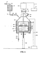
- FIG. 2 A cross-sectional view of the apparatus used to carry out the tests is shown in Figure 2.
- the apparatus comprised a vessel (50) equipped with a stirring means (52), air release means (92) connected to a valve (94), a core sample (54) which was secured to the vessel (50) by means of a holder (56) and a bolt (96) which was secured to rod (97).
- the apparatus was heated by means of heating element (60) which was connected to heat controller (58) by means of line (99).
- a thermocouple (62) connected to the heat controller (58) by means of line (98) regulated the heat of the vessel (50).
- the stirring apparatus (52) was rotated by means of an electric motor (64) and the motor (64) was connected to the rate controller means (72) by means of line (71).
- the shaft (66) of the electric motor (64) was secured to the shaft of stirring apparatus (68) by means of a holder (70).
- the speed of the motor (64) was varied by means of rate controller means (72).
- the drilling fluid to be tested was stored in reservoir (74) which was pressurized through pressure line (76) which was connected to a shut off valve (77).
- the drilling mud in the reservoir (74) was introduced into vessel (50) by means of line (78) which contained a shut-off valve (80).
- the tests were carried out by adding the drilling mud to be tested through line (78) into the vessel (50).
- the drilling fluid was displaced from the vessel (50) during the tests at a rate of 100 ml of drilling fluid per 10 ml of filtrate collected in the graduated cylinder (84).
Landscapes
- Engineering & Computer Science (AREA)
- Chemical & Material Sciences (AREA)
- Life Sciences & Earth Sciences (AREA)
- Geology (AREA)
- General Life Sciences & Earth Sciences (AREA)
- Mining & Mineral Resources (AREA)
- Environmental & Geological Engineering (AREA)
- Fluid Mechanics (AREA)
- Physics & Mathematics (AREA)
- Geochemistry & Mineralogy (AREA)
- Mechanical Engineering (AREA)
- Oil, Petroleum & Natural Gas (AREA)
- Materials Engineering (AREA)
- Organic Chemistry (AREA)
- Earth Drilling (AREA)
- Lubricants (AREA)
Claims (9)
Applications Claiming Priority (2)
| Application Number | Priority Date | Filing Date | Title |
|---|---|---|---|
| US528326 | 1983-08-31 | ||
| US06/528,326 US4525285A (en) | 1983-08-31 | 1983-08-31 | Method of preventing loss of an oil-base drilling fluid during the drilling of an oil or gas well into a subterranean formation |
Publications (3)
| Publication Number | Publication Date |
|---|---|
| EP0137683A2 EP0137683A2 (de) | 1985-04-17 |
| EP0137683A3 EP0137683A3 (en) | 1986-01-02 |
| EP0137683B1 true EP0137683B1 (de) | 1989-03-01 |
Family
ID=24105217
Family Applications (1)
| Application Number | Title | Priority Date | Filing Date |
|---|---|---|---|
| EP84305788A Expired EP0137683B1 (de) | 1983-08-31 | 1984-08-23 | Verhinderung der Bohrflüssigkeitsverluste in unterirdischen Formationen |
Country Status (6)
| Country | Link |
|---|---|
| US (1) | US4525285A (de) |
| EP (1) | EP0137683B1 (de) |
| AU (1) | AU559755B2 (de) |
| CA (1) | CA1217322A (de) |
| DE (1) | DE3476906D1 (de) |
| NO (1) | NO843250L (de) |
Cited By (2)
| Publication number | Priority date | Publication date | Assignee | Title |
|---|---|---|---|---|
| CN102618227A (zh) * | 2012-03-08 | 2012-08-01 | 陕西延长石油(集团)有限责任公司研究院 | 一种陆相页岩气水平井使用的油基钻井液体系 |
| CN103013465A (zh) * | 2012-12-27 | 2013-04-03 | 中国石油集团渤海钻探工程有限公司 | 一种多羟基结构乳化剂及含有该乳化剂的油基钻井液 |
Families Citing this family (27)
| Publication number | Priority date | Publication date | Assignee | Title |
|---|---|---|---|---|
| US4876017A (en) * | 1988-01-19 | 1989-10-24 | Trahan David O | Use of polyalphalolefin in downhole drilling |
| US5045219A (en) * | 1988-01-19 | 1991-09-03 | Coastal Mud, Incorporated | Use of polyalphalolefin in downhole drilling |
| US5189012A (en) * | 1990-03-30 | 1993-02-23 | M-I Drilling Fluids Company | Oil based synthetic hydrocarbon drilling fluid |
| US5498596A (en) * | 1993-09-29 | 1996-03-12 | Mobil Oil Corporation | Non toxic, biodegradable well fluids |
| US6194361B1 (en) | 1998-05-14 | 2001-02-27 | Larry W. Gatlin | Lubricant composition |
| DE19915090A1 (de) * | 1999-04-01 | 2000-10-05 | Mi Drilling Fluids Deutschland | Bohrspülmittel für den Bereich des Tunnelbohrens |
| US7186673B2 (en) * | 2000-04-25 | 2007-03-06 | Exxonmobil Upstream Research Company | Stability enhanced water-in-oil emulsion and method for using same |
| US6419017B1 (en) * | 2000-09-20 | 2002-07-16 | Bj Services Company | Method of preventing gas breakthrough in an oil bearing formation |
| CA2470440A1 (en) * | 2001-12-17 | 2003-07-17 | Exxonmobil Upstream Research Company | Solids-stabilized oil-in-water emulsion and a method for preparing same |
| US7338924B2 (en) | 2002-05-02 | 2008-03-04 | Exxonmobil Upstream Research Company | Oil-in-water-in-oil emulsion |
| US7786049B2 (en) * | 2003-04-10 | 2010-08-31 | Halliburton Energy Services, Inc. | Drilling fluids with improved shale inhibition and methods of drilling in subterranean formations |
| GB2406863A (en) * | 2003-10-09 | 2005-04-13 | Schlumberger Holdings | A well bore treatment fluid for selectively reducing water production |
| US8273689B2 (en) * | 2004-03-03 | 2012-09-25 | Baker Hughes Incorporated | Method for lubricating and/or reducing corrosion of drilling equipment |
| US7311158B2 (en) * | 2004-12-30 | 2007-12-25 | Halliburton Energy Services, Inc. | Silicate-containing additives for well bore treatments and associated methods |
| US20060148656A1 (en) * | 2004-12-30 | 2006-07-06 | Halliburton Energy Services, Inc. | Silicate-containing additives for well bore treatments and associated methods |
| US7943555B2 (en) * | 2005-04-19 | 2011-05-17 | Halliburton Energy Services Inc. | Wellbore treatment kits for forming a polymeric precipitate to reduce the loss of fluid to a subterranean formation |
| US7905287B2 (en) * | 2005-04-19 | 2011-03-15 | Halliburton Energy Services Inc. | Methods of using a polymeric precipitate to reduce the loss of fluid to a subterranean formation |
| US8455404B2 (en) * | 2005-07-15 | 2013-06-04 | Halliburton Energy Services, Inc. | Treatment fluids with improved shale inhibition and methods of use in subterranean operations |
| US7833945B2 (en) * | 2005-07-15 | 2010-11-16 | Halliburton Energy Services Inc. | Treatment fluids with improved shale inhibition and methods of use in subterranean operations |
| CA2632526C (en) | 2005-12-22 | 2014-03-11 | Exxonmobil Upstream Research Company | Method of oil recovery using a foamy oil-external emulsion |
| WO2008024147A1 (en) * | 2006-08-23 | 2008-02-28 | Exxonmobil Upstream Research Company | Composition and method for using waxy oil-external emulsions to modify reservoir permeability profiles |
| US8815785B2 (en) * | 2006-12-29 | 2014-08-26 | Halliburton Energy Services, Inc. | Utilization of surfactant as conformance materials |
| US8889599B1 (en) * | 2013-05-20 | 2014-11-18 | Halliburton Energy Services, Inc. | Methods for use of oil-soluble weighting agents in subterranean formation treatment fluids |
| US9657214B2 (en) * | 2014-07-22 | 2017-05-23 | King Fahd University Of Petroleum And Minerals | Zero-invasion acidic drilling fluid |
| WO2018144067A1 (en) * | 2017-02-03 | 2018-08-09 | Saudi Arabian Oil Company | Oil-based fluid compositions for hydrocarbon recovery applications |
| US11499086B1 (en) * | 2021-12-20 | 2022-11-15 | Halliburton Energy Services, Inc. | Subterranean drilling and completion in geothermal wells |
| US12559667B2 (en) | 2024-02-19 | 2026-02-24 | Schlumberger Technology Corporation | Wellbore fluids including fluid loss materials comprising a polymer and a bridging material and related methods |
Family Cites Families (37)
| Publication number | Priority date | Publication date | Assignee | Title |
|---|---|---|---|---|
| US3125517A (en) * | 1964-03-17 | Chzchzoh | ||
| US2024119A (en) * | 1934-08-11 | 1935-12-10 | Texas Co | Treating oil wells |
| US2079431A (en) * | 1934-10-17 | 1937-05-04 | Standard Oil Dev Co | Plugging water sands by a soap precipitate |
| US2090626A (en) * | 1936-09-05 | 1937-08-24 | Dow Chemical Co | Method of preventing infiltration in wells |
| US2208766A (en) * | 1939-01-16 | 1940-07-23 | Shell Dev | Method of sealing off porous formations |
| US2302913A (en) * | 1939-08-31 | 1942-11-24 | James W Rebbeck | Method of stopping leaks |
| US2297660A (en) * | 1939-11-16 | 1942-09-29 | Shell Dev | Nonaqueous drilling fluid |
| US2497398A (en) * | 1947-05-24 | 1950-02-14 | Shell Dev | Oil base drilling fluid |
| US2623015A (en) * | 1950-10-16 | 1952-12-23 | Union Oil Co | Oil base drilling fluids |
| US2675353A (en) * | 1950-10-20 | 1954-04-13 | Shell Dev | Oil base drilling fluid |
| US3017349A (en) * | 1954-01-08 | 1962-01-16 | Union Oil Co | Drilling fluids |
| US2786530A (en) * | 1955-03-11 | 1957-03-26 | Union Oil Co | Well plugging process |
| US2995514A (en) * | 1957-04-29 | 1961-08-08 | Nat Lead Co | Oil base drilling fluids |
| US2999063A (en) * | 1957-08-13 | 1961-09-05 | Raymond W Hoeppel | Water-in-oil emulsion drilling and fracturing fluid |
| US3085976A (en) * | 1959-06-08 | 1963-04-16 | Continental Oil Co | Oil base drilling mud additive |
| US3141501A (en) * | 1960-08-26 | 1964-07-21 | Pure Oil Co | Control of permeability during water flooding |
| US3175611A (en) * | 1962-12-18 | 1965-03-30 | Halliburton Co | Method of consolidating incompetent sands in oil bearing formation |
| US3318380A (en) * | 1963-08-26 | 1967-05-09 | Shell Oil Co | Method of forming fluid-confined underground storage reservoirs |
| US3435899A (en) * | 1967-04-24 | 1969-04-01 | Halliburton Co | Delayed gelling of sodium silicate and use therefor |
| US3639233A (en) * | 1969-03-18 | 1972-02-01 | Dresser Ind | Well drilling |
| US3656550A (en) * | 1970-09-08 | 1972-04-18 | Amoco Prod Co | Forming a barrier between zones in waterflooding |
| US3658131A (en) * | 1970-10-30 | 1972-04-25 | Cities Service Oil Co | Selective plugging method |
| US3701384A (en) * | 1971-03-11 | 1972-10-31 | Dow Chemical Co | Method and composition for controlling flow through subterranean formations |
| US3729052A (en) * | 1971-06-15 | 1973-04-24 | L Caldwell | Hydrothermal treatment of subsurface earth formations |
| US3866685A (en) * | 1972-07-10 | 1975-02-18 | Getty Oil Co | Methods for selective plugging |
| US3866684A (en) * | 1972-07-10 | 1975-02-18 | Getty Oil Co | Methods for selective plugging |
| US3865189A (en) * | 1972-07-10 | 1975-02-11 | Getty Oil Co | Methods for selective plugging |
| US3882938A (en) * | 1972-07-17 | 1975-05-13 | Union Oil Co | Process for recovering oil from heterogeneous reservoirs |
| US3876007A (en) * | 1974-04-01 | 1975-04-08 | Texaco Inc | Acidization process |
| US4004639A (en) * | 1976-03-17 | 1977-01-25 | Union Oil Company Of California | Selectively plugging the more permeable strata of a subterranean formation |
| US4081029A (en) * | 1976-05-24 | 1978-03-28 | Union Oil Company Of California | Enhanced oil recovery using alkaline sodium silicate solutions |
| US4069869A (en) * | 1977-02-11 | 1978-01-24 | Union Oil Company Of California | Plugging high permeability zones of reservoirs having heterogeneous permeability |
| US4233162A (en) * | 1978-02-07 | 1980-11-11 | Halliburton Company | Oil well fluids and dispersants |
| US4140183A (en) * | 1978-02-13 | 1979-02-20 | Union Oil Company Of California | Micellar flooding process for heterogeneous reservoirs |
| US4296811A (en) * | 1978-07-06 | 1981-10-27 | Phillips Petroleum Company | Method for permeability correction by in situ genesis of macroemulsions in hard brine |
| US4257483A (en) * | 1979-01-11 | 1981-03-24 | The Dow Chemical Company | Method of well completion with casing gel |
| US4301867A (en) * | 1980-06-30 | 1981-11-24 | Marathon Oil Company | Process for selectively reducing the permeability of a subterranean sandstone formation |
-
1983
- 1983-08-31 US US06/528,326 patent/US4525285A/en not_active Expired - Fee Related
-
1984
- 1984-07-18 CA CA000459138A patent/CA1217322A/en not_active Expired
- 1984-07-18 AU AU30811/84A patent/AU559755B2/en not_active Ceased
- 1984-08-15 NO NO843250A patent/NO843250L/no unknown
- 1984-08-23 EP EP84305788A patent/EP0137683B1/de not_active Expired
- 1984-08-23 DE DE8484305788T patent/DE3476906D1/de not_active Expired
Cited By (2)
| Publication number | Priority date | Publication date | Assignee | Title |
|---|---|---|---|---|
| CN102618227A (zh) * | 2012-03-08 | 2012-08-01 | 陕西延长石油(集团)有限责任公司研究院 | 一种陆相页岩气水平井使用的油基钻井液体系 |
| CN103013465A (zh) * | 2012-12-27 | 2013-04-03 | 中国石油集团渤海钻探工程有限公司 | 一种多羟基结构乳化剂及含有该乳化剂的油基钻井液 |
Also Published As
| Publication number | Publication date |
|---|---|
| EP0137683A3 (en) | 1986-01-02 |
| CA1217322A (en) | 1987-02-03 |
| US4525285A (en) | 1985-06-25 |
| AU559755B2 (en) | 1987-03-19 |
| DE3476906D1 (en) | 1989-04-06 |
| AU3081184A (en) | 1985-03-07 |
| EP0137683A2 (de) | 1985-04-17 |
| NO843250L (no) | 1985-03-01 |
Similar Documents
| Publication | Publication Date | Title |
|---|---|---|
| EP0137683B1 (de) | Verhinderung der Bohrflüssigkeitsverluste in unterirdischen Formationen | |
| US4304677A (en) | Method of servicing wellbores | |
| EP0108546B1 (de) | Bohrflüssigkeiten auf Ölbasis | |
| CA2889523C (en) | Wellbore servicing compositions and methods of making and using same | |
| MX2012011102A (es) | Fluidos de perforacion de emulsion invertidos y metodos para perforacion de agujeros. | |
| RU2072383C1 (ru) | Водосмачивающаяся добавка для бурового раствора, способ ее получения и способ бурения скважины | |
| EA029452B1 (ru) | Бессолевые инвертные эмульсионные буровые растворы и способы бурения стволов скважин | |
| US2806531A (en) | Composition for treating wells and method for using same | |
| KR20200107922A (ko) | 유동성 개질제로서 층상 이중 하이드록사이드를 포함하는 오일계 시추액 조성물 | |
| US20200385626A1 (en) | Invert-emulsion oil based mud formulation using calcium salt of fatty acid as primary emulsifier | |
| EP2994516B1 (de) | Zusatzstoffe für auf öl basierende bohrflüssigkeiten | |
| KR20200108405A (ko) | 오일계 시추액을 위한 층상 이중 하이드록사이드 | |
| US10947434B2 (en) | Additive to enhance sag stability of drilling fluid | |
| CA2859236C (en) | Wellbore servicing compositions and methods of making and using same | |
| US3724565A (en) | Method of controlling lost circulation | |
| WO2020101683A1 (en) | Defoaming composition comprising a tall-oil-derived surfactant | |
| WO2020106273A1 (en) | Oil-based drill-in fluid with enhanced fluid loss properties | |
| CN112063375A (zh) | 一种抗高温高密度油基完井液及其制备方法 | |
| EP1786882A1 (de) | Zusammensetzungen und verfahren zur wassereinschränkung und verfestigung unkonsolidierter formationen | |
| US2799646A (en) | External water phase drilling emulsions and additives therefor | |
| US11760920B1 (en) | Lubricant for monovalent and divalent brines | |
| US20230383164A1 (en) | Methods of making and using a lubricant composition | |
| Simpson et al. | The new look in oil-mud technology | |
| US4490262A (en) | Method of servicing wellbores | |
| US12037534B2 (en) | Reclaimed carbon black drilling fluid additive |
Legal Events
| Date | Code | Title | Description |
|---|---|---|---|
| PUAI | Public reference made under article 153(3) epc to a published international application that has entered the european phase |
Free format text: ORIGINAL CODE: 0009012 |
|
| AK | Designated contracting states |
Designated state(s): BE DE FR GB IT NL SE |
|
| PUAL | Search report despatched |
Free format text: ORIGINAL CODE: 0009013 |
|
| AK | Designated contracting states |
Designated state(s): BE DE FR GB IT NL SE |
|
| 17P | Request for examination filed |
Effective date: 19860313 |
|
| 17Q | First examination report despatched |
Effective date: 19880229 |
|
| RAP1 | Party data changed (applicant data changed or rights of an application transferred) |
Owner name: HALLIBURTON COMPANY AND DRESSER INDUSTRIES INC., T |
|
| GRAA | (expected) grant |
Free format text: ORIGINAL CODE: 0009210 |
|
| AK | Designated contracting states |
Kind code of ref document: B1 Designated state(s): BE DE FR GB IT NL SE |
|
| PG25 | Lapsed in a contracting state [announced via postgrant information from national office to epo] |
Ref country code: SE Effective date: 19890301 Ref country code: NL Effective date: 19890301 Ref country code: IT Free format text: LAPSE BECAUSE OF FAILURE TO SUBMIT A TRANSLATION OF THE DESCRIPTION OR TO PAY THE FEE WITHIN THE PRESCRIBED TIME-LIMIT;WARNING: LAPSES OF ITALIAN PATENTS WITH EFFECTIVE DATE BEFORE 2007 MAY HAVE OCCURRED AT ANY TIME BEFORE 2007. THE CORRECT EFFECTIVE DATE MAY BE DIFFERENT FROM THE ONE RECORDED. Effective date: 19890301 Ref country code: FR Free format text: THE PATENT HAS BEEN ANNULLED BY A DECISION OF A NATIONAL AUTHORITY Effective date: 19890301 Ref country code: BE Effective date: 19890301 |
|
| REF | Corresponds to: |
Ref document number: 3476906 Country of ref document: DE Date of ref document: 19890406 |
|
| EN | Fr: translation not filed | ||
| NLV1 | Nl: lapsed or annulled due to failure to fulfill the requirements of art. 29p and 29m of the patents act | ||
| PLBE | No opposition filed within time limit |
Free format text: ORIGINAL CODE: 0009261 |
|
| STAA | Information on the status of an ep patent application or granted ep patent |
Free format text: STATUS: NO OPPOSITION FILED WITHIN TIME LIMIT |
|
| 26N | No opposition filed | ||
| PG25 | Lapsed in a contracting state [announced via postgrant information from national office to epo] |
Ref country code: DE Effective date: 19900501 |
|
| PGFP | Annual fee paid to national office [announced via postgrant information from national office to epo] |
Ref country code: GB Payment date: 19900813 Year of fee payment: 7 |
|
| PG25 | Lapsed in a contracting state [announced via postgrant information from national office to epo] |
Ref country code: GB Effective date: 19910823 |
|
| GBPC | Gb: european patent ceased through non-payment of renewal fee |