EP0137607A1 - Electrically supplying intermittent loads - Google Patents
Electrically supplying intermittent loads Download PDFInfo
- Publication number
- EP0137607A1 EP0137607A1 EP84305157A EP84305157A EP0137607A1 EP 0137607 A1 EP0137607 A1 EP 0137607A1 EP 84305157 A EP84305157 A EP 84305157A EP 84305157 A EP84305157 A EP 84305157A EP 0137607 A1 EP0137607 A1 EP 0137607A1
- Authority
- EP
- European Patent Office
- Prior art keywords
- machine
- arrangement according
- load
- supply
- power
- Prior art date
- Legal status (The legal status is an assumption and is not a legal conclusion. Google has not performed a legal analysis and makes no representation as to the accuracy of the status listed.)
- Withdrawn
Links
Images
Classifications
-
- H—ELECTRICITY
- H02—GENERATION; CONVERSION OR DISTRIBUTION OF ELECTRIC POWER
- H02J—CIRCUIT ARRANGEMENTS OR SYSTEMS FOR SUPPLYING OR DISTRIBUTING ELECTRIC POWER; SYSTEMS FOR STORING ELECTRIC ENERGY
- H02J1/00—Circuit arrangements for dc mains or dc distribution networks
- H02J1/14—Balancing the load in a network
- H02J1/16—Balancing the load in a network using dynamo-electric machines coupled to flywheels
-
- Y—GENERAL TAGGING OF NEW TECHNOLOGICAL DEVELOPMENTS; GENERAL TAGGING OF CROSS-SECTIONAL TECHNOLOGIES SPANNING OVER SEVERAL SECTIONS OF THE IPC; TECHNICAL SUBJECTS COVERED BY FORMER USPC CROSS-REFERENCE ART COLLECTIONS [XRACs] AND DIGESTS
- Y02—TECHNOLOGIES OR APPLICATIONS FOR MITIGATION OR ADAPTATION AGAINST CLIMATE CHANGE
- Y02E—REDUCTION OF GREENHOUSE GAS [GHG] EMISSIONS, RELATED TO ENERGY GENERATION, TRANSMISSION OR DISTRIBUTION
- Y02E60/00—Enabling technologies; Technologies with a potential or indirect contribution to GHG emissions mitigation
- Y02E60/16—Mechanical energy storage, e.g. flywheels or pressurised fluids
Definitions
- This invention relates to electrically supplying intermittent loads.
- Capacitor banks are used to supply intermittent loads such as servomotors, X-ray machines and plasma arcs, but since the capacity required is of the order of 1 Farad, they are necessarily very bulky and expensive.
- the present invention provides a more compact and less expensive arrangement.
- the invention comprises an arrangement for electrically supplying intermittent loads with high peak power comprising a rotating DC machine with a flywheel effect arranged in parallel to a supply so that during periods of no or low demand from the load, the DC machine stores rotary energy, and during peak demand periods the rotary energy is converted into electrical energy which is supplied to the load.
- the arrangement may advantageously be such that the DC machine is capable of delivering peaks of power to the load but absorbs power from the supply at a low rate.
- Control means may be provided controlling the rate at which the DC machine absorbs power from the supply.
- Said control means may comprise a DC-DC converter or an AC-DC converter.
- the arrangement may comprise a smoothing capacitor in parallel with the load, and may comprise a series inductance shunt capacitor filter.
- the armature resistance of the DC machine is preferably low so that the regulation of the DC machine is substantially better than that of the supply.
- the drawings illustrate arrangements for electrically supplying intermittent loads 11 with high peak power comprising a rotary DC machine 12 with a flywheel effect arranged in parallel to a supply 13 so that during periods of no or low demand from the load, the DC machine 12 stores rotary energy, and during peak demand periods the rotary energy is converted into electrical energy which is supplied to the load.
- the load in Figure 1 is a servo motor 11 typically a 100 Volt, 500 Amp machine supplied from a three phase supply 13 through a recitifier 14.
- a pulse width modulated controller 15 controls the servo motor, which requires high peak power for relatively short intervals as shown in Figure lA, which shows velocity U, position X, and power P plotted against time.
- Time t 1 during which the servo is accelerating from rest is typically 0.25 seconds and the power demand during this period is 50KW. Having got up to speed, the power requirement during the constant speed part of the motion is only enough to overcome frictional forces - the time t 2 for this part of the motion is typically 1 second.
- the deceleration period t 3 is typically 0.2 seconds. During this period, the load has a negative power requirement.
- the peak power requirement of 50KW would cause the voltage of the three phase supply normally available to droop significantly, impairing the performance of the servo.
- peak demand is supplied from a DC machine 12 having a flywheel.
- the DC machine 12 is supplied through a DC-DC converter 17 taking its power from the rectifier 14.
- a diode 18 allows the machine 12 to supply power to the system directly.
- a field winding 19 is also energised by the arrangement, but the machine 15 could equally be a permanent magnet machine.
- a smoothing capacitor 29 is placed across the load.
- a flywheel having a moment of inertia of 0.15 Kgm 2 rotating at 6000 rpm can deliver 50KW for 0.25 seconds with a drop in revolutions to 5000 rpm.
- the negative power requirement of the servo can be used to drive the flywheel back up to speed, though losses are inevitable and will have to be made up from the supply. If there is - as would be typical - a four second interval before the next peak demand for another movement of the servo, the flywheel will have ample time to accelerate back to 6000 rpm without causing the supply voltage to droop unacceptably.
- Figure 2 shows an arrangement for supplying peak power requirements to an X-ray generator 11.
- the source this time is a single phase supply 13.
- the X-ray generator 11 has a typical duty cycle as shown in Figure 2A where it consumes in a 100 millisecond pulse with a 10 second cycle time.
- a flywheel having a moment of inertia of 0.25 Kg m 2 running at 7000 rpm would drop to 6740 rpm during the power pulse.
- the circuit includes a series inductance shunt capacitor filter.
- FIG 3 illustrates an arrangement where the load 11 is a plasma arc controlled by a pulse width modulated controller 15. Again, the supply is single phase, rectified. A DC to DC converter 17 is shown supplying run-up power to the DC machine 12, although this is optional if the machine 12 is matched to the rectifier 14. If the plasma arc is not required to cycle, but merely to operate on demand, the switch 21 is included to initiate running up the flywheel. Typically, a plasma arc operates at 100 Volts, 500 Amps.
Abstract
Intermittent electrical loads (11) are supplied with high peak power from a rotating DC machine (12) with a flywheel effect arranged in parallel to a supply (13) so that during periods of no or low demand from the load the DC machine (12) stores rotary energy and during peakk demand periods the rotary energy is converted into electrical energy which is supplied to the load.
Description
- This invention relates to electrically supplying intermittent loads.
- Problems arise when intermittent loads with high peak power demands but relatively low mean power requirements are to be supplied from a source which is not stiff enough to give the peak power without a large voltage drop. Capacitor banks are used to supply intermittent loads such as servomotors, X-ray machines and plasma arcs, but since the capacity required is of the order of 1 Farad, they are necessarily very bulky and expensive.
- The present invention provides a more compact and less expensive arrangement.
- The invention comprises an arrangement for electrically supplying intermittent loads with high peak power comprising a rotating DC machine with a flywheel effect arranged in parallel to a supply so that during periods of no or low demand from the load, the DC machine stores rotary energy, and during peak demand periods the rotary energy is converted into electrical energy which is supplied to the load.
- The arrangement may advantageously be such that the DC machine is capable of delivering peaks of power to the load but absorbs power from the supply at a low rate.
- Control means may be provided controlling the rate at which the DC machine absorbs power from the supply. Said control means may comprise a DC-DC converter or an AC-DC converter.
- The arrangement may comprise a smoothing capacitor in parallel with the load, and may comprise a series inductance shunt capacitor filter.
- The armature resistance of the DC machine is preferably low so that the regulation of the DC machine is substantially better than that of the supply.
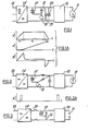
- Embodiments of arrangements according to the invention will now be described with reference to the accompanying drawings in which:
- Figure 1 is a diagram of a velocity or servo position control system,
- Figure 1A is a diagram showing a typical duty cycle for the servo of Figure 1,
- Figure 2 is a diagram of an X-ray generator system,
- Figure 2A is a diagram showing a typical duty cycle for the X-ray generator of Figure 2,
- The drawings illustrate arrangements for electrically supplying
intermittent loads 11 with high peak power comprising arotary DC machine 12 with a flywheel effect arranged in parallel to asupply 13 so that during periods of no or low demand from the load, theDC machine 12 stores rotary energy, and during peak demand periods the rotary energy is converted into electrical energy which is supplied to the load. - The load in Figure 1 is a
servo motor 11 typically a 100 Volt, 500 Amp machine supplied from a threephase supply 13 through arecitifier 14. A pulse width modulatedcontroller 15 controls the servo motor, which requires high peak power for relatively short intervals as shown in Figure lA, which shows velocity U, position X, and power P plotted against time. Time t 1 during which the servo is accelerating from rest is typically 0.25 seconds and the power demand during this period is 50KW. Having got up to speed, the power requirement during the constant speed part of the motion is only enough to overcome frictional forces - the time t2 for this part of the motion is typically 1 second. The deceleration period t3 is typically 0.2 seconds. During this period, the load has a negative power requirement. - The peak power requirement of 50KW would cause the voltage of the three phase supply normally available to droop significantly, impairing the performance of the servo.
- In the arrangement illustrated in Figure 1, peak demand is supplied from a
DC machine 12 having a flywheel. TheDC machine 12 is supplied through a DC-DC converter 17 taking its power from therectifier 14. Adiode 18 allows themachine 12 to supply power to the system directly. As shown, a field winding 19 is also energised by the arrangement, but themachine 15 could equally be a permanent magnet machine. Asmoothing capacitor 29 is placed across the load. - A flywheel having a moment of inertia of 0.15 Kgm2 rotating at 6000 rpm can deliver 50KW for 0.25 seconds with a drop in revolutions to 5000 rpm.
- During time t3, the negative power requirement of the servo can be used to drive the flywheel back up to speed, though losses are inevitable and will have to be made up from the supply. If there is - as would be typical - a four second interval before the next peak demand for another movement of the servo, the flywheel will have ample time to accelerate back to 6000 rpm without causing the supply voltage to droop unacceptably.
- Figure 2 shows an arrangement for supplying peak power requirements to an
X-ray generator 11. The source this time is asingle phase supply 13. TheX-ray generator 11 has a typical duty cycle as shown in Figure 2A where it consumes in a 100 millisecond pulse with a 10 second cycle time. Here, a flywheel having a moment of inertia of 0.25 Kg m2 running at 7000 rpm would drop to 6740 rpm during the power pulse. The circuit includes a series inductance shunt capacitor filter. - Figure 3 illustrates an arrangement where the
load 11 is a plasma arc controlled by a pulse width modulatedcontroller 15. Again, the supply is single phase, rectified. A DC toDC converter 17 is shown supplying run-up power to theDC machine 12, although this is optional if themachine 12 is matched to therectifier 14. If the plasma arc is not required to cycle, but merely to operate on demand, theswitch 21 is included to initiate running up the flywheel. Typically, a plasma arc operates at 100 Volts, 500 Amps. - To supply the peak power requirements of the equipment referred to would require a capacitor bank, if done in the conventional way, having a capacitance of the order of 1 Farad, which occupies a considerable volume, such as could not be accommodated, for example, in a military vehicle for operating a gun.turret, where there is in addition, the problem of the power supp,ly not being stiff enough.
and Figure 3 is a diagram of a plasma arc system.
Claims (12)
1. An arrangement for electrically supplying intermittent loads with high peak power comprising a rotating DC machine with a flywheel effect arranged in parallel to a suply so that during periods of no or low demand from the load, the DC machine stores rotary energy, and during peak demand periods the rotary energy is converted into electrical energy which is supplied to the load.
2. An arrangement according to claim 1, in which the DC machine is capable of delivering peaks of power to the load but absorbs power from the supply at a low rate.
3. An arrangement according to claim 1 or claim 2, comprising control means controlling the rate at which the DC machine absorbs power from the supply.
4. An arrangement according to claim 3, in which said control means comprise a DC-DC converter.
5. An arrangement according to claim 3, in which said control means comprise an AC-DC converter.
6. An arrangement according to any one of claims 1 to 5, comprising a smoothing capacitor in parallel with the load.
7. An arrangement according to any one of claims 1 to 6, comprising a series inductance shunt capacitor filter.
8. An arrangement according to any one of claims 1 to 7, in which the armature resistance of the DC machine is low so that the regulation of the DC machine is substantially better than that of the supply.
9. An arrangement substantially as hereinbefore described with reference to the accompanying drawings.
10. An arrangement according to any one of claims 1 to 10, in which the load comprises a servo system.
11. An arrangement according to any one of claims 1 to 10, in which the load comprises an X-ray machine.
12. An arrangement according to any one of claims 1 to 10, in which the load comprises a plasma arc.
Applications Claiming Priority (2)
| Application Number | Priority Date | Filing Date | Title |
|---|---|---|---|
| GB8320598 | 1983-07-30 | ||
| GB8320598 | 1983-07-30 |
Publications (1)
| Publication Number | Publication Date |
|---|---|
| EP0137607A1 true EP0137607A1 (en) | 1985-04-17 |
Family
ID=10546552
Family Applications (1)
| Application Number | Title | Priority Date | Filing Date |
|---|---|---|---|
| EP84305157A Withdrawn EP0137607A1 (en) | 1983-07-30 | 1984-07-30 | Electrically supplying intermittent loads |
Country Status (1)
| Country | Link |
|---|---|
| EP (1) | EP0137607A1 (en) |
Cited By (8)
| Publication number | Priority date | Publication date | Assignee | Title |
|---|---|---|---|---|
| FR2629961A1 (en) * | 1988-04-11 | 1989-10-13 | Acutronic France Sa | DEVICE FOR DRIVING ROTATION OF A CENTRIFUGAL ARM AND METHOD FOR SUPPLYING POWER TO SUCH A DEVICE |
| EP0363416B1 (en) * | 1987-05-21 | 1993-12-01 | Black & Decker Inc. | Power system for supplying power to a motor |
| US6914342B1 (en) * | 2004-02-06 | 2005-07-05 | Bombardier Recreational Products Inc. | Engine control unit enablement system |
| WO2008017983A2 (en) * | 2006-08-10 | 2008-02-14 | Philips Intellectual Property & Standards Gmbh | Fly wheel electrode of an x-ray tube |
| DE102009024373A1 (en) * | 2009-06-09 | 2010-12-16 | Audi Ag | Flywheel energy storage for main power supply of motor vehicle, comprises rotatably mounted flywheel, where two electrical ports are provided, and additional connection is branched off from one port |
| DE102009024376A1 (en) * | 2009-06-09 | 2010-12-16 | Audi Ag | Main power supply for motor vehicle, has primary system with generator for generating primary voltage, where secondary system is equipped with high power load and energy storage |
| ITCS20110001A1 (en) * | 2011-01-17 | 2012-07-18 | Valentini Valentino | ELECTROMECHANICAL DEVICE FOR CONVERSION EQUIPMENT OF THE MECHANICAL ENERGY OF THE MARINE WAVES IN CURRENT DC STABILIZED BY ELECTRO-MECHANICAL FLYWHEEL. |
| DE102015225146A1 (en) * | 2015-12-14 | 2017-06-14 | Continental Teves Ag & Co. Ohg | Method for compensation of voltage dips in a power supply system and system for power supply |
Citations (4)
| Publication number | Priority date | Publication date | Assignee | Title |
|---|---|---|---|---|
| JPS53118723A (en) * | 1977-03-25 | 1978-10-17 | Toshiba Corp | Flywheel generator |
| JPS54150642A (en) * | 1978-05-18 | 1979-11-27 | Toshiba Corp | Energy storage system |
| FR2481855A1 (en) * | 1980-05-05 | 1981-11-06 | Grady John | RADIOGRAPHY APPARATUS |
| DE8203293U1 (en) * | 1982-02-08 | 1983-07-07 | Siemens AG, 1000 Berlin und 8000 München | Arrangement for energy storage by means of a rotating mass |
-
1984
- 1984-07-30 EP EP84305157A patent/EP0137607A1/en not_active Withdrawn
Patent Citations (4)
| Publication number | Priority date | Publication date | Assignee | Title |
|---|---|---|---|---|
| JPS53118723A (en) * | 1977-03-25 | 1978-10-17 | Toshiba Corp | Flywheel generator |
| JPS54150642A (en) * | 1978-05-18 | 1979-11-27 | Toshiba Corp | Energy storage system |
| FR2481855A1 (en) * | 1980-05-05 | 1981-11-06 | Grady John | RADIOGRAPHY APPARATUS |
| DE8203293U1 (en) * | 1982-02-08 | 1983-07-07 | Siemens AG, 1000 Berlin und 8000 München | Arrangement for energy storage by means of a rotating mass |
Non-Patent Citations (3)
| Title |
|---|
| MESURES, REGULATION, AUTOMATISME, vol. 45, no. 2, February 1980, Paris, France; "Le stockage d'énergie par accumulateurs cinétiques grâce aux paliers magnétiques", pages 77, 79 * |
| PATENT ABSTRACTS OF JAPAN, vol. 2, no. 150, 15th December 1978, page 9599 E78; & JP-A-53-118723 (TOKYO SHIBAURA DENKI K.K.) 17-10-1978 * |
| PATENT ABSTRACTS OF JAPAN, vol. 4, no. 10, 25th January 1980, page 103 E167; & JP-A-54-150642 (TOKYOSHIBAURA DENKI K.K.) 27-11-1979 * |
Cited By (13)
| Publication number | Priority date | Publication date | Assignee | Title |
|---|---|---|---|---|
| EP0363416B1 (en) * | 1987-05-21 | 1993-12-01 | Black & Decker Inc. | Power system for supplying power to a motor |
| FR2629961A1 (en) * | 1988-04-11 | 1989-10-13 | Acutronic France Sa | DEVICE FOR DRIVING ROTATION OF A CENTRIFUGAL ARM AND METHOD FOR SUPPLYING POWER TO SUCH A DEVICE |
| EP0337863A1 (en) * | 1988-04-11 | 1989-10-18 | Acutronic-France S.A. | Rotation drive device for a centrifugal arm and power supply method for such a device |
| US4920303A (en) * | 1988-04-11 | 1990-04-24 | Acutronic France | Device for rotary-driving a centrifuge arm and method for power-feeding said device |
| US6914342B1 (en) * | 2004-02-06 | 2005-07-05 | Bombardier Recreational Products Inc. | Engine control unit enablement system |
| WO2008017983A3 (en) * | 2006-08-10 | 2008-04-10 | Philips Intellectual Property | Fly wheel electrode of an x-ray tube |
| WO2008017983A2 (en) * | 2006-08-10 | 2008-02-14 | Philips Intellectual Property & Standards Gmbh | Fly wheel electrode of an x-ray tube |
| DE102009024373A1 (en) * | 2009-06-09 | 2010-12-16 | Audi Ag | Flywheel energy storage for main power supply of motor vehicle, comprises rotatably mounted flywheel, where two electrical ports are provided, and additional connection is branched off from one port |
| DE102009024376A1 (en) * | 2009-06-09 | 2010-12-16 | Audi Ag | Main power supply for motor vehicle, has primary system with generator for generating primary voltage, where secondary system is equipped with high power load and energy storage |
| DE102009024373B4 (en) * | 2009-06-09 | 2015-11-12 | Audi Ag | Vehicle electrical system with a flywheel energy storage and method for controlling a process of starting an internal combustion engine |
| DE102009024376B4 (en) * | 2009-06-09 | 2015-12-03 | Audi Ag | On-board network for a motor vehicle, motor vehicle and method for operating a vehicle electrical system |
| ITCS20110001A1 (en) * | 2011-01-17 | 2012-07-18 | Valentini Valentino | ELECTROMECHANICAL DEVICE FOR CONVERSION EQUIPMENT OF THE MECHANICAL ENERGY OF THE MARINE WAVES IN CURRENT DC STABILIZED BY ELECTRO-MECHANICAL FLYWHEEL. |
| DE102015225146A1 (en) * | 2015-12-14 | 2017-06-14 | Continental Teves Ag & Co. Ohg | Method for compensation of voltage dips in a power supply system and system for power supply |
Similar Documents
| Publication | Publication Date | Title |
|---|---|---|
| EP1641110B1 (en) | Motor driving apparatus | |
| EP1039625B1 (en) | Operation of a switched reluctance machine from dual supply voltages | |
| KR101172340B1 (en) | Controller for permanent magnet alternator | |
| US5418401A (en) | Power supply apparatus for a vehicle having batteries of different voltages which are charged according to alternator speed | |
| US4131829A (en) | Electric power converting apparatus for use in battery cars | |
| US5237494A (en) | Frequency inverting apparatus | |
| US3715642A (en) | Dc control circuits for direct drive motors continuously coupled to sewing machines for controlling sewing functions | |
| EP0137607A1 (en) | Electrically supplying intermittent loads | |
| GB1440475A (en) | Static converter | |
| EP0577843A1 (en) | Reluctance motor and rotor of high-speed reluctance motor | |
| US3597672A (en) | Electrical drive systems for sewing machines | |
| JPH08223963A (en) | Circuit device for controlling motor commutated electronically | |
| EP0624834B1 (en) | Single cycle positioning system | |
| US3609495A (en) | Control circuits for electromagnetic clutch-brake driving devices | |
| JP2662296B2 (en) | Motor control device | |
| WO1998016983A1 (en) | Time multiplexing of transformer secondary power windings | |
| EP1368876A1 (en) | Device system for multiple motors | |
| GB2062380A (en) | Regenerative braking systems for D.C. motors | |
| US4161919A (en) | Motor control system for sewing machine | |
| US3699419A (en) | Power thyristor chopper | |
| EP3469698B1 (en) | Method and apparatus for operating an electric motor | |
| KR830001532B1 (en) | AC motor drive control device | |
| JP2720468B2 (en) | Vehicle charge control device | |
| GB2224171A (en) | Operating AC motors | |
| KR950003027Y1 (en) | Inverter circuit |
Legal Events
| Date | Code | Title | Description |
|---|---|---|---|
| PUAI | Public reference made under article 153(3) epc to a published international application that has entered the european phase |
Free format text: ORIGINAL CODE: 0009012 |
|
| AK | Designated contracting states |
Designated state(s): AT BE CH DE FR GB IT LI LU NL SE |
|
| STAA | Information on the status of an ep patent application or granted ep patent |
Free format text: STATUS: THE APPLICATION IS DEEMED TO BE WITHDRAWN |
|
| 18D | Application deemed to be withdrawn |
Effective date: 19851018 |