EP0137244A2 - Structure for connecting overhead earth wires containing optical fiber units - Google Patents
Structure for connecting overhead earth wires containing optical fiber units Download PDFInfo
- Publication number
- EP0137244A2 EP0137244A2 EP84109950A EP84109950A EP0137244A2 EP 0137244 A2 EP0137244 A2 EP 0137244A2 EP 84109950 A EP84109950 A EP 84109950A EP 84109950 A EP84109950 A EP 84109950A EP 0137244 A2 EP0137244 A2 EP 0137244A2
- Authority
- EP
- European Patent Office
- Prior art keywords
- optical fiber
- conductors
- fiber unit
- protecting
- overhead earth
- Prior art date
- Legal status (The legal status is an assumption and is not a legal conclusion. Google has not performed a legal analysis and makes no representation as to the accuracy of the status listed.)
- Granted
Links
Images

Classifications
-
- G—PHYSICS
- G02—OPTICS
- G02B—OPTICAL ELEMENTS, SYSTEMS OR APPARATUS
- G02B6/00—Light guides; Structural details of arrangements comprising light guides and other optical elements, e.g. couplings
- G02B6/44—Mechanical structures for providing tensile strength and external protection for fibres, e.g. optical transmission cables
-
- G—PHYSICS
- G02—OPTICS
- G02B—OPTICAL ELEMENTS, SYSTEMS OR APPARATUS
- G02B6/00—Light guides; Structural details of arrangements comprising light guides and other optical elements, e.g. couplings
- G02B6/24—Coupling light guides
- G02B6/36—Mechanical coupling means
- G02B6/38—Mechanical coupling means having fibre to fibre mating means
- G02B6/3801—Permanent connections, i.e. wherein fibres are kept aligned by mechanical means
-
- G—PHYSICS
- G02—OPTICS
- G02B—OPTICAL ELEMENTS, SYSTEMS OR APPARATUS
- G02B6/00—Light guides; Structural details of arrangements comprising light guides and other optical elements, e.g. couplings
- G02B6/44—Mechanical structures for providing tensile strength and external protection for fibres, e.g. optical transmission cables
- G02B6/4401—Optical cables
- G02B6/4407—Optical cables with internal fluted support member
-
- G—PHYSICS
- G02—OPTICS
- G02B—OPTICAL ELEMENTS, SYSTEMS OR APPARATUS
- G02B6/00—Light guides; Structural details of arrangements comprising light guides and other optical elements, e.g. couplings
- G02B6/44—Mechanical structures for providing tensile strength and external protection for fibres, e.g. optical transmission cables
- G02B6/4401—Optical cables
- G02B6/4415—Cables for special applications
- G02B6/4416—Heterogeneous cables
- G02B6/4422—Heterogeneous cables of the overhead type
-
- G—PHYSICS
- G02—OPTICS
- G02B—OPTICAL ELEMENTS, SYSTEMS OR APPARATUS
- G02B6/00—Light guides; Structural details of arrangements comprising light guides and other optical elements, e.g. couplings
- G02B6/44—Mechanical structures for providing tensile strength and external protection for fibres, e.g. optical transmission cables
- G02B6/4439—Auxiliary devices
- G02B6/4471—Terminating devices ; Cable clamps
-
- G—PHYSICS
- G02—OPTICS
- G02B—OPTICAL ELEMENTS, SYSTEMS OR APPARATUS
- G02B6/00—Light guides; Structural details of arrangements comprising light guides and other optical elements, e.g. couplings
- G02B6/46—Processes or apparatus adapted for installing or repairing optical fibres or optical cables
- G02B6/48—Overhead installation
Abstract
Description
- The present invention relates to improved structure for connecting overhead earth wires containing an optical fiber unit, and more particularly to the structure for connecting them in a dead end clamp or a mid span joint.
- Fig. 1 shows an example of overhead earth wires containing an optical fiber unit. An
optical fiber unit 2 is disposed in the center of a bundle of sixconductors 1, each of which consists of e.g. an Alumoweld wire. - Fig. 2 shows the above-described
overhead earth wire 3 inserted in adead end clamp 4, which is compressed at the portions indicated by arrows a and b for mechanical and electrical connections. - In case of a conventional structure, a wedge-shaped protecting
member 5 is inserted between theconductors 1 and theoptical fiber unit 2 in order to protect the unit from deformation when compressed. The protectingmember 5 is provided at one end thereof with aring 6 having holes into whichpins 7 are inserted at regular intervals between theconductors 1 as shown in Fig. 4 so as to prevent the conductors from shifting at one side. At and near the portion where thepins 7 are inserted, they serve to separate theconductors 1 evenly from one another but do not at a position far away from the portion. In addition, the compression strength is not sufficent in the proximity of the end of the protectingmember 5, because the shifting of theconductors 1 is liable to occur in this area. In order to eliminate this drawback, the area compressed has been enlarged with the use of anelongated member 5, so that required connecting strength will be obtained. The situation was the same in case the wires are connected in a mid span joint instead of a dead end clamp. - As mentioned above, in the conventional structure for connecting the overhead earth wires, work efficiency was unsatisfactory because of use of a long protecting member and necessity of inserting the pins between the conductors.
- An object of the present invention is to provide an improved structure for connecting overhead earth wires containing an optical fiber unit which obviates the abovesaid shortcomings.
- In accordance with the present invention, a protecting member is used which is formed with a through hole for passing an optical fiber unit therethrough and on its outer surface with a plurality of longitudinal grooves to receive the conductors therein.
- Other objects and features of the present invention will become apparent from the following description taken with reference to the accompanying drawings, in which:
- Fig. 1 is a sectional view of an example of an overhead earth wire containing an optical fiber unit;
- Fig. 2 is a longitudinal section of a conventional structure;
- Fig. 3 is an enlarged longitudinal section of a portion thereof;
- Fig. 4 is a sectional view taken along line IV-IV of Fig. 3;
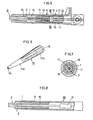
- Fig. 5 is a longitudinal section of a structure embodying the present invention;
- Fig. 6 is a perspective view of the protecting member used in the embodiment;
- Fig. 7 is an enlarged sectional view taken along line VII-VII of Fig. 5: and
- Fig. 8 is a longitudinal section of the structure using a mid span joint.
- Figs. 5 to 7 show a preferred embodiment of the present invention in which a dead end clamp is used. The
dead end clamp 10 comprises amale member 11 in combination with afemale member 12. Thefemale member 12 is provided with ahole 13 in one end thereof through which theoverhead earth wire 3 is drawn thereinto, and with ahole 14 in the other end to receive themale member 11. The male member i ≡ provided with ahole 15 in one end thereof to receire theoverhead earth wire 3, and with athrough hole 16 which communicates with thehole 15. - A protecting
member 17 is inserted into thehole 15 of themale member 11. Theoptical fiber unit 2 is inserted into athrough hole 18 provided in the protectingmember 17, passed through thehole 16 of themale member 11, and crawn out of the dead end clamp. - As shown in Fig. 6, the protecting
member 17 has atapered portion 17a and acylindrical portion 17b continuing from the thick end of the tapered portion, and is formed withlongitudinal grooves 19 to receive theconductors 1 at regular intervals. These grooves extend from the middle of thetapered portion 17a to the opposite end of thecylindrical portion 17b. The depth of eachgroove 19 is slightly smaller than the diameter of eachconductor 1. - The protecting
member 17 is inserted into thehole 15 of themale member 11 so that its grooved portion is housed in thehole 15. Theconductors 1 are inserted from the end of thetapered portion 17a of the protectingmember 17 so as to be evenly distributed by thegrooves 19. - When the parts have been assembled in the above-described manner, i.e., into a condition shown in Fig. 5, compression is applied to the portions indicated by arrows a and b so as to bring the
male member 11,female member 12 andconductors 1 into close contact with each other. Because of the provision of the protectingmember 17, theoptical fiber unit 2 is not affected when compressed. - Fig. 8 shows another embodiment in which the connection is performed in a
mid span joint 20. The same protectingmember 17 as the above-described one are inserted into both ends of thesleeve 20. Then the sleeve is compressed to ensure mechanical and electrical connections. Thenumeral 21 refers to a connector of theoptical fiber units 2. - It will be understood from the foregoing that since the protecting member is formed with equally spaced grooves, it can keep the conductors at equal spacings. Because the conductors cannot shift at one side, the connecting strength by compression of the dead end clamp (or mid span joint) against the conductors will be higher than before. The protecting member do not have to be so long as before.
Claims (4)
Priority Applications (1)
| Application Number | Priority Date | Filing Date | Title |
|---|---|---|---|
| AT84109950T ATE44626T1 (en) | 1983-08-31 | 1984-08-21 | CONNECTION ESTABLISHMENT FOR ABOVE GROUND CABLES THAT CONTAIN OPTICAL FIBERS. |
Applications Claiming Priority (2)
| Application Number | Priority Date | Filing Date | Title |
|---|---|---|---|
| JP58161543A JPS6051808A (en) | 1983-08-31 | 1983-08-31 | Connection part of overhead earth-wire containing optical fiber unit |
| JP161543/83 | 1983-08-31 |
Publications (3)
| Publication Number | Publication Date |
|---|---|
| EP0137244A2 true EP0137244A2 (en) | 1985-04-17 |
| EP0137244A3 EP0137244A3 (en) | 1986-02-05 |
| EP0137244B1 EP0137244B1 (en) | 1989-07-12 |
Family
ID=15737097
Family Applications (1)
| Application Number | Title | Priority Date | Filing Date |
|---|---|---|---|
| EP84109950A Expired EP0137244B1 (en) | 1983-08-31 | 1984-08-21 | Structure for connecting overhead earth wires containing optical fiber units |
Country Status (9)
| Country | Link |
|---|---|
| US (1) | US4610503A (en) |
| EP (1) | EP0137244B1 (en) |
| JP (1) | JPS6051808A (en) |
| KR (1) | KR900001641B1 (en) |
| AT (1) | ATE44626T1 (en) |
| AU (1) | AU562387B2 (en) |
| CA (1) | CA1244692A (en) |
| DE (1) | DE3478965D1 (en) |
| ZA (1) | ZA846708B (en) |
Cited By (7)
| Publication number | Priority date | Publication date | Assignee | Title |
|---|---|---|---|---|
| GB2165958A (en) * | 1984-09-28 | 1986-04-23 | Bicc Plc | Overhead electric and optical transmission connection |
| DE3531693A1 (en) * | 1985-09-05 | 1987-03-12 | Licentia Gmbh | Adapter for adapting optical fibre cables of multifibre design to those having a star structure |
| FR2637803A1 (en) * | 1988-10-19 | 1990-04-20 | Ire Celltarg Sa | ESTROGENIC AND PROGESTAGENIC STEROID HORMONE RECEPTOR SPECIFIC LIGANDS, APPLICATION AND INTERMEDIATE SYNTHESIS PRODUCTS |
| GB2234830A (en) * | 1989-06-14 | 1991-02-13 | Bicc Plc | Overhead optical cable transmission system |
| EP0433565A2 (en) * | 1989-12-21 | 1991-06-26 | Felten & Guilleaume Energietechnik AG | Light wave guide end connection for a light wave guide phase conductor |
| KR20010088554A (en) * | 2001-08-06 | 2001-09-28 | 용근순 | Structure of optical fiber cable within power source cable |
| WO2013139649A1 (en) * | 2012-03-21 | 2013-09-26 | Huber+Suhner Ag | Environmentally sealed cable breakout assemblies |
Families Citing this family (6)
| Publication number | Priority date | Publication date | Assignee | Title |
|---|---|---|---|---|
| GB2128357B (en) * | 1982-10-06 | 1986-05-21 | Standard Telephones Cables Ltd | Optical fibre cables |
| JPS60159404U (en) * | 1984-03-16 | 1985-10-23 | 株式会社フジクラ | Connection structure of optical fiber composite overhead wire |
| FR2601785B1 (en) * | 1986-07-15 | 1989-07-28 | Telecommunications Sa | RESERVE DEVICE FOR FIBER OPTIC CABLE AND METHOD OF IMPLEMENTING SAME |
| IT1199823B (en) * | 1986-12-19 | 1989-01-05 | Ente Naz Energia Elettrica | ELECTRIC LINE WITH BEAM CONDUCTORS EQUIPPED WITH METALLIC OR DIELECTRIC CABLES EMBEDDING OPTICAL FIBERS FOR TELECOMMUNICATION |
| US4799760A (en) * | 1988-02-29 | 1989-01-24 | Siecor Corporation | Strain relief apparatus |
| US4883336A (en) * | 1989-02-17 | 1989-11-28 | Conseil National De Recherches Du Canada | Method and leadthrough system for laying out optical fibres across an aperture of a container shell |
Citations (5)
| Publication number | Priority date | Publication date | Assignee | Title |
|---|---|---|---|---|
| US3883681A (en) * | 1973-12-17 | 1975-05-13 | Us Navy | Anchor assembly for strength member of communication cable |
| DE2725458A1 (en) * | 1976-06-09 | 1977-12-22 | Itt Ind Gmbh Deutsche | LIGHT GUIDE CONNECTOR |
| JPS5774705A (en) * | 1980-10-28 | 1982-05-11 | Nippon Telegr & Teleph Corp <Ntt> | Manufacture of submarine optical-cable anchor |
| JPS5854301A (en) * | 1981-09-28 | 1983-03-31 | Nippon Telegr & Teleph Corp <Ntt> | Anchor part for submarine optical fiber cable |
| EP0131283A2 (en) * | 1983-07-07 | 1985-01-16 | Augat Inc. | Method and apparatus for anchoring optical cables to optical connectors |
Family Cites Families (3)
| Publication number | Priority date | Publication date | Assignee | Title |
|---|---|---|---|---|
| JPS58163905A (en) * | 1982-03-25 | 1983-09-28 | Hitachi Cable Ltd | Optical fiber cable |
| ZW8883A1 (en) * | 1982-04-22 | 1983-07-06 | Bicc Plc | An improved flexible elongate body |
| FR2534700B1 (en) * | 1982-10-19 | 1986-02-14 | Silec Liaisons Elec | DEVICE FOR SEPARATING AND PROTECTING OPTICAL FIBERS FROM AN OPTICAL CABLE |
-
1983
- 1983-08-31 JP JP58161543A patent/JPS6051808A/en active Granted
-
1984
- 1984-08-20 KR KR1019840005006A patent/KR900001641B1/en not_active IP Right Cessation
- 1984-08-20 AU AU32076/84A patent/AU562387B2/en not_active Ceased
- 1984-08-20 US US06/642,526 patent/US4610503A/en not_active Expired - Fee Related
- 1984-08-21 CA CA000461434A patent/CA1244692A/en not_active Expired
- 1984-08-21 EP EP84109950A patent/EP0137244B1/en not_active Expired
- 1984-08-21 AT AT84109950T patent/ATE44626T1/en not_active IP Right Cessation
- 1984-08-21 DE DE8484109950T patent/DE3478965D1/en not_active Expired
- 1984-08-28 ZA ZA846708A patent/ZA846708B/en unknown
Patent Citations (5)
| Publication number | Priority date | Publication date | Assignee | Title |
|---|---|---|---|---|
| US3883681A (en) * | 1973-12-17 | 1975-05-13 | Us Navy | Anchor assembly for strength member of communication cable |
| DE2725458A1 (en) * | 1976-06-09 | 1977-12-22 | Itt Ind Gmbh Deutsche | LIGHT GUIDE CONNECTOR |
| JPS5774705A (en) * | 1980-10-28 | 1982-05-11 | Nippon Telegr & Teleph Corp <Ntt> | Manufacture of submarine optical-cable anchor |
| JPS5854301A (en) * | 1981-09-28 | 1983-03-31 | Nippon Telegr & Teleph Corp <Ntt> | Anchor part for submarine optical fiber cable |
| EP0131283A2 (en) * | 1983-07-07 | 1985-01-16 | Augat Inc. | Method and apparatus for anchoring optical cables to optical connectors |
Non-Patent Citations (2)
| Title |
|---|
| PATENT ABSTRACTS OF JAPAN, vol. 6, no. 156 (P-135)[1034], 17th August 1982; & JP-A-57 074 705 (NIPPON DENSHIN DENWA KOSHA) 11-05-1982 * |
| PATENT ABSTRACTS OF JAPAN, vol. 7, no. 138 (P-204)[1283], 16th June 1983; & JP-A-58 054 301 (NIPPON DENSHIN DENWA KOSHA) 31-03-1983 * |
Cited By (11)
| Publication number | Priority date | Publication date | Assignee | Title |
|---|---|---|---|---|
| GB2165958A (en) * | 1984-09-28 | 1986-04-23 | Bicc Plc | Overhead electric and optical transmission connection |
| US4717237A (en) * | 1984-09-28 | 1988-01-05 | Austin Kenneth A | Overhead electric and optical transmission systems |
| DE3531693A1 (en) * | 1985-09-05 | 1987-03-12 | Licentia Gmbh | Adapter for adapting optical fibre cables of multifibre design to those having a star structure |
| FR2637803A1 (en) * | 1988-10-19 | 1990-04-20 | Ire Celltarg Sa | ESTROGENIC AND PROGESTAGENIC STEROID HORMONE RECEPTOR SPECIFIC LIGANDS, APPLICATION AND INTERMEDIATE SYNTHESIS PRODUCTS |
| GB2234830A (en) * | 1989-06-14 | 1991-02-13 | Bicc Plc | Overhead optical cable transmission system |
| US5018825A (en) * | 1989-06-14 | 1991-05-28 | Bicc Public Limited Company | Overhead optical transmission system |
| EP0433565A2 (en) * | 1989-12-21 | 1991-06-26 | Felten & Guilleaume Energietechnik AG | Light wave guide end connection for a light wave guide phase conductor |
| EP0433565A3 (en) * | 1989-12-21 | 1991-10-23 | Felten & Guilleaume Energietechnik Ag | Light wave guide end connection for a light wave guide phase conductor |
| KR20010088554A (en) * | 2001-08-06 | 2001-09-28 | 용근순 | Structure of optical fiber cable within power source cable |
| WO2013139649A1 (en) * | 2012-03-21 | 2013-09-26 | Huber+Suhner Ag | Environmentally sealed cable breakout assemblies |
| US9548603B2 (en) | 2012-03-21 | 2017-01-17 | Huber+Suhner Ag | Environmentally sealed cable breakout assemblies |
Also Published As
| Publication number | Publication date |
|---|---|
| US4610503A (en) | 1986-09-09 |
| ATE44626T1 (en) | 1989-07-15 |
| KR900001641B1 (en) | 1990-03-17 |
| EP0137244A3 (en) | 1986-02-05 |
| AU3207684A (en) | 1985-03-07 |
| DE3478965D1 (en) | 1989-08-17 |
| JPS6051808A (en) | 1985-03-23 |
| AU562387B2 (en) | 1987-06-11 |
| CA1244692A (en) | 1988-11-15 |
| ZA846708B (en) | 1985-04-24 |
| JPH0568683B2 (en) | 1993-09-29 |
| EP0137244B1 (en) | 1989-07-12 |
| KR850001550A (en) | 1985-03-30 |
Similar Documents
| Publication | Publication Date | Title |
|---|---|---|
| US5989056A (en) | Cable connector with stress relief assembly | |
| EP0260774B1 (en) | Fiber optic connector strain relief | |
| EP0137244A2 (en) | Structure for connecting overhead earth wires containing optical fiber units | |
| US5044719A (en) | Cable connector | |
| US4444449A (en) | Electrical connector | |
| KR890007925Y1 (en) | Plug | |
| KR900017235A (en) | Connector assembly with coding element | |
| MX164754B (en) | CONNECTOR BENCH FOR CABLE WIRES IN PARTICULAR OF TELEPHONE CABLES | |
| US4586768A (en) | Electrical connector plug with an integral ejector | |
| CA2509412A1 (en) | Plug and block connector system for differential contact pairs | |
| KR970707607A (en) | BONDING DISCRETE WIRES FOR FOR UNITARY RIBBON CABLE FOR HIGH PERFORMANCE CONNECTOR | |
| US3504332A (en) | Electrical connector | |
| US4373765A (en) | Plug connection for ribbon cables | |
| US5055065A (en) | Snap | |
| US3054979A (en) | Multiple electrical connector | |
| JPH0458606B2 (en) | ||
| US5520549A (en) | Connector apparatus, housing, and connecting element | |
| GB1535646A (en) | Cross-connection assembly for communications wires | |
| GB2112216A (en) | Electrical connectors for use telecommunications equipment | |
| JP3623142B2 (en) | Electric wire connector | |
| US4607902A (en) | Electric wire connector | |
| JPH0418215Y2 (en) | ||
| US4606593A (en) | Electric wire connector | |
| GB2099240A (en) | Improvements in and relating to flat electrical connector pins | |
| GB2100074A (en) | Wire connector |
Legal Events
| Date | Code | Title | Description |
|---|---|---|---|
| PUAI | Public reference made under article 153(3) epc to a published international application that has entered the european phase |
Free format text: ORIGINAL CODE: 0009012 |
|
| AK | Designated contracting states |
Designated state(s): AT CH DE FR GB IT LI NL SE |
|
| PUAL | Search report despatched |
Free format text: ORIGINAL CODE: 0009013 |
|
| AK | Designated contracting states |
Designated state(s): AT CH DE FR GB IT LI NL SE |
|
| RHK1 | Main classification (correction) |
Ipc: G02B 6/38 |
|
| 17P | Request for examination filed |
Effective date: 19860730 |
|
| 17Q | First examination report despatched |
Effective date: 19871123 |
|
| GRAA | (expected) grant |
Free format text: ORIGINAL CODE: 0009210 |
|
| AK | Designated contracting states |
Kind code of ref document: B1 Designated state(s): AT CH DE FR GB IT LI NL SE |
|
| REF | Corresponds to: |
Ref document number: 44626 Country of ref document: AT Date of ref document: 19890715 Kind code of ref document: T |
|
| REF | Corresponds to: |
Ref document number: 3478965 Country of ref document: DE Date of ref document: 19890817 |
|
| ET | Fr: translation filed | ||
| ITF | It: translation for a ep patent filed |
Owner name: UFFICIO BREVETTI RICCARDI & C. |
|
| PLBE | No opposition filed within time limit |
Free format text: ORIGINAL CODE: 0009261 |
|
| STAA | Information on the status of an ep patent application or granted ep patent |
Free format text: STATUS: NO OPPOSITION FILED WITHIN TIME LIMIT |
|
| 26N | No opposition filed | ||
| ITTA | It: last paid annual fee | ||
| EAL | Se: european patent in force in sweden |
Ref document number: 84109950.0 |
|
| PGFP | Annual fee paid to national office [announced via postgrant information from national office to epo] |
Ref country code: FR Payment date: 19960809 Year of fee payment: 13 |
|
| PGFP | Annual fee paid to national office [announced via postgrant information from national office to epo] |
Ref country code: GB Payment date: 19960812 Year of fee payment: 13 |
|
| PGFP | Annual fee paid to national office [announced via postgrant information from national office to epo] |
Ref country code: AT Payment date: 19960813 Year of fee payment: 13 |
|
| PGFP | Annual fee paid to national office [announced via postgrant information from national office to epo] |
Ref country code: SE Payment date: 19960815 Year of fee payment: 13 |
|
| PGFP | Annual fee paid to national office [announced via postgrant information from national office to epo] |
Ref country code: NL Payment date: 19960828 Year of fee payment: 13 |
|
| PGFP | Annual fee paid to national office [announced via postgrant information from national office to epo] |
Ref country code: DE Payment date: 19960830 Year of fee payment: 13 |
|
| PGFP | Annual fee paid to national office [announced via postgrant information from national office to epo] |
Ref country code: CH Payment date: 19960906 Year of fee payment: 13 |
|
| PG25 | Lapsed in a contracting state [announced via postgrant information from national office to epo] |
Ref country code: GB Free format text: LAPSE BECAUSE OF NON-PAYMENT OF DUE FEES Effective date: 19970821 Ref country code: AT Free format text: LAPSE BECAUSE OF NON-PAYMENT OF DUE FEES Effective date: 19970821 |
|
| PG25 | Lapsed in a contracting state [announced via postgrant information from national office to epo] |
Ref country code: SE Free format text: LAPSE BECAUSE OF NON-PAYMENT OF DUE FEES Effective date: 19970822 |
|
| PG25 | Lapsed in a contracting state [announced via postgrant information from national office to epo] |
Ref country code: LI Free format text: LAPSE BECAUSE OF NON-PAYMENT OF DUE FEES Effective date: 19970831 Ref country code: CH Free format text: LAPSE BECAUSE OF NON-PAYMENT OF DUE FEES Effective date: 19970831 |
|
| PG25 | Lapsed in a contracting state [announced via postgrant information from national office to epo] |
Ref country code: NL Free format text: LAPSE BECAUSE OF NON-PAYMENT OF DUE FEES Effective date: 19980301 |
|
| GBPC | Gb: european patent ceased through non-payment of renewal fee |
Effective date: 19970821 |
|
| REG | Reference to a national code |
Ref country code: CH Ref legal event code: PL |
|
| PG25 | Lapsed in a contracting state [announced via postgrant information from national office to epo] |
Ref country code: FR Free format text: LAPSE BECAUSE OF NON-PAYMENT OF DUE FEES Effective date: 19980430 |
|
| PG25 | Lapsed in a contracting state [announced via postgrant information from national office to epo] |
Ref country code: DE Free format text: LAPSE BECAUSE OF NON-PAYMENT OF DUE FEES Effective date: 19980501 |
|
| EUG | Se: european patent has lapsed |
Ref document number: 84109950.0 |
|
| NLV4 | Nl: lapsed or anulled due to non-payment of the annual fee |
Effective date: 19980301 |
|
| REG | Reference to a national code |
Ref country code: FR Ref legal event code: ST |