EP0137084A2 - Hydrocyclones - Google Patents
Hydrocyclones Download PDFInfo
- Publication number
- EP0137084A2 EP0137084A2 EP83306210A EP83306210A EP0137084A2 EP 0137084 A2 EP0137084 A2 EP 0137084A2 EP 83306210 A EP83306210 A EP 83306210A EP 83306210 A EP83306210 A EP 83306210A EP 0137084 A2 EP0137084 A2 EP 0137084A2
- Authority
- EP
- European Patent Office
- Prior art keywords
- hydrocyclone
- volute
- hydrocyclones
- diameter
- vortex chamber
- Prior art date
- Legal status (The legal status is an assumption and is not a legal conclusion. Google has not performed a legal analysis and makes no representation as to the accuracy of the status listed.)
- Withdrawn
Links
Images
Classifications
-
- B—PERFORMING OPERATIONS; TRANSPORTING
- B04—CENTRIFUGAL APPARATUS OR MACHINES FOR CARRYING-OUT PHYSICAL OR CHEMICAL PROCESSES
- B04C—APPARATUS USING FREE VORTEX FLOW, e.g. CYCLONES
- B04C5/00—Apparatus in which the axial direction of the vortex is reversed
- B04C5/08—Vortex chamber constructions
- B04C5/081—Shapes or dimensions
-
- B—PERFORMING OPERATIONS; TRANSPORTING
- B04—CENTRIFUGAL APPARATUS OR MACHINES FOR CARRYING-OUT PHYSICAL OR CHEMICAL PROCESSES
- B04C—APPARATUS USING FREE VORTEX FLOW, e.g. CYCLONES
- B04C5/00—Apparatus in which the axial direction of the vortex is reversed
-
- B—PERFORMING OPERATIONS; TRANSPORTING
- B04—CENTRIFUGAL APPARATUS OR MACHINES FOR CARRYING-OUT PHYSICAL OR CHEMICAL PROCESSES
- B04C—APPARATUS USING FREE VORTEX FLOW, e.g. CYCLONES
- B04C5/00—Apparatus in which the axial direction of the vortex is reversed
- B04C5/02—Construction of inlets by which the vortex flow is generated, e.g. tangential admission, the fluid flow being forced to follow a downward path by spirally wound bulkheads, or with slightly downwardly-directed tangential admission
Definitions
- This invention relates to small hydrocyclones, having a maximum vortex chamber diameter in the range 7 to 14 mm, and having a feed passage which at its inner end communicates with a channel extending around part of the periphery of the chamber, such channel forming a volute guideway which curves progressively inwardly to merge with the radially symmetrical wall of the vortex chamber.
- he invention also relates to starch recovery processes using such hydrocyclones.
- a hydrocyclone as is well known, comprises a radially symmetrical chamber, herein called “vortex chamber”, which tapers over the whole or the greater part of its length and has a feed passage opening into its wider end, and opposed axial discharge apertures.
- vortex chamber a radially symmetrical chamber
- the liquid forms in the chamber a vortex wherein the angular velocity increases from the inner surface of the chamber towards the vortex core and liquid continuously discharges from the chamber through its opposed axial discharge apertures.
- Hydrocyclones have been used very successfully for several decades as a tool for separating particles of different compositions into fractions of particles of different settling rates.
- Small hydrocyclones within the range 7 to 14 mm are used mainly in the starch industry for concentrating starch suspensions and, more particularly, for separating starch particles from proteinaceous particles (see e.g. UK patent specification 763 291 and United States patent specification 2 689 810). Because of their very small size, a multiplicity of individual hydrocyclones are connected in parallel.
- the hydrocyclones are plastics mouldings.
- the hydrocyclones can be individually moulded, or a moulded block and a cover plate therefor can be shaped to define a plurality of hydrocyclones having their feed passages communicating with a common entrance.
- the hydrocyclone feed passage was invariably a straight passage disposed so that part of its periphery was tangential to the periphery of the vortex chamber.
- This design feature gives rise to undesirable energy losses within the vortex chamber because of the turbulence resulting from the collision of the tangential inlet flow with the layers of liquid rotating around the periphery of the chamber. Any such energy losses have adverse effects on the performance of the hydrocyclone because for achieving maximum efficiency it is important that as much as possible of the energy of the feed stream should be translated into kinetic energy of rotation near the core of the vortex.
- the magnitude of that kinetic energy is a most important factor influencing the separating action in the hydrocyclone and indeed the separating efficiency tends to be higher the higher is the rotation speed of the particles immediately prior to their discharge from the hydrocyclone.
- volute cyclones i.e. hydrocyclones as described in the first paragraph of this specification wherein there is a volute guideway which promotes a more gradual merging of the entry stream with the liquid vortex.
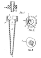
- Fig.l is a longitudinal cross-section of the hydrocyclone.
- the hydrocyclone comprises a body component 1 defining the vortex chamber and a cover component 2 therefor. For clarity, these two components are shown separated.
- Fig.2 is a plan view of the body component and Fig.3 is a plan view of the cover component.
- the vortex chamber defined by the body component 1 has a short cylindrical section 3 at one end and an adjoining tapering section 4 which occupies the major part of the length of the chamber and terminates in an apex discharge aperture 5.
- the wider end of the moulding is shaped to define a recess outwardly bounded by a rim 6 which is interrupted over part of the periphery of the moulding.
- the rebate is, over its length, in radially inward communication with that chamber.
- the radially outward wall of the rebate follows a volute path which curves progressively inwardly towards the radially symmetrical wall of the vortex chamber and merges with that wall at point 9.
- the volute subtends an angle of about 90° at the axis of the chamber
- the cover component 2 is shaped to fit into the recess bounded by the rim 6. When so fitted, the cover piece closes off the top of the groove 7 and the rebate 8 so that the groove 7 becomes the hydrocylone feed passage and rebate 8 becomes the volute guide channel.
- the cover piece includes the so-called "vortex finder" 10 which is a tubular portion which intrudes into the cylindrical section of the vortex chamber and defines the axial discharge aperture in the wider end of the hydrocyclone.
- volute makes it possible to achieve higher vortex speeds and therefore a sharper separation between starch particles and particles of insoluble protein of relatively low settling rate such as gluten particles.
- volute hydrocyclones In practice it has been found necessary to feed conventional volute hydrocyclones at a pressure which is at least 30% higher than the feed pressure employed when using hydrocyclones of the older type and of comparable size.
- volute hydrocyclones currently in use in the starch industry which have a diameter (measured at the wider end of the vortex chamber) of about 10 mm, are generally operated with a pressure drop of from 6 to 6.5 bar, whereas for achieving a similar operating throughput capacity using older type hydrocyclones it would suffice to operate at a pressure drop of 3 to 3.5 bar.
- volute hydrocyclones have been used extensively in the starch industry in many countries of the world for at least the last twenty years, nothwithstanding the need which has been widely recognised for several years to reduce energy consumption wherever possible.
- the cost of the increase in input energy necessary when using the known volute hydrocyclones is very high. For example in a nine-stage maize starch washing installation the additional 3 bar feed pressure represents an energy consumption of about 5 kwh per tonne of the processed maize.
- the present invention is based on the discovery that the feed energy requirements of the known volute hydrocyclones can be substantially reduced by the very simple expedient of increasing the hydraulic radius of the feed passage in relation to the diameter of the hydrocyclone.
- the hydraulic radius is the ratio of the cross-sectional area of the feed passage to the peripheral extent of the cross-section.
- small volute hydrocyclones have had a feed passage having a constant hydraulic radius which is less than 5.6% of the hydrocyclone diameter.
- the dimensional specifications of the small volute hydrocyclones used in the starch industry were standardised very many years ago and these provide a vortex chamber diameter of approximately 10 mm and a feed passage of uniform rectangular cross-section measuring approximately 2.2 x 2.2 mm.
- the choice of a rectangular section for the feed passage rather than a circular section which was more usual in larger hydrocyclones was desirable for facilitating manufacture by moulding.
- the hydraulic radius of the feed passage of these hydrocyclones is therefore approximately 0.55 which is 5.5% of the hydrocyclone diameter. It has been found that a very small increase in the hydraulic radius/hydrocyclone diameter ratio enables performance characteristics at least as good as those obtainable with the conventional volute hydrocyclones to be achieved with a much lower energy consumption.
- a small volute hydrocyclone according to the present invention is characterised in that the ratio of the hydraulic radius, or of the minimum hydraulic radius, of the feed passage to the diameter of the vortex chamber, is in the range 5.7 to 6.5%.
- the feed passage can be of uniform cross-section (and therefore of constant hydraulic radius) along its length, the feed passage can taper over the whole or part of its length, in either direction. In the latter case it is the minimum hydraulic radius of the feed passage which should be in the above range relative to the diameter of the vortex chamber.
- the efficiency of such a hydrocyclone can be determined for this and other purposes by determining the operating throughput capacity and the composition of the underflow (i.e. the material discharging from the apex aperture of the hydrocyclone) when feeding the hydrocyclone with a given purified starch suspension of a given density at a given temperature and under a given pressure.
- Tests 1 and 2 a conventional 10 mm volute hydrocyclone having a feed passage cross-section measuring approximately 2.2 x 2.2 mm as herinbefore referred to was used.
- the hydrocyclone was moulded from polyamide 6.6 and was as described with reference to the accompanying drawings.
- the hydrocyclone had a cone angle of 6 , and underflow (apex) discharge aperture 2.3 mm in diameter and an overflow aperture 2.5 mm in diameter.
- the hydrocyclone used in each of the other Tests was identical with the hydrocyclone used in Tests 1 and 2 except for the dimensions of the feed passage.
- Test 1 Pressure drop across hydrocyclone 4 bars
- Test 2 Pressure drop 6 bars
- the hydrocyclone was according to the present invention.
- the hydrocyclone used had a rectangular feed passage measuring 2.5 x 2.1 mm.
- the ratio of the hydraulic radius of the feed passage to the hydrocyclone diameter was therefore 5.71%.
- the relevant performance data were as follows:
- the hydrocyclone was also according to the invention.
- the hydrocyclone used had a rectangular feed passage measuring 2.5 x 2.2 mm.
- the ratio of the hydraulic radius of the feed passage to the hydrocyclone diameter was therefore 5.85%.
- the relevant performance data were as follows:
- Test 7 pressure drop 4 bars
- Test 8 pressure drop 6 bars
- a feed passage with a hydraulic radius or a minimum hydraulic radius such that the ratio of this radius to the hydrocyclone diameter is in the range 5.8 to 6.4%
- the ratio of the hydraulic radius to the diameter of the hydrocyclone should not exceed 6.5%. If the hydraulic radius is too large the residence time of the starch in the hydrocyclone will be too short.
- volute hydrocyclone with a feed passage having a hydraulic radius which is in the range 5.7 to 6.5% of the hydrocyclone diameter depends, other things being equal, on the length of the volute.
- the conventional small volute hydrocyclones have a volute subtending about 90° at the axis of the vortex chamber. Tests indicate that the performance of hydrocyclones according to the invention in terms of operating throughput capacity and starch recovery tend to improve if the volute is lengthened as suggested by the broken line 11 in Fig.2 of the accompanying drawings.
- the volute exceeds 100 0 .
- the hydrocyclone has a diameter in the range 8 to 12 mm.
- the performance of a volute hydrocyclone is influenced to some extent by the cone angle, the sizes of the overflow and underflow discharge apertures, and the length of the vortex finder intruding into the vortex chamber. This fact is well known, and it is also well known what are appropriate values of these dimensions for obtaining satisfactory performance results when using conventional small volute hydrocyclones. These various parameters have a similar influence on the performance of a volute hydrocyclone according to the present invention and appropriate values of the said dimensions can easily be selected by persons skilled in the art.
- the most suitable values of the said dimensions for hydrocyclones according to the present invention lie within the following ranges:
- the cone angle is selected having regard to the vortex chamber diameter so that the residence time of the material in the hydrocyclone will be sufficient for the separation to occur.
- the hydrocyclone has a diameter of between 8 and 12 mm.
- the most preferred cone angle range is from 4 to 8°.
- the most preferred underflow aperture sizes are from 2.2 to 2.5 mm diameter, and the most preferred range for the overflow aperture is from 2.3 to 2.7 mm.
- the conventional 10 mm volute hydrocyclones have a vortex finder whose length (distance over which the vortex finder intrudes into the vortex chamber) is approximately 3.5 mm. Tests indicate that in a volute hydrocyclone according to the present invention there may be advantages in using a longer vortex finder. It is suitable to use a vortex finder of a length in the range 2.5 to 8 mm. The vortex finder should not be so long that it has an objectionable braking action on the rotation of the suspension in the vortex chamber.
- the present invention includes a method of recovering starch from a feedstock in which the starch is entrained in a liquid medium, by passing the feedstock under pressure through hydrocyclones, characterised in that use is made of small volute hydrocyclones according to the invention as hereinbefore defined
- the pressure drop across the hydrocyclones is less than 5 bars.
- the Tests show that even when working under a pressure drop of no more than 5 bars, it is possible to achieve better results than those obtained by using conventional hydrocyclones at a pressure drop of 6 bars.
- the results can be further improved. in terms of both throughput capacity and starch recovery. Because of the higher throughput capacity, a given starch recovery can be achieved with the aid of fewer hydrocyclones than would be required if conventional hydrocyclones were used.
- Test 5 herein referred to the pressure drop across the hydrocyclone was 4 bars (the same pressure drop as in Test 1), all other conditions remaining the same as in Test 5.
- the corresponding performance data were as follows: This demonstrates the improvement in starch recovery as compared with Test 1 in which a conventional volute hydrocyclone was used at the same pressure drop.
Priority Applications (2)
| Application Number | Priority Date | Filing Date | Title |
|---|---|---|---|
| EP83306210A EP0137084A3 (fr) | 1983-10-13 | 1983-10-13 | Hydrocyclones |
| KR1019830005134A KR850003686A (ko) | 1983-10-13 | 1983-10-29 | 하이드로사이클론 |
Applications Claiming Priority (1)
| Application Number | Priority Date | Filing Date | Title |
|---|---|---|---|
| EP83306210A EP0137084A3 (fr) | 1983-10-13 | 1983-10-13 | Hydrocyclones |
Publications (2)
| Publication Number | Publication Date |
|---|---|
| EP0137084A2 true EP0137084A2 (fr) | 1985-04-17 |
| EP0137084A3 EP0137084A3 (fr) | 1986-02-19 |
Family
ID=8191312
Family Applications (1)
| Application Number | Title | Priority Date | Filing Date |
|---|---|---|---|
| EP83306210A Withdrawn EP0137084A3 (fr) | 1983-10-13 | 1983-10-13 | Hydrocyclones |
Country Status (2)
| Country | Link |
|---|---|
| EP (1) | EP0137084A3 (fr) |
| KR (1) | KR850003686A (fr) |
Cited By (3)
| Publication number | Priority date | Publication date | Assignee | Title |
|---|---|---|---|---|
| US5769243A (en) * | 1996-07-30 | 1998-06-23 | Thermo Black Clawson Inc. | Through-flow cleaner with improved inlet section |
| NL1026928C2 (nl) | 2004-08-30 | 2006-03-01 | Greenship B V | Werkwijze voor het zuiveren van ballastwater. |
| WO2021091370A1 (fr) * | 2019-11-08 | 2021-05-14 | Cyros B.V. | Dispositif et procédé de régulation de pression |
Citations (6)
| Publication number | Priority date | Publication date | Assignee | Title |
|---|---|---|---|---|
| GB473484A (en) * | 1935-04-12 | 1937-10-11 | Adam Johannes Ter Linden | Centrifugal means for the extraction of grit from flowing gases |
| CH248467A (de) * | 1945-08-11 | 1947-05-15 | Tomasini Karl | Fliehkraftabscheider. |
| US2689810A (en) * | 1953-07-22 | 1954-09-21 | Stamicarbon | Separation of starch and gluten |
| GB763291A (en) * | 1953-07-17 | 1956-12-12 | Stamicarbon | Process and apparatus for the separation of insoluble protein from a starch suspension |
| GB870606A (en) * | 1956-12-28 | 1961-06-14 | Theodore Rufus Naylor | Hydrocyclones |
| FR2099400A5 (fr) * | 1970-07-31 | 1972-03-10 | Siemens Ag |
-
1983
- 1983-10-13 EP EP83306210A patent/EP0137084A3/fr not_active Withdrawn
- 1983-10-29 KR KR1019830005134A patent/KR850003686A/ko not_active Application Discontinuation
Patent Citations (6)
| Publication number | Priority date | Publication date | Assignee | Title |
|---|---|---|---|---|
| GB473484A (en) * | 1935-04-12 | 1937-10-11 | Adam Johannes Ter Linden | Centrifugal means for the extraction of grit from flowing gases |
| CH248467A (de) * | 1945-08-11 | 1947-05-15 | Tomasini Karl | Fliehkraftabscheider. |
| GB763291A (en) * | 1953-07-17 | 1956-12-12 | Stamicarbon | Process and apparatus for the separation of insoluble protein from a starch suspension |
| US2689810A (en) * | 1953-07-22 | 1954-09-21 | Stamicarbon | Separation of starch and gluten |
| GB870606A (en) * | 1956-12-28 | 1961-06-14 | Theodore Rufus Naylor | Hydrocyclones |
| FR2099400A5 (fr) * | 1970-07-31 | 1972-03-10 | Siemens Ag |
Non-Patent Citations (1)
| Title |
|---|
| DE INGENIEUR, vol. 77, no. 2, 8th January 1965, pages W1-W8, NL; H.J. VAN EBBENHORST TENGBERGEN: "Dust cyclones - law of similarity - influence of the dust concentration" * |
Cited By (5)
| Publication number | Priority date | Publication date | Assignee | Title |
|---|---|---|---|---|
| US5769243A (en) * | 1996-07-30 | 1998-06-23 | Thermo Black Clawson Inc. | Through-flow cleaner with improved inlet section |
| NL1026928C2 (nl) | 2004-08-30 | 2006-03-01 | Greenship B V | Werkwijze voor het zuiveren van ballastwater. |
| WO2021091370A1 (fr) * | 2019-11-08 | 2021-05-14 | Cyros B.V. | Dispositif et procédé de régulation de pression |
| NL1043455B1 (nl) * | 2019-11-08 | 2021-07-20 | Cyros B V | Inrichting en werkwijze voor het regelen van druk |
| CN114929988A (zh) * | 2019-11-08 | 2022-08-19 | 赛洛斯私营有限责任公司 | 用于调节压力的装置和方法 |
Also Published As
| Publication number | Publication date |
|---|---|
| KR850003686A (ko) | 1985-06-26 |
| EP0137084A3 (fr) | 1986-02-19 |
Similar Documents
| Publication | Publication Date | Title |
|---|---|---|
| JPS6082156A (ja) | ハイドロサイクロン | |
| CA1045083A (fr) | Hydrocyclone | |
| US3130157A (en) | Hydro-cyclones | |
| US6024874A (en) | Hydrocyclone separator | |
| CA1160576A (fr) | Methode et dispositif de separation par centrifugation | |
| US3971718A (en) | Hydrocyclone separator or classifier | |
| US2829771A (en) | Process and apparatus for classifying solid materials in a hydrocyclone | |
| US3507397A (en) | Hydrocyclone unit | |
| US4175036A (en) | Hydrocyclone separator | |
| US3568847A (en) | Hydrocyclone | |
| CA1288731C (fr) | Hydrocyclone separateur a recuperation de fibres | |
| JPH0330420B2 (fr) | ||
| FI58954B (fi) | Hydrocyklon | |
| US4151083A (en) | Apparatus and method for separating heavy impurities from feed stock | |
| US3425545A (en) | Method and apparatus for separating fibrous suspensions | |
| US4153558A (en) | Hydrocyclone separator | |
| EP0234101B1 (fr) | Hydrocyclone inverse pour débarrasser une suspension de fibres des impuretés légères | |
| US3807142A (en) | Method and apparatus for high efficiency removal of gases and particles from paper pulp suspensions and other fluids | |
| US3433362A (en) | Cyclone purifier | |
| US4510056A (en) | Hydrocyclone separator | |
| US3764005A (en) | Hydrocyclone pulp cleaner | |
| US2701056A (en) | Method and apparatus for classifying and concentrating materials | |
| CN2882798Y (zh) | 新型轴流式高效水力旋流器 | |
| US2981413A (en) | Process for separating solids in liquid suspension | |
| EP0137084A2 (fr) | Hydrocyclones |
Legal Events
| Date | Code | Title | Description |
|---|---|---|---|
| PUAI | Public reference made under article 153(3) epc to a published international application that has entered the european phase |
Free format text: ORIGINAL CODE: 0009012 |
|
| AK | Designated contracting states |
Designated state(s): AT BE CH DE FR GB IT LI LU NL SE |
|
| PUAL | Search report despatched |
Free format text: ORIGINAL CODE: 0009013 |
|
| AK | Designated contracting states |
Designated state(s): AT BE CH DE FR GB IT LI LU NL SE |
|
| STAA | Information on the status of an ep patent application or granted ep patent |
Free format text: STATUS: THE APPLICATION IS DEEMED TO BE WITHDRAWN |
|
| 18D | Application deemed to be withdrawn |
Effective date: 19861020 |
|
| RIN1 | Information on inventor provided before grant (corrected) |
Inventor name: VEGTER, HERMAN JOHAN |