EP0137036B1 - High force-gain valve - Google Patents
High force-gain valve Download PDFInfo
- Publication number
- EP0137036B1 EP0137036B1 EP84901269A EP84901269A EP0137036B1 EP 0137036 B1 EP0137036 B1 EP 0137036B1 EP 84901269 A EP84901269 A EP 84901269A EP 84901269 A EP84901269 A EP 84901269A EP 0137036 B1 EP0137036 B1 EP 0137036B1
- Authority
- EP
- European Patent Office
- Prior art keywords
- gate
- fluid
- housing
- force
- diverter
- Prior art date
- Legal status (The legal status is an assumption and is not a legal conclusion. Google has not performed a legal analysis and makes no representation as to the accuracy of the status listed.)
- Expired
Links
Images
Classifications
-
- F—MECHANICAL ENGINEERING; LIGHTING; HEATING; WEAPONS; BLASTING
- F16—ENGINEERING ELEMENTS AND UNITS; GENERAL MEASURES FOR PRODUCING AND MAINTAINING EFFECTIVE FUNCTIONING OF MACHINES OR INSTALLATIONS; THERMAL INSULATION IN GENERAL
- F16K—VALVES; TAPS; COCKS; ACTUATING-FLOATS; DEVICES FOR VENTING OR AERATING
- F16K39/00—Devices for relieving the pressure on the sealing faces
- F16K39/02—Devices for relieving the pressure on the sealing faces for lift valves
Abstract
Description
- This invention relates to high force-gain valves.
- Many different types of valves are used to control the flow of fluids. Particular difficulties can arise, however, in valves which are employed to control fluids under high pressure. Force-gain can be defined as the ratio of the output force to the input force. Many typically-configured prior art valves have low force-gain and require a relatively powerful actuator to overcome the force of the high pressure fluid to which the valve component which varies the fluid flow is exposed. , For example, in a typical poppet valve having a force-gain of only 1.5, the actuator would have to supply a force of 8896 N (2000 lbf) in order to open a 645 mm2 (1 in2) poppet against a fluid at a pressure of 20.69 kPa (3000 Ibf/in2). In addition to being expensive and bulky, such powerful actuators are heavy, a disadvantage where overall valve weight is an important factor, such as in aircraft or guided missile applications. Further, the necessity for such a powerful actuator eliminates from the choice of potential actuator types the typically smaller, lower powered and less expensive actuators, such as solenoids and cams.
- Certain valve applications may also require quick opening, closing and precise positioning of the valve. For example, valves used as directional control thrusters in missile propulsion and control systems necessitate precisely timed, short bursts of high pressure fluid from the valves. The bulky, powerful actuators described earlier, used in many prior art valves to control the flow of high pressure fluid, do not however lend themselves to quick opening and closing as do the lower powered actuators, such as solenoids and small servoactuators. Thus, fast reaction can be difficult to achieve in a high pressure valve.
- Document EP-A-0 074 508, which forms part of the state of the art as regards the present application only by virtue of EPC Article 54(3), discioses a high force-gain valve for fluid flow control which bears some similarity to such valves embodying the present invention as described hereinbelow.
- Document US―A―2 087 037 discloses a high force-gain valve for controlling the flow of fluid therethrough, the valve comprising:
- (a) a housing having first and second openings therein, one of the openings being in fluid communication with a source of the fluid or being capable of being put into fluid communication with such a source;
- (b) a fluid diverter;
- (c) support means mounting the fluid diverter in a fixed position within the housing so that the fluid diverter is aligned with and spaced from the second opening;
- (d) a gate disposed within the housing, the gate closely surrounding the diverter and having a substantially force balanced configuration, the gate being translatable between open and closed positions and including a sealing edge so sized and shaped that, when the gate is in the closed position, the sealing edge will seat against a portion of the housing adjacent the second opening thereby blocking flow of the fluid therethrough, and the gate being hollow with the interior of the gate being in fluid communication with the interior of the housing, thereby facilitating the force balancing thereof; and
- (e) actuation means for effecting translation and positioning of the gate between the open and closed positions.
- The present invention provides a high force-gain valve as just described, characterised in that both the diverter and the diverter support means are positioned on the same side of and are spaced from the second opening so that the diverter support means does not obstruct fluid flow through the second opening, the diverter is substantially hollow and includes elongated slots through a wall thereof aligned parallel to the direction of translation of the gate, and the gate includes spokes sized for being received in the slots.
- The US-document mentioned above presents supporting webs in the flow stream, which occupy flow area. This requires larger diameter components and increases the weight and volume of the valve.
- The invention will now be further described, by way of illustrative and non-limiting example, with reference to the accompanying drawings, wherein:
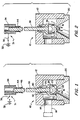
- Fig. 1 is a cross-sectional visw of a high force-gain valve embodying the present invention showing a gate thereof in a closed position;
- Fig. 2 is a cross-sectional view of the valve showing the gate in an open position.
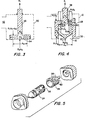
- Fig. 3 is a cross-sectional view of a prior art poppet valve;
- Fig. 4 is a cross-sectional view of the gate and a diverter of the valve embodying the present invention, showing force balancing areas and pressures thereof;
- Fig. 5 is a perspective view of slots in the diverter and ribs in the gate; and
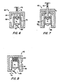
- Figs 6 to 8 are cross-sectional views of alternative embodiments of fast reaction valve in accordance with the present invention.
- Turning now to a consideration of the drawings, and in particular to Fig. 1, there is shown a high force-
gain valve 10 embodying the present invention which is employed to control the flow of a fluid therethrough. Thevalve 10 includes ahousing 12 which has at least afirst opening 14 and asecond opening 16. One of the openings, in this case thefirst opening 14, is in fluid communication with a source of fluid, such as aninlet hose 18 shown in dashed lines. In the configuration shown in Fig. 1, thevalve 10 is used as a control thruster and therefore a portion of thehousing 12 comprises anozzle 20 which is attached to he remainder of thehousing 12 in an appropriate manner, such as with a threaded screw arrangement. As can be seen, thesecond opening 16 comprises theentrance 22 of thenozzle 20. Of course, thevalve 10 can have many other uses and thus thehousing 20 can have any shape appropriate to such uses. - The
valve 10 includes a fluid diverter 24 fixed in position and disposed within thehousing 12. Thediverter 24 is shaped to divert, or direct, the fluid flowing through thesecond opening 16 and is thus aligned with and spaced from the second opening. In the configuration of Fig. 1, thediverter 24 is generally cone shaped with the pointed center portion of the diverter extending into thenozzle 20 beyond theentrance 22. The shape of the diverter, however, can be modified as desired. - The
diverter 24 is attached to thehousing 12 in a manner so as to provide an unobstructed fluid flowpath through thesecond opening 16. For example, thediverter 24 can include anextension 26 having a threaded end which screws into a corresponding threaded section of thehousing 12. Thus, no support structures extend through the second opening which might interfere with the fluid flow. - The
valve 10 varies the flow of fluid therethrough by means of atranslatable gate 28 disposed within thehousing 12 and which closely surrounds thediverter 24. A seal, such as the O-ring seal 25, can be disposed between thegate 28 and thediverter 24 to prevent fluid leakage along their interface. Fig. 1 shows thegate 28 in a closed position while Fig. 2 shows it in an open position. Thegate 28 includes a sealing edge 30 which is sized and shaped for, when thegate 28 is in the closed position of Fig. 1, seating against a portion of thehousing 12, in this case against thenozzle 20, adjacent thesecond opening 16 to thereby block the flow of fluid therethrough. When thegate 28 is translated to the open position of Fig. 2, fluid flows past the gate and thediverter 24 and through the second opening 16. Thegate 28 can also be positioned at intermediate positions between the open and closed positions to permit a reduced amount of fluid to flow through the second opening. - The
valve 10 includes actuation means for effecting translation and positioning of thegate 28 between the open and closed positions. One example of suitable actuation means comprises asolenoid positioner 31 shown in Figs. 1 and 2. Thesolenoid positioner 31 comprises anelectric power source 32 connected to acoil 34 through aswitch 36. Thegate 28 includes astem 38 which extends through anaperture 40 in thehousing 12 to the center of thecoil 34. Thehousing 12 can include aseal 42 abutting thestem 38 to prevent leakage. When theswitch 36 is open, as in Fig. 1, thecoil 34 is deenergized and aspring 44, which is disposed to cooperate with thestem 38, exerts a force against aflange 46 on thestem 38 to translate thegate 28 to and maintain it in the closed position. Thespring 44 thus also provides a fail safe feature to the valve in that should thepositioner 31 fail, thegate 28 will be closed. When theswitch 36 is closed, on the other hand, as is seen in Fig. 2, thepositioner 31 is activated, thecoil 34 being energized by theelectric power source 32. Thestem 38, which is made of an appropriate magnetic material, is pulled up into thecoil 34 by the electromagnetic field created therein, overcoming the force of thespring 44, thereby translating thegate 28 to the open position. The above describedsolenoid positioner 31 is presented as an example only and numerous other actuation means can also be employed with thevalve 10. - A feature of the
valve 10 is that thegate 28 has a substantially force balanced configuration. As a result, thevalve 10 has high force-gain and thus relatively low powered, lightweight and therefore inexpensive actuation means can be used to quickly translate thegate 28, even under high fluid pressure. The force balancing configuration can best be explained by reference to Figs. 3 and 4. Fig. 3 shows a typical prior art poppet valve which is not force balanced. F1 represents the actuation force required to open thepoppet 48 when the fluud pressure P1 inside thehousing 50 is greater than the fluid pressure P2 on the outside of thehousing 50. In that case, the opening 52 would be the fluid inlet while the opening 54 would be the fluid outlet. At is the total surface area across the poppet, As is the area of the stem and Ao is the area of the opening covered by the poppet. In order to open thepoppet 48, the actuation force F1 must exceed the force of the fluid pressure P1. acting upon the exposed inner surface area of thepoppet 48, A,-As. - Where P2 is small relative to P1, as would typically be the case with a fluid valve, the pressure P2 acting upon the exposed outer surface area of the
poppet 48, which would equal Ao, would offer little assitance to the actuation force F1. Thus, neglecting the effects of P2 and any friction forces involved, the valve actuation means must be capable of providing a force F1 which exceeds the force P1 (At-As) in order to open thepoppet 48. - For comparison, reference is now made to Fig. 4 where there is shown a valve embodying the present invention which has a force balanced configuration. The
housing 12 is filled with fluid and thegate 28 is completely immersed therein. The area of the stem As and the total surface area At of thegate 28 in Fig. 4 are the same as the corresponding areas As and At of thepoppet 48 of Fig. 3, and the area An of thesecond opening 16 of Fig. 4 is the same as the area Ao of Fig. 3. Likewise, the pressures P1 and P2 are the same for the valves of both figures. However, the configuration of thegate 28 differs significantly from that of thepoppet 48 resulting in its being substantially force balanced. Thegate 28 is hollow and thediverter 24 which it surrounds is also hollow. The interior of thegate 28 is in fluid communication with the interior of thehousing 12 throughapertures 56 in thegate 28. Thus, the pressure P1 on the interior of thegate 28 is the same as the pressure P1 in the interior of thehousing 12. Briefly referring to Fig. 5, the hollow configuration of thegate 28 and its relationship to thediverter 24 can be more easily seen. Thediverter 24 includeselongated slots 58 through a wall thereof aligned parallel to the direction of translation of thegate 28. Thegate 28 includes spokes 60 sized and aligned for being received in theslots 58. When thegate 28 is translated between the open and closed positions, the spokes 60 slide within theslots 58. Theapertures 56 which provide fluid communication between the interior of thegate 28 and the interior of thehousing 12 comprise the open areas between the spokes 60. As will be explained shortly, the equal pressures P, on both the inside and outside of thegate 28 promotes the force balancing thereof. - Referring to Fig. 4, another feature adding to the force balancing of the
gate 28 comprises the sealing edge 30 of thegate 28 being beveled, exposing most of the sealing edge to the pressure P, of the fluid in the interior of thehousing 12. The beveled edge could be either straight as is shown or could have a curving, tapered shape, as is shown in Figs. 1 and 2. Returning to Fig. 4, only the apex of the sealing edge 30 seats against the portion of thehousing 12 adjacent thesecond opening 16 when the gate is in the closed position. Thus, the pressure P, acts upon both the upper and lower (sealing edge) ends of the sidewall of thegate 28. - Considering the forces which the actuator force F, must overcome in order to translate the
gate 28 to the open position, the component of the exterior pressure P2 parallel to the direction of gate translation acts only upon the fixeddiverter 24 and thus has no effect upon gate translation. The area As of the gate wall is acted upon by the fluid pressure P, not only on its upper wall but also upon the beveled sealing edge 30. The area Ak of the spokes 60 is acted upon by the fluid pressure P, both on the upper and lower surfaces thereof due to the presence of fluid in the interior of and exterior to thegate 28. Finally, only the lower, and not the upper, surface of the area As of the stem is acted upon by the fluid pressure Pi. Thus, neglecting friction forces, in order to translate thegate 28 to the open position, the actuation force F1 must exceed the force
stem 38. This force, P1As, being in an upward direction, tends to translate the gate to an open position and thus actually assists the actuation means in opening the gate. A spring, similar to thespring 44 shown in Fig. 1, is included in the actuation means to provide a closing force closely balancing the opening force P1As. Thus, the gate opening actuation force Fi, such as that provided by the energizing of thecoil 34 in Fig. 1, can be quite small and thegate 28 can be translated very quickly since the other forces acting upon thegate 28 are in substantial balance. Likewise, since thegate 28 is substantially force balanced in its open, closed and all intermediate positions, the force required to translate the gate in any direction or to maintain it in any position will be very small. Thus, the force required to translate thegate 28 from the open to the closed positions can be provided by the spring configured to exert a downward closing force slightly in excess of P1As. The force balancing of thegate 28 also facilitates precise positioning thereof to any desired position. In terms of force-gain, the valve output, or movement of thegate 28 against even a high pressure fluid, requires a very low input, or actuation force F1. The force-gain, or ratio of the output force to the input force, is therefore quite high. As a result, the actuation means for the high force-gain valve 10 can be smaller, lighter and less expensive that that which would be required for the prior art poppet valve of Fig. 3 which, as was explained earlier, would have to provide a force exceeding P1 (At-As) in order to open thepoppet 48. - A similar comparison could be made between the prior art poppet valve of Fig. 3 and the high force-gain valve of Fig. 4 when the pressure P2 on the outside of the valve exceeds the pressure P1 on the inside of the valve. The force required to maintain the
poppet 48 of Fig. 3 in the closed position would have to be at least P2Ao, while the force required to maintain thegate 28 in the closed position in Fig. 4 would be virtually zero, since the vertical component of P2 acts only upon thediverter 24 which is fixed in position. Thus, the fast reaction valve of Fig. 4 is substantially force balanced whether P1 exceeds or is less than P2, thereby allowing quick opening and closing and precise positioning of thegate 28 using small, light actuation means. - Figs. 6 to 8 show alternative embodiments of the high force-gain valve of the present invention. In each of these embodiments, the actuation means is shown as comprising a spring disposed to cooperate with either the gate or a stem extending from the gate to urge the gate to translate in a preselected direction. The spring has a spring force selected to permit fluid of a predetermined pressure to overcome the spring force and translate the gate in the opposite direction. Thus, the spring arrangement permits the gate to open and close automatically in response to fluid pressure. It is to be understood, however, that other actuation means, such as, for example, the
solenoid positioner 31 of Figs. 1 and 2, could also be used with these alternative embodiments as well. - Turning to Fig. 6, this embodiment of the high force-
gain valve 62 is similar to that shown in Fig. 1 and includes a housing 64 having first andsecond openings second opening 68 and a hollow, translatable gate 72 closely surrounds the diverter 70, the interior of the gate being in fluid communication with the interior of the housing 64 throughapertures 74. The gate 72 includes astem 76 extending through the housing 64 to aspring 78 which exerts a downward, closing force on the gate. The valve 72 is configured to open automatically when the fluid pressure P1 within the housing 64 exceeds a preselected value. As was explained earlier, the gate 72 is substantially force balanced, the net force on the gate being the fluid pressure P1 acting upon the cross sectional area As of thestem 76 in an upward, or gate opening, direction. When it is desired that pressures above a specific pressure P1 automatically open the gate 72, aspring 78 is selected which has a spring force equal to P1As. Any pressure above P1 will overcome the spring force and open the gate 72. When the pressure drops below P1, the spring force will force the gate 72 to a closed position. - Turning to Fig. 7, there is shown another embodiment of a high force-
gain valve 80 which is similar to thevalve 62 of Fig. 6 except that thegate 82 and the first opening 84 are configured and cooperate to provide flow feedback to the valve. As thegate 82 is translated toward the open position by the force P1As, the upper portion of the gate will begin to block off the first opening 84, reducing the amount of fluid which can flow into thehousing 86 while at the same time increasing the amount of fluid which exits the housing through the second opening 88. Thus, the fluid pressure P1 within thehousing 86 andgate 82 will decrease, permitting the force of thespring 90 to translate the gate toward the closed position. - Turning now to Fig. 8, there is shown still another embodiment of a high force-
gain valve 92. Thevalve 92 is configured in the manner of a simple relief valve such that thegate 94 will open when the fluid pressure P2 external to thehousing 96 exceeds a preselected value. As can be seen, most of the beveled sealingedge 98 is exposed to the external fluid pressure P2 at thesecond opening 99 while the corresponding upper edge of the gate is exposed to the pressure P1 within thehousing 96. The remainder of thegate 94 is force balanced, being exposed to the pressure P1 on the upper and lower surfaces thereof. Thevalve 92 also includes aspring 100 disposed between thehousing 96 and the upper portion of thegate 94 with a spring force opposing the opening of thegate 94. The fluid pressure P2 will open thegate 94 when P2Ag exceeds P,A9 plus the spring force. When P2 then decreases, thegate 94 will be translated to the closed position by the force of thespring 100 and the force exerted by the pressure P1.
Claims (9)
Applications Claiming Priority (2)
| Application Number | Priority Date | Filing Date | Title |
|---|---|---|---|
| US06/470,810 US4477056A (en) | 1983-02-28 | 1983-02-28 | High force-gain valve |
| US470810 | 1990-01-26 |
Publications (2)
| Publication Number | Publication Date |
|---|---|
| EP0137036A1 EP0137036A1 (en) | 1985-04-17 |
| EP0137036B1 true EP0137036B1 (en) | 1988-04-27 |
Family
ID=23869143
Family Applications (1)
| Application Number | Title | Priority Date | Filing Date |
|---|---|---|---|
| EP84901269A Expired EP0137036B1 (en) | 1983-02-28 | 1984-02-27 | High force-gain valve |
Country Status (8)
| Country | Link |
|---|---|
| US (1) | US4477056A (en) |
| EP (1) | EP0137036B1 (en) |
| JP (1) | JPS59159473A (en) |
| KR (1) | KR920005755B1 (en) |
| CA (1) | CA1233391A (en) |
| DE (1) | DE3470790D1 (en) |
| IL (1) | IL70960A (en) |
| WO (1) | WO1984003344A1 (en) |
Families Citing this family (12)
| Publication number | Priority date | Publication date | Assignee | Title |
|---|---|---|---|---|
| JPS6224088A (en) * | 1985-07-23 | 1987-02-02 | Esutetsuku:Kk | Control valve |
| US4995587A (en) * | 1989-11-03 | 1991-02-26 | Martin Marietta Corporation | Motion amplifier employing a dual piston arrangement |
| US5074521A (en) * | 1990-04-05 | 1991-12-24 | Martin Marietta Corporation | High force-gain valve |
| GB2246615B (en) * | 1990-08-03 | 1994-02-23 | British Gas Plc | Gas pressure control valve cartridge |
| USH1098H (en) | 1991-02-20 | 1992-09-01 | Hallum Charles E | Integrated valve assembly |
| DE9306401U1 (en) * | 1993-04-28 | 1993-07-15 | Niehueser, Hermann, Dipl.-Ing., 4831 Langenberg, De | |
| DE59506894D1 (en) * | 1995-02-15 | 1999-10-28 | Denison Hydraulik Gmbh | Direct operated hydraulic pressure valve |
| US6276125B1 (en) * | 1998-12-17 | 2001-08-21 | Alliedsignal, Inc. | Pressure balanced poppet valve |
| US20030178530A1 (en) * | 2002-01-31 | 2003-09-25 | Marotta Scientific Controls, Inc. | System for decreasing the speed of a moving craft |
| US7016014B2 (en) | 2004-02-27 | 2006-03-21 | Asml Netherlands B.V | Lithographic apparatus and device manufacturing method |
| US7090194B2 (en) * | 2004-07-27 | 2006-08-15 | Sampson Richard J | Self-priming drain valve |
| US10131530B2 (en) * | 2014-05-23 | 2018-11-20 | David S. Smith America, Inc. | Liquid dispenser with valve |
Family Cites Families (17)
| Publication number | Priority date | Publication date | Assignee | Title |
|---|---|---|---|---|
| US642039A (en) * | 1899-07-24 | 1900-01-23 | William L Garrels | Throttle-valve. |
| US1729802A (en) * | 1923-11-02 | 1929-10-01 | Wallace W Smith | Appliance for internal-combustion engines |
| US1649953A (en) * | 1924-10-15 | 1927-11-22 | Charles A Ernst | Double-gate balanced valve |
| US1752439A (en) * | 1926-10-14 | 1930-04-01 | I P Morris And De La Vergne In | Sleeve valve |
| US2087037A (en) * | 1935-02-21 | 1937-07-13 | Klipfel Mfg Company | Valve |
| US2091669A (en) * | 1935-09-07 | 1937-08-31 | Westinghouse Electric & Mfg Co | Elastic fluid turbine |
| US2638108A (en) * | 1949-06-24 | 1953-05-12 | Power Brake Equipment Co | Push-pull control valve |
| US2921603A (en) * | 1957-02-12 | 1960-01-19 | Chaplin Fulton Mfg Company | Double ported poppet valve |
| US3121444A (en) * | 1960-07-13 | 1964-02-18 | Bering Jorgen Dietz | Balanced valves |
| US3680832A (en) * | 1969-03-20 | 1972-08-01 | Nikex Nehezipari Kulkere | Closure device for streaming media, in particular high pressure liquids |
| US3601147A (en) * | 1969-03-28 | 1971-08-24 | Honeywell Inc | Semibalanced plug valve |
| US4004605A (en) * | 1973-08-02 | 1977-01-25 | Titovi Zavodi Litostroj Ljubljana N.Sol.O. | Relief valve for fluids |
| US3892384A (en) * | 1974-04-12 | 1975-07-01 | Honeywell Inc | Double seated cage valve with flexible plug seat |
| JPS6113819Y2 (en) * | 1978-10-20 | 1986-04-28 | ||
| FR2461864A1 (en) * | 1979-07-19 | 1981-02-06 | Centre Techn Ind Mecanique | ANTI-VIBRATION VALVE |
| IT1123188B (en) * | 1979-09-17 | 1986-04-30 | Nuovo Pignone Spa | BALANCED SHUTTER VALVE |
| US4500070A (en) * | 1981-08-25 | 1985-02-19 | Alsthom-Atlantique | Valve for adjusting the rate of flow of a gaseous fluid |
-
1983
- 1983-02-28 US US06/470,810 patent/US4477056A/en not_active Expired - Lifetime
-
1984
- 1984-02-01 CA CA000446577A patent/CA1233391A/en not_active Expired
- 1984-02-13 JP JP59023025A patent/JPS59159473A/en active Granted
- 1984-02-14 IL IL70960A patent/IL70960A/en unknown
- 1984-02-25 KR KR1019840000923A patent/KR920005755B1/en not_active IP Right Cessation
- 1984-02-27 EP EP84901269A patent/EP0137036B1/en not_active Expired
- 1984-02-27 DE DE8484901269T patent/DE3470790D1/en not_active Expired
- 1984-02-27 WO PCT/US1984/000274 patent/WO1984003344A1/en active IP Right Grant
Also Published As
| Publication number | Publication date |
|---|---|
| KR840007946A (en) | 1984-12-11 |
| JPH0447194B2 (en) | 1992-08-03 |
| US4477056A (en) | 1984-10-16 |
| JPS59159473A (en) | 1984-09-10 |
| KR920005755B1 (en) | 1992-07-18 |
| EP0137036A1 (en) | 1985-04-17 |
| WO1984003344A1 (en) | 1984-08-30 |
| IL70960A (en) | 1989-09-10 |
| CA1233391A (en) | 1988-03-01 |
| DE3470790D1 (en) | 1988-06-01 |
| IL70960A0 (en) | 1984-05-31 |
Similar Documents
| Publication | Publication Date | Title |
|---|---|---|
| EP0137036B1 (en) | High force-gain valve | |
| US4848721A (en) | Hydraulic valve with integrated solenoid | |
| AU657661B2 (en) | Boom control valve | |
| US3511469A (en) | Solenoid operated valve | |
| US3405906A (en) | Solenoid pilot operated valve | |
| US5964446A (en) | Elastomeric element valve | |
| US4967791A (en) | Pressure activated check valve | |
| US3957244A (en) | Valve | |
| US5474107A (en) | Fail-open solenoid actuated valve | |
| US6943657B2 (en) | Solenoid and valve assembly having a linear output | |
| FI66065B (en) | GENOMSTROEMNINGSVENTIL | |
| US4782862A (en) | Solenoid valve | |
| CA2113024A1 (en) | High Pressure Relief System | |
| US5064166A (en) | Solenoid valve with high flow capacity and low energy consumption | |
| US3905575A (en) | Three stage solenoid operated valve assembly | |
| US3493008A (en) | Pressure balanced regulating valve | |
| WO1995006835A1 (en) | Fail-open solenoid actuated valve | |
| EP0461331B1 (en) | Three way valve | |
| JP2004069069A (en) | Solenoid operating pressure control valve | |
| US4666125A (en) | Low leakage solenoid valve | |
| US4527772A (en) | Modulating control valve | |
| US5117868A (en) | Pilot-controlled directional valve | |
| JPH0369875A (en) | Solenoid valve | |
| US4825916A (en) | Flow control valve | |
| JP2871568B2 (en) | Solenoid valve with manual override |
Legal Events
| Date | Code | Title | Description |
|---|---|---|---|
| PUAI | Public reference made under article 153(3) epc to a published international application that has entered the european phase |
Free format text: ORIGINAL CODE: 0009012 |
|
| 17P | Request for examination filed |
Effective date: 19841113 |
|
| AK | Designated contracting states |
Designated state(s): CH DE FR GB LI NL SE |
|
| 17Q | First examination report despatched |
Effective date: 19860922 |
|
| GRAA | (expected) grant |
Free format text: ORIGINAL CODE: 0009210 |
|
| AK | Designated contracting states |
Kind code of ref document: B1 Designated state(s): CH DE FR GB LI NL SE |
|
| REF | Corresponds to: |
Ref document number: 3470790 Country of ref document: DE Date of ref document: 19880601 |
|
| ET | Fr: translation filed | ||
| PLBE | No opposition filed within time limit |
Free format text: ORIGINAL CODE: 0009261 |
|
| STAA | Information on the status of an ep patent application or granted ep patent |
Free format text: STATUS: NO OPPOSITION FILED WITHIN TIME LIMIT |
|
| 26N | No opposition filed | ||
| PGFP | Annual fee paid to national office [announced via postgrant information from national office to epo] |
Ref country code: FR Payment date: 19930114 Year of fee payment: 10 |
|
| PGFP | Annual fee paid to national office [announced via postgrant information from national office to epo] |
Ref country code: GB Payment date: 19930119 Year of fee payment: 10 Ref country code: CH Payment date: 19930119 Year of fee payment: 10 |
|
| PGFP | Annual fee paid to national office [announced via postgrant information from national office to epo] |
Ref country code: SE Payment date: 19930120 Year of fee payment: 10 |
|
| PGFP | Annual fee paid to national office [announced via postgrant information from national office to epo] |
Ref country code: DE Payment date: 19930125 Year of fee payment: 10 |
|
| PGFP | Annual fee paid to national office [announced via postgrant information from national office to epo] |
Ref country code: NL Payment date: 19930228 Year of fee payment: 10 |
|
| PG25 | Lapsed in a contracting state [announced via postgrant information from national office to epo] |
Ref country code: GB Effective date: 19940227 |
|
| PG25 | Lapsed in a contracting state [announced via postgrant information from national office to epo] |
Ref country code: SE Effective date: 19940228 Ref country code: LI Effective date: 19940228 Ref country code: CH Effective date: 19940228 |
|
| PG25 | Lapsed in a contracting state [announced via postgrant information from national office to epo] |
Ref country code: NL Effective date: 19940901 |
|
| NLV4 | Nl: lapsed or anulled due to non-payment of the annual fee | ||
| GBPC | Gb: european patent ceased through non-payment of renewal fee |
Effective date: 19940227 |
|
| PG25 | Lapsed in a contracting state [announced via postgrant information from national office to epo] |
Ref country code: FR Effective date: 19941031 |
|
| REG | Reference to a national code |
Ref country code: CH Ref legal event code: PL |
|
| PG25 | Lapsed in a contracting state [announced via postgrant information from national office to epo] |
Ref country code: DE Effective date: 19941101 |
|
| REG | Reference to a national code |
Ref country code: FR Ref legal event code: ST |
|
| EUG | Se: european patent has lapsed |
Ref document number: 84901269.5 Effective date: 19940910 |