EP0136867B1 - Rollers with oriented fibre reinforcement and method of making them - Google Patents
Rollers with oriented fibre reinforcement and method of making them Download PDFInfo
- Publication number
- EP0136867B1 EP0136867B1 EP84306401A EP84306401A EP0136867B1 EP 0136867 B1 EP0136867 B1 EP 0136867B1 EP 84306401 A EP84306401 A EP 84306401A EP 84306401 A EP84306401 A EP 84306401A EP 0136867 B1 EP0136867 B1 EP 0136867B1
- Authority
- EP
- European Patent Office
- Prior art keywords
- roller
- hub
- elastomeric
- fibre strands
- rubber
- Prior art date
- Legal status (The legal status is an assumption and is not a legal conclusion. Google has not performed a legal analysis and makes no representation as to the accuracy of the status listed.)
- Expired
Links
- 239000000835 fiber Substances 0.000 title claims description 67
- 238000004519 manufacturing process Methods 0.000 title claims description 9
- 230000002787 reinforcement Effects 0.000 title description 5
- 229920001971 elastomer Polymers 0.000 claims description 114
- 150000001875 compounds Chemical class 0.000 claims description 25
- 239000002344 surface layer Substances 0.000 claims description 18
- 239000000806 elastomer Substances 0.000 claims description 11
- 238000000034 method Methods 0.000 claims description 10
- 239000010410 layer Substances 0.000 claims description 8
- 239000005020 polyethylene terephthalate Substances 0.000 claims description 7
- 238000005520 cutting process Methods 0.000 claims description 6
- -1 for example Polymers 0.000 claims description 5
- 229920004934 Dacron® Polymers 0.000 claims description 4
- 229920000271 Kevlar® Polymers 0.000 claims description 4
- 229920000784 Nomex Polymers 0.000 claims description 4
- 239000004761 kevlar Substances 0.000 claims description 4
- 239000004763 nomex Substances 0.000 claims description 4
- JOYRKODLDBILNP-UHFFFAOYSA-N Ethyl urethane Chemical compound CCOC(N)=O JOYRKODLDBILNP-UHFFFAOYSA-N 0.000 claims description 3
- 239000000853 adhesive Substances 0.000 claims description 3
- 230000001070 adhesive effect Effects 0.000 claims description 3
- 239000004760 aramid Substances 0.000 claims description 3
- 229920003235 aromatic polyamide Polymers 0.000 claims description 3
- 239000006185 dispersion Substances 0.000 claims description 3
- 239000000463 material Substances 0.000 claims description 3
- 150000002825 nitriles Chemical class 0.000 claims description 3
- 229920001084 poly(chloroprene) Polymers 0.000 claims description 3
- 229920000139 polyethylene terephthalate Polymers 0.000 claims description 3
- 238000005096 rolling process Methods 0.000 claims 1
- 239000005060 rubber Substances 0.000 description 103
- 238000003801 milling Methods 0.000 description 5
- 238000010058 rubber compounding Methods 0.000 description 4
- 238000009472 formulation Methods 0.000 description 3
- 238000010348 incorporation Methods 0.000 description 3
- 239000002184 metal Substances 0.000 description 3
- 229910052751 metal Inorganic materials 0.000 description 3
- 239000000203 mixture Substances 0.000 description 3
- 230000002028 premature Effects 0.000 description 3
- 229910000831 Steel Inorganic materials 0.000 description 2
- XLOMVQKBTHCTTD-UHFFFAOYSA-N Zinc monoxide Chemical compound [Zn]=O XLOMVQKBTHCTTD-UHFFFAOYSA-N 0.000 description 2
- 238000005299 abrasion Methods 0.000 description 2
- 238000012423 maintenance Methods 0.000 description 2
- 239000010959 steel Substances 0.000 description 2
- 238000005303 weighing Methods 0.000 description 2
- 244000025254 Cannabis sativa Species 0.000 description 1
- 235000012766 Cannabis sativa ssp. sativa var. sativa Nutrition 0.000 description 1
- 235000012765 Cannabis sativa ssp. sativa var. spontanea Nutrition 0.000 description 1
- 229920000742 Cotton Polymers 0.000 description 1
- 239000004606 Fillers/Extenders Substances 0.000 description 1
- 239000004677 Nylon Substances 0.000 description 1
- 239000004952 Polyamide Substances 0.000 description 1
- 235000021355 Stearic acid Nutrition 0.000 description 1
- 230000002411 adverse Effects 0.000 description 1
- 230000032683 aging Effects 0.000 description 1
- 235000009120 camo Nutrition 0.000 description 1
- 239000006229 carbon black Substances 0.000 description 1
- 235000005607 chanvre indien Nutrition 0.000 description 1
- 238000010276 construction Methods 0.000 description 1
- 238000005336 cracking Methods 0.000 description 1
- 230000006378 damage Effects 0.000 description 1
- 230000000593 degrading effect Effects 0.000 description 1
- 238000013461 design Methods 0.000 description 1
- 238000011161 development Methods 0.000 description 1
- 230000018109 developmental process Effects 0.000 description 1
- 230000000694 effects Effects 0.000 description 1
- 239000003063 flame retardant Substances 0.000 description 1
- 239000011487 hemp Substances 0.000 description 1
- 229920001778 nylon Polymers 0.000 description 1
- QIQXTHQIDYTFRH-UHFFFAOYSA-N octadecanoic acid Chemical compound CCCCCCCCCCCCCCCCCC(O)=O QIQXTHQIDYTFRH-UHFFFAOYSA-N 0.000 description 1
- OQCDKBAXFALNLD-UHFFFAOYSA-N octadecanoic acid Natural products CCCCCCCC(C)CCCCCCCCC(O)=O OQCDKBAXFALNLD-UHFFFAOYSA-N 0.000 description 1
- 229920002647 polyamide Polymers 0.000 description 1
- 230000003014 reinforcing effect Effects 0.000 description 1
- 239000008117 stearic acid Substances 0.000 description 1
- 238000003860 storage Methods 0.000 description 1
- 229920003051 synthetic elastomer Polymers 0.000 description 1
- 229920002994 synthetic fiber Polymers 0.000 description 1
- 239000005061 synthetic rubber Substances 0.000 description 1
- 238000004073 vulcanization Methods 0.000 description 1
- 239000011787 zinc oxide Substances 0.000 description 1
Images
Classifications
-
- F—MECHANICAL ENGINEERING; LIGHTING; HEATING; WEAPONS; BLASTING
- F16—ENGINEERING ELEMENTS AND UNITS; GENERAL MEASURES FOR PRODUCING AND MAINTAINING EFFECTIVE FUNCTIONING OF MACHINES OR INSTALLATIONS; THERMAL INSULATION IN GENERAL
- F16C—SHAFTS; FLEXIBLE SHAFTS; ELEMENTS OR CRANKSHAFT MECHANISMS; ROTARY BODIES OTHER THAN GEARING ELEMENTS; BEARINGS
- F16C13/00—Rolls, drums, discs, or the like; Bearings or mountings therefor
-
- B—PERFORMING OPERATIONS; TRANSPORTING
- B29—WORKING OF PLASTICS; WORKING OF SUBSTANCES IN A PLASTIC STATE IN GENERAL
- B29C—SHAPING OR JOINING OF PLASTICS; SHAPING OF MATERIAL IN A PLASTIC STATE, NOT OTHERWISE PROVIDED FOR; AFTER-TREATMENT OF THE SHAPED PRODUCTS, e.g. REPAIRING
- B29C43/00—Compression moulding, i.e. applying external pressure to flow the moulding material; Apparatus therefor
- B29C43/02—Compression moulding, i.e. applying external pressure to flow the moulding material; Apparatus therefor of articles of definite length, i.e. discrete articles
- B29C43/18—Compression moulding, i.e. applying external pressure to flow the moulding material; Apparatus therefor of articles of definite length, i.e. discrete articles incorporating preformed parts or layers, e.g. compression moulding around inserts or for coating articles
-
- B—PERFORMING OPERATIONS; TRANSPORTING
- B29—WORKING OF PLASTICS; WORKING OF SUBSTANCES IN A PLASTIC STATE IN GENERAL
- B29C—SHAPING OR JOINING OF PLASTICS; SHAPING OF MATERIAL IN A PLASTIC STATE, NOT OTHERWISE PROVIDED FOR; AFTER-TREATMENT OF THE SHAPED PRODUCTS, e.g. REPAIRING
- B29C70/00—Shaping composites, i.e. plastics material comprising reinforcements, fillers or preformed parts, e.g. inserts
- B29C70/04—Shaping composites, i.e. plastics material comprising reinforcements, fillers or preformed parts, e.g. inserts comprising reinforcements only, e.g. self-reinforcing plastics
- B29C70/06—Fibrous reinforcements only
- B29C70/10—Fibrous reinforcements only characterised by the structure of fibrous reinforcements, e.g. hollow fibres
- B29C70/12—Fibrous reinforcements only characterised by the structure of fibrous reinforcements, e.g. hollow fibres using fibres of short length, e.g. in the form of a mat
- B29C70/14—Fibrous reinforcements only characterised by the structure of fibrous reinforcements, e.g. hollow fibres using fibres of short length, e.g. in the form of a mat oriented
-
- B—PERFORMING OPERATIONS; TRANSPORTING
- B29—WORKING OF PLASTICS; WORKING OF SUBSTANCES IN A PLASTIC STATE IN GENERAL
- B29C—SHAPING OR JOINING OF PLASTICS; SHAPING OF MATERIAL IN A PLASTIC STATE, NOT OTHERWISE PROVIDED FOR; AFTER-TREATMENT OF THE SHAPED PRODUCTS, e.g. REPAIRING
- B29C70/00—Shaping composites, i.e. plastics material comprising reinforcements, fillers or preformed parts, e.g. inserts
- B29C70/68—Shaping composites, i.e. plastics material comprising reinforcements, fillers or preformed parts, e.g. inserts by incorporating or moulding on preformed parts, e.g. inserts or layers, e.g. foam blocks
- B29C70/72—Encapsulating inserts having non-encapsulated projections, e.g. extremities or terminal portions of electrical components
-
- B—PERFORMING OPERATIONS; TRANSPORTING
- B29—WORKING OF PLASTICS; WORKING OF SUBSTANCES IN A PLASTIC STATE IN GENERAL
- B29D—PRODUCING PARTICULAR ARTICLES FROM PLASTICS OR FROM SUBSTANCES IN A PLASTIC STATE
- B29D99/00—Subject matter not provided for in other groups of this subclass
- B29D99/0032—Producing rolling bodies, e.g. rollers, wheels, pulleys or pinions
- B29D99/0035—Producing rolling bodies, e.g. rollers, wheels, pulleys or pinions rollers or cylinders having an axial length of several times the diameter, e.g. for embossing, pressing, or printing
-
- B—PERFORMING OPERATIONS; TRANSPORTING
- B65—CONVEYING; PACKING; STORING; HANDLING THIN OR FILAMENTARY MATERIAL
- B65G—TRANSPORT OR STORAGE DEVICES, e.g. CONVEYORS FOR LOADING OR TIPPING, SHOP CONVEYOR SYSTEMS OR PNEUMATIC TUBE CONVEYORS
- B65G39/00—Rollers, e.g. drive rollers, or arrangements thereof incorporated in roller-ways or other types of mechanical conveyors
- B65G39/02—Adaptations of individual rollers and supports therefor
-
- B—PERFORMING OPERATIONS; TRANSPORTING
- B29—WORKING OF PLASTICS; WORKING OF SUBSTANCES IN A PLASTIC STATE IN GENERAL
- B29K—INDEXING SCHEME ASSOCIATED WITH SUBCLASSES B29B, B29C OR B29D, RELATING TO MOULDING MATERIALS OR TO MATERIALS FOR MOULDS, REINFORCEMENTS, FILLERS OR PREFORMED PARTS, e.g. INSERTS
- B29K2021/00—Use of unspecified rubbers as moulding material
-
- B—PERFORMING OPERATIONS; TRANSPORTING
- B29—WORKING OF PLASTICS; WORKING OF SUBSTANCES IN A PLASTIC STATE IN GENERAL
- B29K—INDEXING SCHEME ASSOCIATED WITH SUBCLASSES B29B, B29C OR B29D, RELATING TO MOULDING MATERIALS OR TO MATERIALS FOR MOULDS, REINFORCEMENTS, FILLERS OR PREFORMED PARTS, e.g. INSERTS
- B29K2267/00—Use of polyesters or derivatives thereof as reinforcement
-
- B—PERFORMING OPERATIONS; TRANSPORTING
- B29—WORKING OF PLASTICS; WORKING OF SUBSTANCES IN A PLASTIC STATE IN GENERAL
- B29K—INDEXING SCHEME ASSOCIATED WITH SUBCLASSES B29B, B29C OR B29D, RELATING TO MOULDING MATERIALS OR TO MATERIALS FOR MOULDS, REINFORCEMENTS, FILLERS OR PREFORMED PARTS, e.g. INSERTS
- B29K2277/00—Use of PA, i.e. polyamides, e.g. polyesteramides or derivatives thereof, as reinforcement
-
- B—PERFORMING OPERATIONS; TRANSPORTING
- B29—WORKING OF PLASTICS; WORKING OF SUBSTANCES IN A PLASTIC STATE IN GENERAL
- B29K—INDEXING SCHEME ASSOCIATED WITH SUBCLASSES B29B, B29C OR B29D, RELATING TO MOULDING MATERIALS OR TO MATERIALS FOR MOULDS, REINFORCEMENTS, FILLERS OR PREFORMED PARTS, e.g. INSERTS
- B29K2995/00—Properties of moulding materials, reinforcements, fillers, preformed parts or moulds
- B29K2995/0037—Other properties
- B29K2995/007—Hardness
-
- B—PERFORMING OPERATIONS; TRANSPORTING
- B29—WORKING OF PLASTICS; WORKING OF SUBSTANCES IN A PLASTIC STATE IN GENERAL
- B29L—INDEXING SCHEME ASSOCIATED WITH SUBCLASS B29C, RELATING TO PARTICULAR ARTICLES
- B29L2031/00—Other particular articles
- B29L2031/32—Wheels, pinions, pulleys, castors or rollers, Rims
- B29L2031/324—Rollers or cylinders having an axial length of several times the diameter, e.g. embossing, pressing or printing
Definitions
- This invention relates to rollers with elastomeric outer surface layers for tractional driving of loads, for example, cargo rollers for use in aircraft cargo holds, and to methods of making such rollers.
- Rubber rollers are used in a variety of conveyor transport systems to move freight from one location to another. Such systems typically use a number of rubber rollers extending slightly above the transport surface and powered by electric motors to move freight from one end of the transport surface to the other.
- One of the most demanding applications of rubber rollers is that of cargo rollers in the cargo hold of an aircraft.
- Cargo rollers in the cargo bay of an aircraft are required to be capable of moving heavy loads quickly and efficiently.
- Such cargo rollers must have a high surface coefficient of friction to prevent slippage when cargo contacts the roller, thereby resulting in the cargo roller going from no load to full load, for example from zero to 500 pounds, virtually instantaneously.
- rollers in the cargo bay of aircraft have had a relatively short life in the past, with the surface of the rubber roller degrading and wearing down relatively quickly, requiring expensive and time- consuming replacement of the rubber rollers in the aircraft cargo bay. Since a typical passenger aircraft has about 40 rollers per aircraft, and a typical cargo aircraft has about 80 rollers per aircraft, it may be appreciated that frequent replacement of the rollers in the cargo bay has been a major maintenance problem.
- rollers for aircraft cargo bays have not only good abrasion resistance and tear resistance, but that it have good weather and oil resistance as well. Since the temperature range at which aircraft cargo bays may be loaded or unloaded may include fairly cold temperatures ⁇ i.e. temperatures in the -28.9° to -40°C (-20° to e -40°F) region, as well as storage temperatures of up to 73.89°C (165°F), the rollers must be usable over a fairly wide temperature range. Finally, since the rollers are to be used on-board aircraft, it is desirable that the rubber compound used have at least some degree of resistance to flammability. In short there has been a particularly strong demand by airlines for the development of a cargo bay roller with not only good performance characteristics, but also a high degree of resistance to wear resulting in an extended operating life of the rollers.
- Document FR-A-2242874 which corresponds to the pre-characterising portion of claim 1, teaches inclusion of short fibres parallel to the axis in a rubber roller.
- the premature wear problems associated with the use of rubber rollers in aircraft cargo bays are solved by the present invention through the incorporation of specifically oriented fibre strands into the elastomer used in manufacturing the cargo roller.
- the fibre strands are orientated circumferentially with respect to the hub ground whose exterior the outer elastomeric layer is applied.
- the present invention allows the use of a rubber compound having desirable physical characteristics and requires only a single additional step to incorporate the chopped fibre strands into the rubber.
- a roller for tractional driving of loads comprises a cylindrical hub adapted to be driven and an elastomeric surface layer fixedly installed on said cylindrical hub for tractional contact with the loads, characterised in that said elastomeric surface layer contains fibre strands dispersed therein only in substantially circumferential orientation around said cylindrical hub.
- the fibre strands are not greater in length than 12.7mm (half an inch); for example they may comprise chopped fibre strands of between 4.76mm and 12.7mm (three-sixteenths of an inch and half an inch) in length.
- the material of the fibre strands may advantageously be an aromatic polyamide, for example Kevlar or Nomex, or a polyethylene terephthalate, for example, Dacron, although other natural or synthetic fibres could be used.
- the fibres may comprise between 0.5% and 3% of the weight of the elastomer in the elastomeric surface layer.
- the elastomeric surface layer may be of neoprene, nitrile or urethane, and may have an original hardness of between 60 and 70 on the ASTM D 2240 type A durometer scale, which is raised to between 70 and 75 on that scale by the dispersion therein of the fibre strands.
- the invention comprises a traction roller drive system, comprising a housing, a roller having a cylindrical hub adapted to be rotatably driven and having an elastomeric surface layer extending over the cylindrical outer surface of the hub, the elastomeric surface layer incorporating a dispersion of circumferentially orientated fibre strands as discussed above, and the roller hub being mounted in the housing with the elastomeric surface layer extending in part above the level of the housing to provide a driving surface.
- the present invention comprises a method of manufacturing a traction roller, which comprises providing a cylindrical hub adapted to be rotatably driven; dispersing a plurality of lengths of fibre-strands into an elastomeric compound with said fibre strands in substantially parallel orientation, and installing about said cylindrical hub a layer of said elastomeric compound with said dispersed fibre strands so the orientation of said fibre strands in said layer of elastomeric compound is substantially circumferential about said cylindrical hub.
- the present invention comprises a method of manufacturing a tractional driving roller characterised by the steps of incorporating chopped fibre strands into an uncured elastomeric compound with said chopped fibre strands in substantially parallel orientation forming at least one pad from said uncured elastomeric compound with said chopped fibre strands incorporated therein in said substantially parallel orientation in said pad, placing said pad around at least a portion of the circumference of a cylindrical hub with said chopped fibre strands in said pad in substantially circumferential orientation around said hub and applying heat and pressure to said pad around said hub in a curing press to cure said elastomeric compound.
- chopped fibre strands are incorporated into uncured rubber in a two roll rubber mill, which is commonly used to mix the rubber formula.
- the chopped fibre strands are incorporated into the uncured rubber with the fibres in a substantially parallel orientation.
- Such parallel orientation of the fibres results in greatly superior rubber strength in the direction of fibre orientation.
- the reinforced uncured rubber is then cut to predetermined size and bonded to a metal roller hub in a curing press with the fibres in the rubber oriented in a circumferential direction about the metal roller hub.
- the resulting rubber roller has been found to be substantially more wear-resistant than existing rubber rollers in aircraft cargo bay applications.
- a roller manufactured utilising the principles of the present invention has an expected lifetime greater than ten times the lifetime of previous non-reinforced rubber rollers.
- Other than the increased lifetime of the reinforced rubber roller there are substantially no differences in operational characteristics of the reinforced rubber roller as compared to previous non-reinforced rubber rollers.
- the incorporation of chopped fibre strands increased the hardness of the rubber material by compensating in the formulation of the uncured rubber, the final hardness of the fibre-reinforced rubber roller may be made close enough to the hardness of the non-reinforced rubber roller to result in a substantially identical coefficient of friction and operational capability.
- the cost of producing the fibre-reinforced rubber roller is only minimally greater than the cost of producing non-reinforced rubber rollers, since only a single additional step is required to introduce the chopped fibre strands into the uncured rubber formula.
- the greatly increased lifetime of the fibre reinforced rubber rollers quickly compensates for the slight increase in cost in manufacture of the roller. Therefore, it may be appreciated that a fibre reinforced rubber roller constructed according to the present invention represents a substantial gain in the art at minimal cost, while providing the same high degree of performance required in applications as aircraft cargo bay rollers.
- Rubber is typically blended by a rubber manufacturer to meet the performance requirements of the purchaser, and is supplied to the purchaser in uncured rough slabs typically weighing 5-100 pounds. Rubber for use in aircraft cargo rollers must have good weather resistance, oil resistance, and abrasion and tear resistance, as well as being at least somewhat burn-resistant.
- the elastomer used for roller applications is generally synthetic rubber, such as neoprene, nitrile, or urethane.
- the rubber formulation includes other components often making up a substantial portion of the formulation.
- the rubber is formulated with the weight of the elastomer being designated as 100 parts, and the weight of other components being specified as percentage parts of the total weight of the elastomer used.
- carbon black is added to give strength and a reinforcing effect to the compound
- oil is added as an extender for the elastomer
- zinc oxide, stearic acid, and an accelerator are used to control the rate and degree of vulcanisation.
- Other components may be added to improve aging characteristics, reduce fatigue cracking, and to act to improve fire- retardant properties.
- the formulation of rubber for roller applications is thus well known in the art, and is done by rubber companies such as Goodyear, Firestone, and B. F. Goodrich.
- the rubber formula should be specified to have a hardness less than the desired final hardness of the rubber roller.
- rubber rollers without fibre reinforcement typically have a hardness of between 70 and 75 on the ASTM D 2240 type A (hereinafter Type A) durometer scale
- the rubber formula for use with chopped fibre strands may typically have a hardness of between 60 and 70 on. the Type A Scale in the preferred embodiment.
- specially blended rubber is generally supplied in uncured slabs each weighing 5-100 pounds.
- the specially blended rubber 10 is fed into a two roll rubber mill 20 shown in FIGURE 1, having a faster steel roller 22 and a slower steel roller 24. Since the rollers 22, 24 rotate at different surface speeds towards each other, a high shear condition results that aids in the mixing of the rubber formulation 10.
- the rubber 10 comes out of the bottom of the two roll mill 20, it is taken by the operator and reinserted into the two roll mill 20 between the rollers 22, 24, thus resulting in a continuous roller of rubber 10 around the faster roller 22, as shown in FIGURE 1.
- the rubber slab is sized to have slightly more rubber than needed to make a band around the faster roller 22, a portion of the rubber 10 will pile up in a rubber bank 30 atop and between the rollers 22, 24.
- the chopped fibre 40 to be incorporated into the rubber 10 is an aromatic polyamide such as Kevlar or Nomex or a polyethylene terephthalate such as Dacron in the preferred embodiment, with a fibre length from 4.76mm to 12.7 millimetres (three-sixteenths of an inch to one-half inch), with the amount of fibre to be incorporated measured as a percentage of the elastomer in the rubber formula.
- the diameter of the fibre typically may be from 0.019mm (0.00075 inch) to 0.127mm (0.005 inch).
- Polyamides such as nylon can also be used for the fibres ascan natural fibres such as hemp or cotton. Kevlar, Nomex, or Dacron are preferred because of their superior fibre strength. Typically, from 0.5 to 3 parts of fibre per hundred parts of elastomer are used.
- the length of the fibre must be at least 4.76mm (three-sixteenths of an inch) to provide sufficient reinforcement properties, and not greater than 12.7 mm (one-half inch) long since longer fibres are hard to blend in.
- the amount of fibre incorporated in the rubber formula must be sufficient to provide adequate reinforcement and yet is limited by the hardness of the resulting fibre-reinforced rubber. For example, for rubber formulas having a hardness of between 60 and 70 on the Type A Scale, if greater than 3 parts of fibre per 100 parts of elastomer are added, the hardness of the resulting fibre-reinforced rubber will be too high, resulting in the roller having a low surface coefficient of friction and a tendency to slip. Typically, a final hardness of 75 on the Type A Scale is the upper limit of hardness for rubber rollers in aircraft cargo bay applications.
- the fibre strands 40 are sprinkled by the operator of the two roll mill 20 onto the rubber bank 30 which has built up on the faster roller 22.
- the fibres 40 will be dispersed in the rubber 10 with a substantially parallel orientation which is circumferential around the faster roll 22. It is very important to note that while cutting from side-to-side may be done after the fibre is added, cross- milling may not be done. The reason for not cross-milling is that if cross-milling is done after the fibre is added, the fibre orientation in the rubber will not be substantially parallel.
- the band of rubber 10 may be slashed and removed from the two roll mill 20. It may be noted that the thickness of the rubber 10 which is determined by the two roll mill 20, should be only slightly greater than the actual thickness needed for construction of the rubber roller.
- the reinforced rubber is then cut into preformed pads 50 as shown in FIGURE 2, each of which will extend halfway around the completed rubber roller.
- a metal roller hub 60 about which the rubber pads 50 will be. placed may be coated with an adhesive to ensure that the rubber pads 50 will adhere to the hub 60.
- the rubber pads 50 and the hub 60 are then placed into the curing mould having a top half portion 70 and a bottom half portion 72, as shown in FIGURE 2.
- the curing mould uses a pressure varying from 4136.856 to 6894.76LPa (600 to 1000 psi), and a curing temperature of approximately 154°C (310°F) for about 35 minutes to cure the rubber.
- the completed rubber roller 80 shown in FIGURE 3 thus has a rubber covering with the fibres extending in a substantially circumferential orientation.
- the roller 80 will not have superior wear resistance.
- non-oriented fibres one of two results is inevitable: either so much fibre is used to obtain a sufficient degree of wear resistance that the hardness of the roller is. so high that it will have virtually no gripping power at all, resulting in a totally useless roller, or there will be insufficient circumferential fibre orientation to increase wear resistance, resulting in a rubber roller which wears out too quickly.
- the rubber roller 80 may then be inserted into a typical motorised drive unit 90 as shown in FIGURE 4.
- the motorised drive unit 90 is inserted into the cargo deck of the aircraft cargo bay, and the roller 80 may be operated either to load or unload cargo from the aircraft. It has been found that a cargo roller 80 constructed according to the principles of the present invention provides a useful life which is greater than ten times the useful life of a rubber roller not containing oriented fibre reinforcement. This substantial increase in the useful life of the rubber roller 80 is obtained at relatively minimal increased cost per roller, making the roller of the present invention a highly desirable product.
- the rubber roller 80 of the present invention presents the advantage of greatly increased wear resistance and a dramatically extended lifetime at a minimal cost increase, while still presenting desirable physical characteristics.
- Weather resistance, oil resistance, and non-inflammability characteristics of a roller 80 constructed according to the principles of the present invention are generally at least as good as non-reinforced rubber rollers, and also result in reduced maintenance and replacement time by the aircraft operator.
- the present invention is therefore a substantial improvement in the art, while affording virtually no drawbacks.
Description
- This invention relates to rollers with elastomeric outer surface layers for tractional driving of loads, for example, cargo rollers for use in aircraft cargo holds, and to methods of making such rollers.
- Rubber rollers are used in a variety of conveyor transport systems to move freight from one location to another. Such systems typically use a number of rubber rollers extending slightly above the transport surface and powered by electric motors to move freight from one end of the transport surface to the other. One of the most demanding applications of rubber rollers is that of cargo rollers in the cargo hold of an aircraft.
- Cargo rollers in the cargo bay of an aircraft are required to be capable of moving heavy loads quickly and efficiently. Such cargo rollers must have a high surface coefficient of friction to prevent slippage when cargo contacts the roller, thereby resulting in the cargo roller going from no load to full load, for example from zero to 500 pounds, virtually instantaneously.
- The result of such severe load requirements is that rollers in the cargo bay of aircraft have had a relatively short life in the past, with the surface of the rubber roller degrading and wearing down relatively quickly, requiring expensive and time- consuming replacement of the rubber rollers in the aircraft cargo bay. Since a typical passenger aircraft has about 40 rollers per aircraft, and a typical cargo aircraft has about 80 rollers per aircraft, it may be appreciated that frequent replacement of the rollers in the cargo bay has been a major maintenance problem.
- One possible solution to premature cargo roller wear is to use a harder rubber compound. Unfortunately, this has adverse effects in that the surface coefficient of friction is substantially reduced as rubber hardness is increased, resulting in unsatisfactory performance of the harder rubber rollers. In addition, another problem experienced using different rubber formulations is chunking, where chunks of the rubber portion of the cargo roller break off resulting in dynamic destruction of the cargo roller in a random and unpredictable manner. Thus, it is apparent that reformulation of the rubber compound used in manufacturing the rollers is not the solution to the problem of premature wear in cargo rollers.
- In addition, several other factors exist in the design of rollers for aircraft cargo bays. It is desirable that the rubber compound used have not only good abrasion resistance and tear resistance, but that it have good weather and oil resistance as well. Since the temperature range at which aircraft cargo bays may be loaded or unloaded may include fairly cold temperatures · i.e. temperatures in the -28.9° to -40°C (-20° to e -40°F) region, as well as storage temperatures of up to 73.89°C (165°F), the rollers must be usable over a fairly wide temperature range. Finally, since the rollers are to be used on-board aircraft, it is desirable that the rubber compound used have at least some degree of resistance to flammability. In short there has been a particularly strong demand by airlines for the development of a cargo bay roller with not only good performance characteristics, but also a high degree of resistance to wear resulting in an extended operating life of the rollers.
- Document FR-A-2242874, which corresponds to the pre-characterising portion of claim 1, teaches inclusion of short fibres parallel to the axis in a rubber roller.
- The premature wear problems associated with the use of rubber rollers in aircraft cargo bays are solved by the present invention through the incorporation of specifically oriented fibre strands into the elastomer used in manufacturing the cargo roller. The fibre strands are orientated circumferentially with respect to the hub ground whose exterior the outer elastomeric layer is applied. The present invention allows the use of a rubber compound having desirable physical characteristics and requires only a single additional step to incorporate the chopped fibre strands into the rubber.
- Thus, according to the present invention from one aspect, a roller for tractional driving of loads comprises a cylindrical hub adapted to be driven and an elastomeric surface layer fixedly installed on said cylindrical hub for tractional contact with the loads, characterised in that said elastomeric surface layer contains fibre strands dispersed therein only in substantially circumferential orientation around said cylindrical hub.
- Preferably the fibre strands are not greater in length than 12.7mm (half an inch); for example they may comprise chopped fibre strands of between 4.76mm and 12.7mm (three-sixteenths of an inch and half an inch) in length. The material of the fibre strands may advantageously be an aromatic polyamide, for example Kevlar or Nomex, or a polyethylene terephthalate, for example, Dacron, although other natural or synthetic fibres could be used. The fibres may comprise between 0.5% and 3% of the weight of the elastomer in the elastomeric surface layer.
- The elastomeric surface layer may be of neoprene, nitrile or urethane, and may have an original hardness of between 60 and 70 on the ASTM D 2240 type A durometer scale, which is raised to between 70 and 75 on that scale by the dispersion therein of the fibre strands.
- From another aspect, the invention comprises a traction roller drive system, comprising a housing, a roller having a cylindrical hub adapted to be rotatably driven and having an elastomeric surface layer extending over the cylindrical outer surface of the hub, the elastomeric surface layer incorporating a dispersion of circumferentially orientated fibre strands as discussed above, and the roller hub being mounted in the housing with the elastomeric surface layer extending in part above the level of the housing to provide a driving surface.
- From yet another aspect, the present invention comprises a method of manufacturing a traction roller, which comprises providing a cylindrical hub adapted to be rotatably driven; dispersing a plurality of lengths of fibre-strands into an elastomeric compound with said fibre strands in substantially parallel orientation, and installing about said cylindrical hub a layer of said elastomeric compound with said dispersed fibre strands so the orientation of said fibre strands in said layer of elastomeric compound is substantially circumferential about said cylindrical hub.
- From yet another aspect the present invention comprises a method of manufacturing a tractional driving roller characterised by the steps of incorporating chopped fibre strands into an uncured elastomeric compound with said chopped fibre strands in substantially parallel orientation forming at least one pad from said uncured elastomeric compound with said chopped fibre strands incorporated therein in said substantially parallel orientation in said pad, placing said pad around at least a portion of the circumference of a cylindrical hub with said chopped fibre strands in said pad in substantially circumferential orientation around said hub and applying heat and pressure to said pad around said hub in a curing press to cure said elastomeric compound.
- In one form of the method of the invention, chopped fibre strands are incorporated into uncured rubber in a two roll rubber mill, which is commonly used to mix the rubber formula. By using the technique of the present invention, the chopped fibre strands are incorporated into the uncured rubber with the fibres in a substantially parallel orientation. Such parallel orientation of the fibres results in greatly superior rubber strength in the direction of fibre orientation. The reinforced uncured rubber is then cut to predetermined size and bonded to a metal roller hub in a curing press with the fibres in the rubber oriented in a circumferential direction about the metal roller hub.
- The resulting rubber roller has been found to be substantially more wear-resistant than existing rubber rollers in aircraft cargo bay applications. In fact, a roller manufactured utilising the principles of the present invention has an expected lifetime greater than ten times the lifetime of previous non-reinforced rubber rollers. Other than the increased lifetime of the reinforced rubber roller, there are substantially no differences in operational characteristics of the reinforced rubber roller as compared to previous non-reinforced rubber rollers. Although the incorporation of chopped fibre strands increased the hardness of the rubber material by compensating in the formulation of the uncured rubber, the final hardness of the fibre-reinforced rubber roller may be made close enough to the hardness of the non-reinforced rubber roller to result in a substantially identical coefficient of friction and operational capability.
- The cost of producing the fibre-reinforced rubber roller is only minimally greater than the cost of producing non-reinforced rubber rollers, since only a single additional step is required to introduce the chopped fibre strands into the uncured rubber formula. The greatly increased lifetime of the fibre reinforced rubber rollers quickly compensates for the slight increase in cost in manufacture of the roller. Therefore, it may be appreciated that a fibre reinforced rubber roller constructed according to the present invention represents a substantial gain in the art at minimal cost, while providing the same high degree of performance required in applications as aircraft cargo bay rollers.
- The invention may be carried into practice in various ways, but one specific embodiment thereof will now be described by way of example only and with reference to the accompanying drawings in which:-
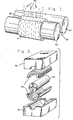
- FIGURE 1 illustrates the incorporation of chop-Red fibre strands into uncured rubber on a two roll rubber mill;
- FIGURE 21 is an exploded perspective view of the manufacture of a fibre reinforced rubber roller in a curing press using the fibre reinforced rubber mixed on the two roll mill of FIGURE 1;
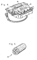
- FIGURE 3 is a perspective view of the completed fibre reinforced rubber roller made in the curing press of FIGURE 2; and
- FIGURE 4 shows the roller of FIGURE 3 mounted for operation in a motorised cargo roller assembly.
- Rubber is typically blended by a rubber manufacturer to meet the performance requirements of the purchaser, and is supplied to the purchaser in uncured rough slabs typically weighing 5-100 pounds. Rubber for use in aircraft cargo rollers must have good weather resistance, oil resistance, and abrasion and tear resistance, as well as being at least somewhat burn-resistant. The elastomer used for roller applications is generally synthetic rubber, such as neoprene, nitrile, or urethane.
- The rubber formulation includes other components often making up a substantial portion of the formulation. The rubber is formulated with the weight of the elastomer being designated as 100 parts, and the weight of other components being specified as percentage parts of the total weight of the elastomer used. Typically carbon black is added to give strength and a reinforcing effect to the compound, oil is added as an extender for the elastomer, and zinc oxide, stearic acid, and an accelerator are used to control the rate and degree of vulcanisation. Other components may be added to improve aging characteristics, reduce fatigue cracking, and to act to improve fire- retardant properties. The formulation of rubber for roller applications is thus well known in the art, and is done by rubber companies such as Goodyear, Firestone, and B. F. Goodrich.
- Since under the present invention chopped fibre strands are to be added to the rubber, which will act to increase the hardness of the rubber, the rubber formula should be specified to have a hardness less than the desired final hardness of the rubber roller. For example, while rubber rollers without fibre reinforcement typically have a hardness of between 70 and 75 on the ASTM D 2240 type A (hereinafter Type A) durometer scale, the rubber formula for use with chopped fibre strands may typically have a hardness of between 60 and 70 on. the Type A Scale in the preferred embodiment.
- As stated earlier, specially blended rubber is generally supplied in uncured slabs each weighing 5-100 pounds. The specially blended
rubber 10 is fed into a tworoll rubber mill 20 shown in FIGURE 1, having afaster steel roller 22 and aslower steel roller 24. Since therollers rubber formulation 10. As therubber 10 comes out of the bottom of the tworoll mill 20, it is taken by the operator and reinserted into the tworoll mill 20 between therollers rubber 10 around thefaster roller 22, as shown in FIGURE 1. Since the rubber slab is sized to have slightly more rubber than needed to make a band around thefaster roller 22, a portion of therubber 10 will pile up in arubber bank 30 atop and between therollers - As the
rubber 10 is run on the tworoll mill 20, it will increase in temperature and become more pliable, a step which must be followed before the fibre may be incorporated into the rubber. Typically, the operator may cut or slash therubber 10 around theroller 22, pull the rubber from the bottom of theroller 22 outwardly and reinsert it into the top of the tworoll mill 20. This process is called "cutting from side-to-side", is well known in the art, and in fact is used by rubber manufacturers to mix the rubber formulation. Another technique used by manufacturers to mix the rubber is "cross-milling", which consists of cutting the rubber around the roller, rilling it up, and reintroducing it to the two roll mill end first, thusly milling the rubber in a direction perpendicular to the original direction. Crossmilling and cutting from side-to-side both may be used before fibre is added to the rubber, when the rubber is mill freshened. - The chopped
fibre 40 to be incorporated into therubber 10 is an aromatic polyamide such as Kevlar or Nomex or a polyethylene terephthalate such as Dacron in the preferred embodiment, with a fibre length from 4.76mm to 12.7 millimetres (three-sixteenths of an inch to one-half inch), with the amount of fibre to be incorporated measured as a percentage of the elastomer in the rubber formula. The diameter of the fibre typically may be from 0.019mm (0.00075 inch) to 0.127mm (0.005 inch). Polyamides such as nylon can also be used for the fibres ascan natural fibres such as hemp or cotton. Kevlar, Nomex, or Dacron are preferred because of their superior fibre strength. Typically, from 0.5 to 3 parts of fibre per hundred parts of elastomer are used. - The length of the fibre must be at least 4.76mm (three-sixteenths of an inch) to provide sufficient reinforcement properties, and not greater than 12.7 mm (one-half inch) long since longer fibres are hard to blend in. The amount of fibre incorporated in the rubber formula must be sufficient to provide adequate reinforcement and yet is limited by the hardness of the resulting fibre-reinforced rubber. For example, for rubber formulas having a hardness of between 60 and 70 on the Type A Scale, if greater than 3 parts of fibre per 100 parts of elastomer are added, the hardness of the resulting fibre-reinforced rubber will be too high, resulting in the roller having a low surface coefficient of friction and a tendency to slip. Typically, a final hardness of 75 on the Type A Scale is the upper limit of hardness for rubber rollers in aircraft cargo bay applications.
- While the mill is running, the
fibre strands 40 are sprinkled by the operator of the tworoll mill 20 onto therubber bank 30 which has built up on thefaster roller 22. By then allowing the tworoll mill 20 to run and shear therubber 10, thefibres 40 will be dispersed in therubber 10 with a substantially parallel orientation which is circumferential around thefaster roll 22. It is very important to note that while cutting from side-to-side may be done after the fibre is added, cross- milling may not be done. The reason for not cross-milling is that if cross-milling is done after the fibre is added, the fibre orientation in the rubber will not be substantially parallel. - After the
fibre 40 is incorporated in therubber 10, the band ofrubber 10 may be slashed and removed from the tworoll mill 20. It may be noted that the thickness of therubber 10 which is determined by the tworoll mill 20, should be only slightly greater than the actual thickness needed for construction of the rubber roller. - The reinforced rubber is then cut into preformed
pads 50 as shown in FIGURE 2, each of which will extend halfway around the completed rubber roller. - A
metal roller hub 60 about which therubber pads 50 will be. placed may be coated with an adhesive to ensure that therubber pads 50 will adhere to thehub 60. Therubber pads 50 and thehub 60 are then placed into the curing mould having atop half portion 70 and abottom half portion 72, as shown in FIGURE 2. The curing mould uses a pressure varying from 4136.856 to 6894.76LPa (600 to 1000 psi), and a curing temperature of approximately 154°C (310°F) for about 35 minutes to cure the rubber. The completedrubber roller 80 shown in FIGURE 3, thus has a rubber covering with the fibres extending in a substantially circumferential orientation. - It is important to note that if the fibres in the
roller 80 are not substantially circumferentially oriented, theroller 80 will not have superior wear resistance. In fact, if non-oriented fibres are used one of two results is inevitable: either so much fibre is used to obtain a sufficient degree of wear resistance that the hardness of the roller is. so high that it will have virtually no gripping power at all, resulting in a totally useless roller, or there will be insufficient circumferential fibre orientation to increase wear resistance, resulting in a rubber roller which wears out too quickly. - The
rubber roller 80 may then be inserted into a typicalmotorised drive unit 90 as shown in FIGURE 4. Themotorised drive unit 90 is inserted into the cargo deck of the aircraft cargo bay, and theroller 80 may be operated either to load or unload cargo from the aircraft. It has been found that acargo roller 80 constructed according to the principles of the present invention provides a useful life which is greater than ten times the useful life of a rubber roller not containing oriented fibre reinforcement. This substantial increase in the useful life of therubber roller 80 is obtained at relatively minimal increased cost per roller, making the roller of the present invention a highly desirable product. - Thus, it may be appreciated that the
rubber roller 80 of the present invention presents the advantage of greatly increased wear resistance and a dramatically extended lifetime at a minimal cost increase, while still presenting desirable physical characteristics. Weather resistance, oil resistance, and non-inflammability characteristics of aroller 80 constructed according to the principles of the present invention are generally at least as good as non-reinforced rubber rollers, and also result in reduced maintenance and replacement time by the aircraft operator. The present invention is therefore a substantial improvement in the art, while affording virtually no drawbacks.
Claims (19)
Applications Claiming Priority (2)
| Application Number | Priority Date | Filing Date | Title |
|---|---|---|---|
| US537908 | 1983-09-30 | ||
| US06/537,908 US4766996A (en) | 1983-09-30 | 1983-09-30 | Rollers with oriented fiber reinforcement and method |
Publications (3)
| Publication Number | Publication Date |
|---|---|
| EP0136867A2 EP0136867A2 (en) | 1985-04-10 |
| EP0136867A3 EP0136867A3 (en) | 1987-06-03 |
| EP0136867B1 true EP0136867B1 (en) | 1989-02-08 |
Family
ID=24144610
Family Applications (1)
| Application Number | Title | Priority Date | Filing Date |
|---|---|---|---|
| EP84306401A Expired EP0136867B1 (en) | 1983-09-30 | 1984-09-19 | Rollers with oriented fibre reinforcement and method of making them |
Country Status (3)
| Country | Link |
|---|---|
| US (1) | US4766996A (en) |
| EP (1) | EP0136867B1 (en) |
| DE (1) | DE3476650D1 (en) |
Cited By (1)
| Publication number | Priority date | Publication date | Assignee | Title |
|---|---|---|---|---|
| DE10229539A1 (en) * | 2002-07-01 | 2004-01-29 | Telair International Gmbh | Roller drive unit |
Families Citing this family (18)
| Publication number | Priority date | Publication date | Assignee | Title |
|---|---|---|---|---|
| US5484362A (en) * | 1989-06-19 | 1996-01-16 | Life Fitness | Exercise treadmill |
| US6923746B1 (en) | 1989-06-19 | 2005-08-02 | Brunswick Corporation | Exercise treadmill |
| CA2018219C (en) * | 1989-06-19 | 1998-03-24 | Richard E. Skowronski | Exercise treadmill |
| US5142759A (en) * | 1991-08-27 | 1992-09-01 | Beloit Corporation | Roll cover apparatus |
| US5183150A (en) * | 1991-12-13 | 1993-02-02 | Allied-Signal Inc. | Cargo drive unit with a hysteresis coupling |
| DE4321163C3 (en) * | 1993-06-25 | 2000-07-13 | Freudenberg Carl Fa | Cross cutter |
| US5441468A (en) * | 1994-03-04 | 1995-08-15 | Quinton Instrument Company | Resiliently mounted treadmill deck |
| US5664499A (en) * | 1996-08-28 | 1997-09-09 | Kingsmill; William Gault | Ski lift loader and unloader |
| DE19851936B4 (en) * | 1998-11-11 | 2005-05-12 | Voith Sulzer Papiertechnik Patent Gmbh | Method for satinizing a paper or similar material web and roller for a calendering calender |
| DE19919569B4 (en) * | 1999-04-29 | 2011-07-07 | Voith Patent GmbH, 89522 | Elastic roller and method for producing such |
| DE19925421A1 (en) * | 1999-06-02 | 2000-12-07 | Voith Sulzer Papiertech Patent | Elastic roller and method of making it |
| DE29921170U1 (en) * | 1999-12-02 | 2000-02-24 | Schaefer Gmbh Fritz | Roll, especially plastic roll |
| US7771333B2 (en) * | 2001-02-06 | 2010-08-10 | Advanced Aircraft Roller Systems, Inc. | Conveyor roller system |
| US6461279B1 (en) | 2001-07-25 | 2002-10-08 | Hai Pin Kuo | Treadmill having dual treads for stepping exercises |
| JP4285299B2 (en) * | 2004-03-30 | 2009-06-24 | 住友ゴム工業株式会社 | Paper feed roller |
| WO2009131684A1 (en) * | 2008-04-22 | 2009-10-29 | John Dallum | Lightweight conveyor roller |
| SI25013A (en) | 2015-06-02 | 2016-12-30 | Roman Gumzej | Devices for quick boarding and disembarkment of planes |
| US10850843B2 (en) | 2018-05-03 | 2020-12-01 | Advanced Aircraft Roller Systems, Inc. | Roller assembly of a cargo loading system |
Family Cites Families (32)
| Publication number | Priority date | Publication date | Assignee | Title |
|---|---|---|---|---|
| CA513684A (en) * | 1955-06-14 | L. Luaces Enrique | Spinning cots | |
| US1903038A (en) * | 1929-12-10 | 1933-03-28 | Eijiro Yamamoto | Felt rubber roller |
| US2342556A (en) * | 1940-08-02 | 1944-02-22 | Dayton Rubber Mfg Co | Method of making endless members for use in drafting units |
| US2393953A (en) * | 1944-04-10 | 1946-02-05 | Dayton Rubber Mfg Co | Spinning cot for textile fiber processing |
| US2621141A (en) * | 1949-04-19 | 1952-12-09 | Pittsburgh Waterproof Company | Method of covering an ironing roll |
| US2804678A (en) * | 1953-09-30 | 1957-09-03 | Dayton Rubber Company | Roll |
| US2801461A (en) * | 1954-07-30 | 1957-08-06 | Kusters Eduard | Rolls for use in squeezing liquids from textiles and the like and a method of producing such rolls |
| FR1198567A (en) * | 1957-02-27 | 1959-12-08 | Freudenberg Carl Kg | Process for producing coatings of fibrous material impregnated with binders on cylinders |
| US3468997A (en) * | 1963-03-14 | 1969-09-23 | Beckman Instruments Inc | Method of making a high strength rotary member |
| US3232409A (en) * | 1964-03-13 | 1966-02-01 | Miner Machine Company | Conveyor intersection |
| FR1448278A (en) * | 1965-06-24 | 1966-08-05 | Saint Gobain | Improvement in the transport of glass sheets |
| US3460222A (en) * | 1966-12-30 | 1969-08-12 | Sw Ind Inc | Paper manufacturing roll constructions and processes |
| US3568286A (en) * | 1968-04-17 | 1971-03-09 | Grace W R & Co | Compressible roll |
| US3588978A (en) * | 1968-12-18 | 1971-06-29 | Beloit Corp | Grooved roll for paper-making |
| US3635158A (en) * | 1969-10-06 | 1972-01-18 | William D Budinger | Roller for printing press |
| US3707752A (en) * | 1970-10-28 | 1973-01-02 | Beloit Corp | Roll covering |
| US3710469A (en) * | 1970-11-04 | 1973-01-16 | N Kitazawa | Oiling roller |
| DE2057644A1 (en) * | 1970-11-24 | 1972-05-31 | Clouth Gummiwerke Ag | Improving adhesion to epdm compsn to metal substrate - using an epdm polychlorobutadiene blend as intermediate binder layer |
| US3741504A (en) * | 1971-05-06 | 1973-06-26 | Boeing Co | Cargo handling system |
| JPS4877247A (en) * | 1972-01-24 | 1973-10-17 | ||
| US3800381A (en) * | 1972-06-19 | 1974-04-02 | Beloit Corp | Covered roll for paper making |
| US3815197A (en) * | 1972-11-08 | 1974-06-11 | Hudson Corp | Glass lehr roll and method of manufacture |
| US3852862A (en) * | 1972-11-08 | 1974-12-10 | New Hudson Corp | Roll and method of manufacture |
| FR2242874A7 (en) * | 1973-08-10 | 1975-03-28 | Kleber Colombes | Roller for frictionally driving conveyor belts - with rubber cover contg short fibres oriented parallel to rolling axis |
| JPS6012688B2 (en) * | 1977-07-11 | 1985-04-03 | 富士写真フイルム株式会社 | Super calender elastic roll for magnetic tape |
| US4203509A (en) * | 1978-06-23 | 1980-05-20 | Textron, Inc. | Cargo roller |
| US4244781A (en) * | 1979-06-11 | 1981-01-13 | Nicolet, Inc. | Non-asbestos millboard composition |
| JPS5936133B2 (en) * | 1979-08-10 | 1984-09-01 | 山内ゴム工業株式会社 | Polyurethane rubber roll and its manufacturing method |
| JPS56130802A (en) * | 1980-03-18 | 1981-10-14 | Pioneer Electronic Corp | Tone arm constituent |
| US4389361A (en) * | 1980-11-13 | 1983-06-21 | The B. F. Goodrich Company | Process for molding fiber loaded rubber compound |
| JPS5871147A (en) * | 1981-10-26 | 1983-04-27 | Ricoh Co Ltd | Manufacture of silicon rubber roll |
| US4470498A (en) * | 1982-04-05 | 1984-09-11 | Board Of Control Of Michigan Technological University | Apparatus for making continuous lengths of composite wood material, the apparatus including rotating circular baffles |
-
1983
- 1983-09-30 US US06/537,908 patent/US4766996A/en not_active Expired - Lifetime
-
1984
- 1984-09-19 EP EP84306401A patent/EP0136867B1/en not_active Expired
- 1984-09-19 DE DE8484306401T patent/DE3476650D1/en not_active Expired
Cited By (2)
| Publication number | Priority date | Publication date | Assignee | Title |
|---|---|---|---|---|
| DE10229539A1 (en) * | 2002-07-01 | 2004-01-29 | Telair International Gmbh | Roller drive unit |
| DE10229539B4 (en) * | 2002-07-01 | 2005-09-01 | Telair International Gmbh | Roller drive unit |
Also Published As
| Publication number | Publication date |
|---|---|
| US4766996A (en) | 1988-08-30 |
| EP0136867A2 (en) | 1985-04-10 |
| DE3476650D1 (en) | 1989-03-16 |
| EP0136867A3 (en) | 1987-06-03 |
Similar Documents
| Publication | Publication Date | Title |
|---|---|---|
| EP0136867B1 (en) | Rollers with oriented fibre reinforcement and method of making them | |
| EP0105822B1 (en) | Tread | |
| EP0646524B1 (en) | Polyurethane deicer | |
| EP1201414B1 (en) | Method of manufacturing the sidewall of a pneumatic tire | |
| AU593070B2 (en) | Reinforced composite structure | |
| EP0924108B1 (en) | Heavy duty pneumatic radial tires | |
| EP0857887B1 (en) | A power transmission belt | |
| JPH01153305A (en) | Radial tire | |
| CA1116441A (en) | Adjustless v-belt and method of manufacture | |
| EP0129255B1 (en) | Power transmission belt manufacture | |
| US4844561A (en) | Composite tread for track-laying vehicles | |
| GB2058284A (en) | Elastomeric bearings with dual stock layers | |
| US20100101693A1 (en) | Method for introducing hard materials into a tire running tread | |
| CA2180413A1 (en) | Abrasion resistant plastic bonded to a diaphragm | |
| EP0697969B1 (en) | Wearing surface for tyres for winter conditions | |
| EP0200055A2 (en) | Tire band structure | |
| EP0898076A1 (en) | Abrasion resistant plastic bonded to a diaphragm | |
| EP0612383A1 (en) | Brakes. | |
| CN113968996B (en) | Wear-resistant hydrophobic low-rolling-resistance conveyor belt cover rubber and preparation method thereof | |
| GB2261480A (en) | Construction of brake elements | |
| WO2007085324A1 (en) | Conveyor belt with non-stick coating | |
| US4323102A (en) | Dirt seal for removable rubber belts | |
| EP0542357B1 (en) | Brake element comprising linings secured to backing plates | |
| US3741837A (en) | Method of producing vulcanizable sheet material with multifilament glass cord | |
| JP5670143B2 (en) | Solid tire |
Legal Events
| Date | Code | Title | Description |
|---|---|---|---|
| PUAI | Public reference made under article 153(3) epc to a published international application that has entered the european phase |
Free format text: ORIGINAL CODE: 0009012 |
|
| AK | Designated contracting states |
Designated state(s): DE FR GB IT |
|
| PUAL | Search report despatched |
Free format text: ORIGINAL CODE: 0009013 |
|
| AK | Designated contracting states |
Kind code of ref document: A3 Designated state(s): DE FR GB IT |
|
| 17P | Request for examination filed |
Effective date: 19870928 |
|
| 17Q | First examination report despatched |
Effective date: 19880420 |
|
| RAP1 | Party data changed (applicant data changed or rights of an application transferred) |
Owner name: ALLIED-SIGNAL INC. |
|
| ITF | It: translation for a ep patent filed |
Owner name: BARZANO' E ZANARDO ROMA S.P.A. |
|
| GRAA | (expected) grant |
Free format text: ORIGINAL CODE: 0009210 |
|
| AK | Designated contracting states |
Kind code of ref document: B1 Designated state(s): DE FR GB IT |
|
| REF | Corresponds to: |
Ref document number: 3476650 Country of ref document: DE Date of ref document: 19890316 |
|
| ET | Fr: translation filed | ||
| PLBE | No opposition filed within time limit |
Free format text: ORIGINAL CODE: 0009261 |
|
| STAA | Information on the status of an ep patent application or granted ep patent |
Free format text: STATUS: NO OPPOSITION FILED WITHIN TIME LIMIT |
|
| 26N | No opposition filed | ||
| ITTA | It: last paid annual fee | ||
| PGFP | Annual fee paid to national office [announced via postgrant information from national office to epo] |
Ref country code: GB Payment date: 19940909 Year of fee payment: 11 Ref country code: FR Payment date: 19940909 Year of fee payment: 11 |
|
| PGFP | Annual fee paid to national office [announced via postgrant information from national office to epo] |
Ref country code: DE Payment date: 19940921 Year of fee payment: 11 |
|
| PG25 | Lapsed in a contracting state [announced via postgrant information from national office to epo] |
Ref country code: GB Effective date: 19950919 |
|
| GBPC | Gb: european patent ceased through non-payment of renewal fee |
Effective date: 19950919 |
|
| PG25 | Lapsed in a contracting state [announced via postgrant information from national office to epo] |
Ref country code: FR Effective date: 19960531 |
|
| PG25 | Lapsed in a contracting state [announced via postgrant information from national office to epo] |
Ref country code: DE Effective date: 19960601 |
|
| REG | Reference to a national code |
Ref country code: FR Ref legal event code: ST |