EP0136488A2 - Rocking switch actuator for a low force membrane contact switch - Google Patents
Rocking switch actuator for a low force membrane contact switch Download PDFInfo
- Publication number
- EP0136488A2 EP0136488A2 EP84109529A EP84109529A EP0136488A2 EP 0136488 A2 EP0136488 A2 EP 0136488A2 EP 84109529 A EP84109529 A EP 84109529A EP 84109529 A EP84109529 A EP 84109529A EP 0136488 A2 EP0136488 A2 EP 0136488A2
- Authority
- EP
- European Patent Office
- Prior art keywords
- actuator
- contact switch
- key
- spring
- rocking
- Prior art date
- Legal status (The legal status is an assumption and is not a legal conclusion. Google has not performed a legal analysis and makes no representation as to the accuracy of the status listed.)
- Granted
Links
Images


Classifications
-
- H—ELECTRICITY
- H01—ELECTRIC ELEMENTS
- H01H—ELECTRIC SWITCHES; RELAYS; SELECTORS; EMERGENCY PROTECTIVE DEVICES
- H01H13/00—Switches having rectilinearly-movable operating part or parts adapted for pushing or pulling in one direction only, e.g. push-button switch
- H01H13/70—Switches having rectilinearly-movable operating part or parts adapted for pushing or pulling in one direction only, e.g. push-button switch having a plurality of operating members associated with different sets of contacts, e.g. keyboard
- H01H13/702—Switches having rectilinearly-movable operating part or parts adapted for pushing or pulling in one direction only, e.g. push-button switch having a plurality of operating members associated with different sets of contacts, e.g. keyboard with contacts carried by or formed from layers in a multilayer structure, e.g. membrane switches
- H01H13/705—Switches having rectilinearly-movable operating part or parts adapted for pushing or pulling in one direction only, e.g. push-button switch having a plurality of operating members associated with different sets of contacts, e.g. keyboard with contacts carried by or formed from layers in a multilayer structure, e.g. membrane switches characterised by construction, mounting or arrangement of operating parts, e.g. push-buttons or keys
-
- H—ELECTRICITY
- H01—ELECTRIC ELEMENTS
- H01H—ELECTRIC SWITCHES; RELAYS; SELECTORS; EMERGENCY PROTECTIVE DEVICES
- H01H13/00—Switches having rectilinearly-movable operating part or parts adapted for pushing or pulling in one direction only, e.g. push-button switch
- H01H13/02—Details
- H01H13/26—Snap-action arrangements depending upon deformation of elastic members
- H01H13/28—Snap-action arrangements depending upon deformation of elastic members using compression or extension of coil springs
-
- H—ELECTRICITY
- H01—ELECTRIC ELEMENTS
- H01H—ELECTRIC SWITCHES; RELAYS; SELECTORS; EMERGENCY PROTECTIVE DEVICES
- H01H2235/00—Springs
- H01H2235/012—Euler spring
Abstract
Description
- This invention relates to a rocking switch actuator and, more particularly, to a rocking switch actuator for a membrane contact switch in which actuation is by depression of a key.
- In EP-0,001,031, there is shown a pivoting switch actuator using a buckling compression spring to move the actuator in response to depression of a key whereby the actuator causes closing and opening of a switch through changing the capacitance between contacts with which the actuator cooperates. The actuator of the aforesaid patent pivots about a single pivot point when a key is depressed.
- The present invention is an improvement of the aforesaid patent in that the actuator of the present invention is designed so that it produces a force at least double the membrane force to close a contact switch of a membrane contact switch assembly with which the actuator cooperates. The present invention accomplishes this through transmitting substantially all of the force applied to the key to activate the contact switch of the membrane contact switch assembly.
- The actuator for opening and closing the contact switch of the membrane contact switch assembly pivots about a first pivot point during depression of a key as the spring is catastrophically buckled in a selected direction. When the spring has catastrophically buckled, the rocking actuator is rotated about a second pivot point with the second pivot point being located substantially vertically above the contact switch to be closed. This enables substantially all of the force from the depressed key to be applied at the second pivot point to close the contact switch. Thus, substantially the entire force of the key is transferred, when the spring is buckled, to close the contact switch.
- The rocking actuator of the present invention also avoids any undesired opening and closing of the contact switch when the key is released. This undesired opening and closing of the contact switch is avoided because the moment produced by buckling of the spring does not decrease as fast as compression of the spring when the depressed key is released whereby the actuator initially rotates further in the direction in which it rotated during depression of the key prior to rotation in the opposite direction to return the actuator to its initial rest position.
- An object of this invention is to provide a switch actuator for a full travel tactile membrane keyboard.
- Another object of this invention is to provide a switch actuator for a contact switch of a membrane contact switch assembly.
- A further object of this invention is to provide a switch actuator having minimum bounce of the switch actuator during release of the switch actuator from the position in which it activated a contact switch.
- Still another objects of this invention is to control both the force required to close a contact switch of a membrane contact switch assembly and the force applied to close the contact switch.
- The foregoing and other objects, features, and advantages of the invention will be apparent from the following more particular description of the preferred embodiment of the invention as illustrated in the accompanying drawings.
- In the drawings :
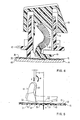
- Fig. 1 is an enlarged end elevational view of a rocking actuator of the present invention in its rest position with a portion of a membrane contact switch assembly shown in section and showing the force and moment acting on the actuator from a buckling spring.
- Fig. 2 is an enlarged sectional view of a key, its support, the actuator, and the membrane contact switch assembly with the key being in an inactivated position so that the actuator is in its rest position of Fig. 1.
- Fig. 3 is a view, similar to Fig. 1, but showing the actuator in its actuation position for closing a contact switch of the membrane contact switch assembly.
- Fig. 4 is a view, similar to Fig. 2, but corresponding to the position of the actuator in Fig. 3.
- Fig. 5 is a view, similar to Figs. 1 and 3, but showing the actuator in its position just prior to opening of the contact switch.
- Fig. 6 is a view, similar to Figs. 2 and 4, but corresponding to the position of the actuator in Fig. 5.
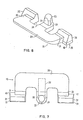
- Fig. 7 is an enlarged plan view of the rocking switch actuator of the present invention.
- Fig. 8 is an enlarged isometric view of the rocking switch actuator of the present invention.
- Fig. 9 is a graph illustrating the key force and its travel along with showing the position of the rocking actuator at certain positions of the key travel.
- Referring to the drawings and particularly Fig. 2, there is shown a
key 10 of a keyboard of the type shown and described in EP-A-0,095,023. Thekey 10 is employed to select one of the characters of a typewriter, for example. - The
key 10 is slidably mounted on an upstanding hollowcylindrical support 11 of aframe 12. Theframe 12 has one of the upstanding hollowcylindrical supports 11 for each of the keys 10 (one shown) of the keyboard. - The
frame 12, which is formed of a suitable plastic as is thekey 10, is attached to ametal base plate 14, which is supported by the typewriter frame. Theframe 12 is attached to thebase plate 14 by any suitable means. Theframe 12 preferably is attached to thebase plate 14 by forming theframe 12 with stepped tenons with each of the tenons extending through an opening (not shown) in themetal base plate 14 after initially passing through a larger opening (not shown) in a membranecontact switch assembly 15, which rests on the upper surface of thebase plate 14. The larger portion of the stepped tenon has a shoulder at its junction with the smaller portion passing through the opening in thebase plate 14 so that the shoulder rests on the upper surface on thebase plate 14. The tenon is heated to form a rivet type engagement with the bottom surface of thebase plate 14. - The
key 10 includes a downwardly extendingstem 16 extending inside of the upstanding hollowcylindrical support 11 of theframe 12 and being slidably supported thereby. The exterior of thestem 16, which is bifurcated to have two separate skirts 17 (one shown), and the interior of the upstanding hollowcylindrical support 11 have cooperating ribs and slots to orient thekey 10 and to guide thekey 10 during its vertical motion when it is depressed by a user and then released. - A
spring 18 extends between thekey 10 and a pivoting rockingactuator 19, which causes closure of acontact switch 20 of the membranecontact switch assembly 15 when thekey 10 is depressed. Thespring 18 has its upper end acting against amounting base 21 in thestem 16 of thekey 10. Themounting base 21 is angled slightly to set the initial deflection of thespring 18 in a selected direction (to the right in Fig. 2). This is towards the front of the typewriter as aninclined surface 22 of thekey 10 is the front surface of thekey 10. Any sideways buckling of thespring 18 is limited by theskirts 17 of thestem 16 of thekey 10. - The
spring 18 has its lower end surround anupstanding post 23 of the pivoting rockingactuator 19 and is attached thereto by a press fit. Thepost 23 has flat faces 24 (see Fig. 8) to aid in easier press fitting of the spring 18 (see Fig. 2) on thepost 23. - The
spring 18 continuously urges the key 10 upwardly since the pivoting rockingactuator 19 always is resting onupper surface 25 of the membranecontact switch assembly 15. The upward movement of thekey 10 is limited by a stop 26 (one shown) on the outer surface of each of theskirts 17 of thestem 16 of thekey 10 adjacent the bottom of theskirt 17 engaging a shoulder 27 (one shown) on the inner surface of the upstandinghollow support 11 of theframe 12. Each of thestops 26 includes a slanted surface cooperating with a slanted surface on thecooperating shoulder 27 to enable each of thestops 26 to be forced beneath thecooperating shoulder 27 when thekey 10 is inserted within the upstanding hollowcylindrical support 11 of theframe 12 during assembly or during replacement of thekey 10. - The
post 23 of therocking actuator 19 extends upwardly from a finger 28 (see Fig. 8), which extends from abase 29 of theactuator 19. Thefinger 28 is intermediate twoend fingers actuator 19 extending from opposite ends of thebase 29. - The
actuator 19 is formed with thefingers stem 16 of thekey 10 to enter the space between the fingers 28 (see Fig. 8) and 30 and the other of the skirts 17 (see Fig. 2) to enter the space between the fingers 28 (see Fig. 8) and 31 so that theskirts 17 of thestem 16 of thekey 10 can move downwardly relative to theactuator 19 from the position of Fig. 2 to the position of Fig. 4. - The finger 30 (see Fig. 8) has a pad or
foot 32 at its end, and thefinger 31 has a pad orfoot 33 at its end. Thepost 23 is disposed substantially perpendicular tobottom surface 34 of thepad 32 and tobottom surface 35 of thepad 33. Thebottom surface 34 of thepad 32 and thebottom surface 35 of thepad 33 are disposed in the same plane. - The
actuator 19 has a downwardly extending portion or protusion 36 (see Figs. 1 and 7) extending downwardly from the bottom surface of a portion of thefinger 28 and a portion of thebase 29. The downwardly extendingportion 36 preferably has a curved bottom surface 37 (see Fig. 1) for its entire periphery. Thus, the downwardly extendingportion 36 has itsbottom surface 37 curved from the finger 28 (see Fig. 7) to thebase 29 in the plane of Fig. 1 (This is from front to back, not normal to the view). - When the
actuator 19 is in the rest position of Figs. 1 and 2 in which thekey 10 has not been depressed but is urged to its uppermost position by thespring 18, theactuator 19 has the bottom surface 34 (see Fig. 8) of thepad 32 and thebottom surface 35 of thepad 33 as its sole bottom surface in contact with the upper surface 25 (see Fig. 1) of the membranecontact switch assembly 15. The bottom surface 34 (see Fig. 8) of thepad 32 and thebottom surface 35 of thepad 33 are offset from the contact switch 20 (see Fig. 1) so that thespring 18, even though compressed, is not exerting any force on thecontact switch 20 when theactuator 19 is in its rest position. In this rest position, thecurved surface 37 of the downwardly extendingportion 36 of theactuator 19 is slightly spaced from theupper surface 25 of the membranecontact switch assembly 15. This slight spacing is about 0.02 millimeters. - The membrane
contact switch assembly 15 is formed in the manner more particularly shown and described in the aforesaid European patent application. The membranecontact switch assembly 15 includes anupper layer 38 of an electrically insulating material, anintermediate layer 39 of an electrically insulating material, and alower layer 40 of an electrically insulating material. Each of the layers 38-40 is preferably formed of polyethylene terephtalate. The layers 38-40 are retained in engagement with each other by a suitable glue. - The
layer 38 of electrically insulating material has circular contacts 41 (one shown) formed on itsbottom surface 42 as shown and described in the aforesaid European patent application. Thelayer 40 has circular contacts 43 (one shown) formed on its upper surface 44 as shown and described in the aforesaid European patent application. Thecontacts - The
intermediate layer 39 of electrically insulating material has acircular opening 45, which is larger than each of thecontacts contacts contact switch 20. Thus, when thelayer 38 is moved downwardly by theactuator 19 into theopening 45 in thelayer 39 of electrically insulating material, thecontact switch 20 closes because thecontact 41 is moved into engagement with thecontact 43 as shown in Figs. 3 and 4. - When the
actuator 19 is in its rest position of Figs. 1 and 2, theactuator 19 has thebottom surface 34 of thepad 32 and the bottom surface 35 (see Figs. 7 and 8) of thepad 33 as its sole bottom surface engaging the upper surface 25 (see Fig. 1) of the membranecontact switch assembly 15. This is because a force F, which represents the compression force exerted by the spring 18 (see Fig. 2) on theactuator 19, produces a moment, which is the product of the force F (see Fig. 1) and a distance x from the center of thepost 23 to forwardedge 47 of thebottom surface 34 of thepad 32 and forward edge 48 (see Fig. 7) of thebottom surface 35 of thepad 33, greater than a moment M, which is produced by the slight initial buckling of the spring 18 (see Fig. 2). As previously mentioned, thespring 18 is buckled in the selected direction when the key 10 is in its unactuated position. - The forward edges 47 and 48 (see Fig. 7) constitute an initial pivot point or axis about which the actuator 19 (see Fig. 1) rotates clockwise (as viewed in Fig. 1) when the moment M becomes greater than the product of F and x. At the rest position of the
actuator 19, the moment M is smaller than the moment produced by the product of F and x as previously mentioned. In the rest position, thecurved bottom surface 37 of the downwardly projectingportion 36 is slightly spaced from theupper surface 25 of the membranecontact switch assembly 15 as shown in Fig. 1. - When the key 10 is depressed from the position of Fig. 2 to the position of Fig. 4, the force exerted on the key 10 increases the force F (see Fig. 3) transmitted by the spring 18 (see Fig. 4) to the
actuator 19. The force produced on the key 10 during its depression is illustrated with respect to the displacement of the key 10 in Fig. 9. - While the force F is increased as shown in Fig. 3 from the force F at the rest position of the
actuator 19 as shown in Fig. 1 due to depression of the key 10 (see Fig. 4), the moment M (see Fig. 3), which is produced by increased buckling of thespring 18 from the position of Fig. 2 to the position of Fig. 4 due to thespring 18 catastrophically buckling, is larger than the moment produced by the product of the force F (see Fig. 3) and the distance x. As a result, theactuator 19 pivots about the initial pivot point or axis, which is defined by theedge 47 of thebottom surface 34 of thepad 32 and the edge 48 (see Fig. 7) of thebottom surface 35 of thepad 33 of theactuator 19. This clockwise (as viewed in Figs. 1 and 3) rotation of theactuator 19 causes thecurved surface 37 of the downwardly extendingportion 36 of theactuator 19 to engage theupper surface 25 of the membranecontact switch assembly 15 to move theupper layer 38 of electrically insulating material downwardly into theopening 45 of theintermediate layer 39 of electrically insulating material so that thecontact 41 on thebottom surface 42 of thelayer 38 of electrically insulating material engages thecontact 43 on the upper surface 44 of thelayer 40 of electrically insulating material. - When the
actuator 19 rotates clockwise about the initial pivot point, thecurved surface 37 of the downwardly extendingportion 36 of theactuator 19 makes contact at a point 49 (see Fig. 3) with theupper layer 38 of electrically insulating material of the membranecontact switch assembly 15. The point 49 is indicated in Fig. 3 as being a distance d from the initial pivot point. When theactuator 19 is in the position of Fig. 3, the moment M is being opposed by a moment comprising the product of the force F and the total distance of x and d. At this time, the moment M is slightly greater than F (x + d). - since the only point of contact of the
actuator 19 with the membranecontact switch assembly 15 is at the point 49, the force F is equal to a resultant force R which is at the point 49. This a summing of the vertical forces acting on theactuator 19. - This means that substantially all of the downward force exerted on the key 10 (see Fig. 4) is transmitted to the membrane
switch contact assembly 15. This relatively high force reduces bounce of theactuator 19 and causes closing of thecontact switch 20. - The force F (see Fig. 3) produced by depression of the key 10 (see Fig. 4) is between 0,40 and 0,50 N when the
actuator 19 is engaging the membranecontact switch assembly 15 at the point 49 (see Fig. 3). The force to close thecontact switch 20 is about 0,15 N. Thus, the closing force exerted by theactuator 19 is at least twice the force required to close thecontact switch 20 of the membranecontact switch assembly 15. - The force required to close the
contact switch 20 is dependent upon the material of theupper layer 38 of electrically insulating material, its thickness, the size of theopening 45 in theintermediate layer 39 of electrically insulating material, and the depth of theopening 45 in theintermediate layer 39 of electrically insulating material. These are selected so that the force required to close thecontact switch 20 will be less than one-half of the resultant force R acting at the point 49. - When the
contact switch 20 is closed, the user feels this due to the catastrophic buckling of the spring 18 (see Fig. 4) and then releases the key 10. However, even if the user continues to depress the key 10, maximum depression of the key 10 is limited by engagement of asurface 50 of the key 10 with anupper end 51 of the upstanding hollowcylindrical support 11. - When the key 10 is released, the force F (see Fig. 5) initially decreases faster than the moment M. As a result, the moment M is still greater than F (x + d) so that the
actuator 19 continues to rotate clockwise to maintain continuous closing of thecontact switch 20 while thebottom surface 34 of thepad 32 and the bottom surface 35 (see Fig. 8) of thepad 33 are raised further from the upper surface 25 (see Fig. 5) of the membranecontact switch assembly 15. This results in a point ofcontact 52 occurring between thecurved bottom surface 37 of the downwardly extendingportion 36 of theactuator 19 and theupper layer 38 of the electrically insulating material of the membranecontact switch assembly 15. - As can be observed by comparing Figs, 3 and 5, the distance d increases. Eventually, the moment M decreases because of unbuckling of the spring 18 (see Fig. 6) as the released key 10 moves upwardly under the force of the
spring 18. This plus the increase in the distance d results in theactuator 19 rotating counterclockwise (as viewed in Fig. 5) to return from the position of Fig. 5 to the rest position of Fig. 1. However, because of the further location of the point 52 (see Fig. 5) from the initial pivot point, which is defined by theforward edge 47 of thebottom surface 34 of thepad 32 and the forward edge 48 (see Fig. 8) of thebottom surface 35 of thepad 33, there is not any undesired opening and closing of thecontact switch 20. The rocking or rolling of the actuator 19 from the point 52 (see Fig. 5) to the left enables thebottom surface 34 of thepad 32 and the bottom surface 35 (see Fig. 8) of thepad 33 to return into engagement with theupper surface 25 of the membranecontact switch assembly 15 without any excessive bounce. This is avoided by thebottom surface 37 of the downwardly extendingportion 36 of theactuator 19 being curved. - Fig. 9 discloses the relation of the force of the key 10 (see Fig. 2) relative to its travel through an entire cycle. The position of the
actuator 19 at certain times also is indicated in this view. - Thus,
point 53 represents the position of the key 10 when theactuator 19 is in the position of Figs. 1 and 2 in which there has been no depression of the key 10 (see Fig. 1).Point 54 indicates the position of the key 10 when theactuator 19 is in the position of Figs. 3 and 4. The position of the key 10 when theactuator 19 is in the position of Figs. 5 and 6 is indicated atpoint 55. The position of the key 10 when it has returned to its initial position and theactuator 19 is in the position of Figs. 1 and 2 is indicated by apoint 56.Points - While the bottom surface 37 (see Fig. 1) of the downwardly extending
portion 36 of theactuator 19 has been shown as being a continuous curve along its entire periphery, it should be understood that a small portion of thebottom surface 37 could be flat if desired. This would be the portion of thebottom surface 37 of the downwardly extendingportion 36 of theactuator 19 engaging theupper surface 25 of the membranecontact switch assembly 15 during movement of the actuator 19 from the position of Fig. 3 to the position of Fig. 5. - In the same manner as discussed relative to EP-0,001,031, there is no possibility of teasing. That is, the key 10 (see Fig. 2) cannot be moved a small amount to cause opening and closing of the
contact switch 20 without it being felt by the user. - This is observed from Fig. 9 in which the physical hysteresis, which is of importance in creating the non-teasability, exists in the structure since the actuator 19 (see Fig. 2) does not snap back over center until a point below that at which snap over occurred is reached. That is, the point 54 (see Fig. 9) is when there is closing of the contact switch 20 (see Fig. 2) but it does not open until after the hysteresis has been passed during the return of the key 10 (see Fig. 2) to its initial unactuated position.
- As an example of relative dimensions, the
layer 38 of electrically insulating material may be 0.,076 mm, thelayer 39 of electrically insulating material may be 0,127 mm, and thelayer 40 of electrically insulating material may be 0,203 mm. Thebase plate 14 would have a thickness of about 1,27 mm. The radius of curvature of thecurved bottom surface 37 of the downwardly extendingportion 36 of theactuator 19 would be 7 mm. As previously mentioned, the space in Fig. 1 from thecurved bottom surface 37 of the downwardly projectingportion 36 of theactuator 19 to theupper surface 25 of the membranecontact switch assembly 15 is about 0.02 mm. These dimensions are to illustrate the relative sizes of parts, which have not necessarily been shown to scale in the drawings because of the substantial variation in sizes. - An advantage of this invention is that it produces a relatively high force for actuating a membrane switch. Another advantage of this invention is that it efficiently transmits the force from depression of a key of a keyboard to a force to close a contact switch of a membrane contact switch assembly. A further advantage of this invention is that it minimizes switch bounce during both actuation and release.
Claims (7)
Applications Claiming Priority (2)
| Application Number | Priority Date | Filing Date | Title |
|---|---|---|---|
| US538728 | 1983-10-03 | ||
| US06/538,728 US4528431A (en) | 1983-10-03 | 1983-10-03 | Rocking switch actuator for a low force membrane contact switch |
Publications (3)
| Publication Number | Publication Date |
|---|---|
| EP0136488A2 true EP0136488A2 (en) | 1985-04-10 |
| EP0136488A3 EP0136488A3 (en) | 1986-10-01 |
| EP0136488B1 EP0136488B1 (en) | 1988-11-02 |
Family
ID=24148167
Family Applications (1)
| Application Number | Title | Priority Date | Filing Date |
|---|---|---|---|
| EP84109529A Expired EP0136488B1 (en) | 1983-10-03 | 1984-08-10 | Rocking switch actuator for a low force membrane contact switch |
Country Status (5)
| Country | Link |
|---|---|
| US (1) | US4528431A (en) |
| EP (1) | EP0136488B1 (en) |
| JP (1) | JPS6081719A (en) |
| BR (1) | BR8404952A (en) |
| DE (1) | DE3475025D1 (en) |
Cited By (1)
| Publication number | Priority date | Publication date | Assignee | Title |
|---|---|---|---|---|
| GB2282703A (en) * | 1993-10-05 | 1995-04-12 | Daw Shen Chen | Mechanical key switch |
Families Citing this family (21)
| Publication number | Priority date | Publication date | Assignee | Title |
|---|---|---|---|---|
| JPS63111730U (en) * | 1987-01-13 | 1988-07-18 | ||
| US4859820A (en) * | 1988-03-31 | 1989-08-22 | American Telephone And Telegraph Company | Quiet key switch |
| JPH0624106Y2 (en) * | 1988-07-11 | 1994-06-22 | アルプス電気株式会社 | Push button switch |
| US5173578A (en) * | 1988-11-18 | 1992-12-22 | Matsushita Electric Industrial Co., Ltd. | Push button switch assembly |
| JPH0280929U (en) * | 1988-12-12 | 1990-06-21 | ||
| US4931606A (en) * | 1989-04-28 | 1990-06-05 | International Business Machines Corporation | Key switch mechanism and membrane actuator |
| EP0407012B1 (en) * | 1989-07-05 | 1995-10-25 | Acer Incorporated | Membrane switch assembly |
| US5057657A (en) * | 1990-07-23 | 1991-10-15 | Vedran Skulic | Electrical switch actuator mechanism |
| US5228561A (en) * | 1991-04-01 | 1993-07-20 | Hewlett-Packard Company | Long traveling button switch with enhanced user feedback |
| US5326951A (en) * | 1992-01-23 | 1994-07-05 | Alps Electric Co., Ltd. | Push button switch |
| DE19628753C2 (en) * | 1996-07-17 | 2003-02-20 | Abb Patent Gmbh | Electrical switching device |
| US6570106B1 (en) | 2000-07-10 | 2003-05-27 | Steven L. Merrick | Movable electric switches that move to reveal underlying control areas |
| US6740832B2 (en) * | 2002-03-27 | 2004-05-25 | 3M Innovative Properties Company | Apparatus exhibiting tactile feel |
| US6930269B1 (en) | 2004-06-28 | 2005-08-16 | Eaton Corporation | Quiet, medium current rocker switch |
| US7026565B1 (en) | 2004-12-27 | 2006-04-11 | Eaton Corporation | Self-contained actuator subassembly for a rocker switch and rocker switch employing the same |
| US7105762B1 (en) | 2005-06-07 | 2006-09-12 | Eaton Corporation | Rocker switch and actuator therefor |
| ATE456146T1 (en) * | 2006-12-28 | 2010-02-15 | Defond Components Ltd | ELECTRICAL SWITCH |
| US7952044B2 (en) * | 2008-11-26 | 2011-05-31 | Eaton Corporation | Rocker switch and actuator subassembly therefor |
| JP5891355B2 (en) * | 2012-02-03 | 2016-03-23 | パナソニックIpマネジメント株式会社 | Push switch |
| US20140209601A1 (en) * | 2013-01-30 | 2014-07-31 | Agm Container Controls, Inc. | Breather Valve Assemblies |
| CA2913671A1 (en) * | 2015-12-02 | 2017-06-02 | Pat S. Hao | Thin keyswitch, keyboard and keyboard overlay |
Citations (1)
| Publication number | Priority date | Publication date | Assignee | Title |
|---|---|---|---|---|
| EP0001031A1 (en) * | 1977-08-30 | 1979-03-07 | International Business Machines Corporation | Push button switch with snap action |
Family Cites Families (4)
| Publication number | Priority date | Publication date | Assignee | Title |
|---|---|---|---|---|
| US3982081A (en) * | 1974-09-04 | 1976-09-21 | Amp Incorporated | Keyboard assembly with overlapped flexible printed circuit cable switch |
| FR2501410A2 (en) * | 1981-01-12 | 1982-09-10 | Oreor Electronique | Control keyboard with extended key stroke and exchangeable key top - has spring or bellows between key-top and hinged actuator to damp excess key pressure |
| DE8113363U1 (en) * | 1981-05-07 | 1981-09-17 | Standard Elektrik Lorenz Ag, 7000 Stuttgart | Telephone set with dialing set |
| US4479040A (en) * | 1983-03-07 | 1984-10-23 | Oak Industries Inc. | Tactile feel switch with positive switch actuation |
-
1983
- 1983-10-03 US US06/538,728 patent/US4528431A/en not_active Expired - Fee Related
-
1984
- 1984-08-10 DE DE8484109529T patent/DE3475025D1/en not_active Expired
- 1984-08-10 EP EP84109529A patent/EP0136488B1/en not_active Expired
- 1984-08-20 JP JP59171662A patent/JPS6081719A/en active Granted
- 1984-10-02 BR BR8404952A patent/BR8404952A/en not_active IP Right Cessation
Patent Citations (1)
| Publication number | Priority date | Publication date | Assignee | Title |
|---|---|---|---|---|
| EP0001031A1 (en) * | 1977-08-30 | 1979-03-07 | International Business Machines Corporation | Push button switch with snap action |
Non-Patent Citations (2)
| Title |
|---|
| IBM TECHNICAL DISCLOSURE BULLETIN, vol. 21, no. 9, February 1979, pages 3727-3728, New York, US; R.H. HARRIS: "Buckling-spring key actuator with two-force pretravel" * |
| IBM TECHNICAL DISCLOSURE BULLETIN, vol. 26, no. 2, July 1983, page 709, New York, US; R.D. MURPHY: "Buckling spring actuator for membrane keyboard" * |
Cited By (1)
| Publication number | Priority date | Publication date | Assignee | Title |
|---|---|---|---|---|
| GB2282703A (en) * | 1993-10-05 | 1995-04-12 | Daw Shen Chen | Mechanical key switch |
Also Published As
| Publication number | Publication date |
|---|---|
| DE3475025D1 (en) | 1988-12-08 |
| EP0136488A3 (en) | 1986-10-01 |
| BR8404952A (en) | 1985-08-20 |
| JPH0561733B2 (en) | 1993-09-07 |
| EP0136488B1 (en) | 1988-11-02 |
| JPS6081719A (en) | 1985-05-09 |
| US4528431A (en) | 1985-07-09 |
Similar Documents
| Publication | Publication Date | Title |
|---|---|---|
| EP0136488B1 (en) | Rocking switch actuator for a low force membrane contact switch | |
| US5389757A (en) | Elastomeric key switch actuator | |
| EP0095585B1 (en) | Keybar keyboard | |
| EP0543649B1 (en) | Keyswitch assembly | |
| US5278374A (en) | Assembly with an asymmetrical resilient spring | |
| US3969600A (en) | Tactile feedback keyboard switch assembly and actuator | |
| EP0142593A1 (en) | Keyboard switch with pivotal actuator lever | |
| US4249055A (en) | Push button switch | |
| US4851626A (en) | Key switch device | |
| IE52803B1 (en) | Improved actuator for keyboard switches | |
| US5228561A (en) | Long traveling button switch with enhanced user feedback | |
| US5004880A (en) | Click-type push button switch with improved leaf spring | |
| US5012055A (en) | Spring loaded push-button switch having predictable switching time despite varying spring characteristics | |
| US4117292A (en) | Dual spring actuator for keyboard switch assembly | |
| EP0119695A1 (en) | Switch key assembly having improved switch actuation | |
| US6087604A (en) | Thin keyboard | |
| US4186290A (en) | Push button switch | |
| US4339643A (en) | Push-button key switch | |
| EP0423924B1 (en) | Long traveling button switch with enhanced user feedback | |
| US4751355A (en) | Pushbutton switch with combined restoring-tactile feel spring | |
| US5010219A (en) | Push button switch with actuator for applying transverse force to buckling spring | |
| JPH03205711A (en) | Electric push switch | |
| US4200778A (en) | Electric keyboard of snap-contact type | |
| EP0353900B1 (en) | Keyboard switch | |
| JPH0719498B2 (en) | Keyboard push button guide device |
Legal Events
| Date | Code | Title | Description |
|---|---|---|---|
| PUAI | Public reference made under article 153(3) epc to a published international application that has entered the european phase |
Free format text: ORIGINAL CODE: 0009012 |
|
| 17P | Request for examination filed |
Effective date: 19841123 |
|
| AK | Designated contracting states |
Designated state(s): CH DE FR GB IT LI NL SE |
|
| PUAL | Search report despatched |
Free format text: ORIGINAL CODE: 0009013 |
|
| AK | Designated contracting states |
Kind code of ref document: A3 Designated state(s): CH DE FR GB IT LI NL SE |
|
| 17Q | First examination report despatched |
Effective date: 19870119 |
|
| GRAA | (expected) grant |
Free format text: ORIGINAL CODE: 0009210 |
|
| AK | Designated contracting states |
Kind code of ref document: B1 Designated state(s): CH DE FR GB IT LI NL SE |
|
| PG25 | Lapsed in a contracting state [announced via postgrant information from national office to epo] |
Ref country code: SE Effective date: 19881102 Ref country code: NL Effective date: 19881102 |
|
| REF | Corresponds to: |
Ref document number: 3475025 Country of ref document: DE Date of ref document: 19881208 |
|
| ITF | It: translation for a ep patent filed |
Owner name: IBM - DR. ARRABITO MICHELANGELO |
|
| ET | Fr: translation filed | ||
| NLV1 | Nl: lapsed or annulled due to failure to fulfill the requirements of art. 29p and 29m of the patents act | ||
| PLBE | No opposition filed within time limit |
Free format text: ORIGINAL CODE: 0009261 |
|
| STAA | Information on the status of an ep patent application or granted ep patent |
Free format text: STATUS: NO OPPOSITION FILED WITHIN TIME LIMIT |
|
| PG25 | Lapsed in a contracting state [announced via postgrant information from national office to epo] |
Ref country code: LI Effective date: 19890831 Ref country code: CH Effective date: 19890831 |
|
| 26N | No opposition filed | ||
| REG | Reference to a national code |
Ref country code: CH Ref legal event code: PL |
|
| REG | Reference to a national code |
Ref country code: FR Ref legal event code: GC |
|
| REG | Reference to a national code |
Ref country code: GB Ref legal event code: 732 |
|
| REG | Reference to a national code |
Ref country code: FR Ref legal event code: TP |
|
| ITPR | It: changes in ownership of a european patent |
Owner name: CESSIONE;LEXMARK INTERNATIONAL INC. |
|
| ITPR | It: changes in ownership of a european patent |
Owner name: PEGNO;J.P. MORGAN DELAWARE |
|
| ITTA | It: last paid annual fee | ||
| REG | Reference to a national code |
Ref country code: GB Ref legal event code: 732E |
|
| REG | Reference to a national code |
Ref country code: FR Ref legal event code: TP |
|
| PGFP | Annual fee paid to national office [announced via postgrant information from national office to epo] |
Ref country code: GB Payment date: 19970807 Year of fee payment: 14 |
|
| PG25 | Lapsed in a contracting state [announced via postgrant information from national office to epo] |
Ref country code: GB Free format text: LAPSE BECAUSE OF NON-PAYMENT OF DUE FEES Effective date: 19980810 |
|
| GBPC | Gb: european patent ceased through non-payment of renewal fee |
Effective date: 19980810 |
|
| PGFP | Annual fee paid to national office [announced via postgrant information from national office to epo] |
Ref country code: FR Payment date: 20000727 Year of fee payment: 17 |
|
| PGFP | Annual fee paid to national office [announced via postgrant information from national office to epo] |
Ref country code: DE Payment date: 20000830 Year of fee payment: 17 |
|
| PG25 | Lapsed in a contracting state [announced via postgrant information from national office to epo] |
Ref country code: FR Free format text: LAPSE BECAUSE OF NON-PAYMENT OF DUE FEES Effective date: 20020430 |
|
| PG25 | Lapsed in a contracting state [announced via postgrant information from national office to epo] |
Ref country code: DE Free format text: LAPSE BECAUSE OF NON-PAYMENT OF DUE FEES Effective date: 20020501 |
|
| REG | Reference to a national code |
Ref country code: FR Ref legal event code: ST |