EP0136398B2 - Questioning and controlling device for several vehicle components - Google Patents
Questioning and controlling device for several vehicle components Download PDFInfo
- Publication number
- EP0136398B2 EP0136398B2 EP84105232A EP84105232A EP0136398B2 EP 0136398 B2 EP0136398 B2 EP 0136398B2 EP 84105232 A EP84105232 A EP 84105232A EP 84105232 A EP84105232 A EP 84105232A EP 0136398 B2 EP0136398 B2 EP 0136398B2
- Authority
- EP
- European Patent Office
- Prior art keywords
- components
- line system
- sub
- multiplex
- multiplex line
- Prior art date
- Legal status (The legal status is an assumption and is not a legal conclusion. Google has not performed a legal analysis and makes no representation as to the accuracy of the status listed.)
- Expired - Lifetime
Links
Images
Classifications
-
- B—PERFORMING OPERATIONS; TRANSPORTING
- B60—VEHICLES IN GENERAL
- B60R—VEHICLES, VEHICLE FITTINGS, OR VEHICLE PARTS, NOT OTHERWISE PROVIDED FOR
- B60R16/00—Electric or fluid circuits specially adapted for vehicles and not otherwise provided for; Arrangement of elements of electric or fluid circuits specially adapted for vehicles and not otherwise provided for
- B60R16/02—Electric or fluid circuits specially adapted for vehicles and not otherwise provided for; Arrangement of elements of electric or fluid circuits specially adapted for vehicles and not otherwise provided for electric constitutive elements
- B60R16/03—Electric or fluid circuits specially adapted for vehicles and not otherwise provided for; Arrangement of elements of electric or fluid circuits specially adapted for vehicles and not otherwise provided for electric constitutive elements for supply of electrical power to vehicle subsystems or for
- B60R16/0315—Electric or fluid circuits specially adapted for vehicles and not otherwise provided for; Arrangement of elements of electric or fluid circuits specially adapted for vehicles and not otherwise provided for electric constitutive elements for supply of electrical power to vehicle subsystems or for using multiplexing techniques
- B60R2016/0322—Temporary code for documents to be reclassified to G08C, H04L or H04Q
Definitions
- the invention relates to a multiplex system for querying and controlling a plurality of components of a vehicle according to the preamble of patent claim 1.
- Such a multiplex system is known from EP-A-00 82 300, the transmitter of which is equipped with microcomputers. However, these are only used to generate and read multiplex data words or command telegrams and do not perform any intelligent control functions. To increase operational safety, two microcomputers are connected in parallel in the cited document.
- the display and keyboard unit which is also known from the cited document, likewise does not contain its own intelligence and is also not equipped with its own microcomputer.
- the central transmission unit would be very complex and therefore prone to failure. A failure of a part of such a central transmission unit could endanger the functioning of all other functions implemented. In the event of a defect, the whole transmitter unit can be replaced.
- the object of the invention is therefore to create a device of the type mentioned at the outset which enables largely safe operation with little effort.
- the invention has the advantage that the device can be expanded or reduced by simply adding or separating modules of different functions with little effort. It is of considerable advantage that the sub-distribution devices and the central transmission unit can be implemented in a standardized manner regardless of the special structure of the connectable modules. All that is required is a standard for the connections of the central transmission unit and the sub-distribution devices and for the way in which the multiplex line system and the data bus system are transmitted. In the event of a malfunction in one of the modules, only the module in question or the comparatively simple central transmission unit must be replaced. In addition, it is possible that the modules can be provided with programs for corresponding programmable computers and that when the functions of the module in question are further developed or changed, only the program has to be replaced.
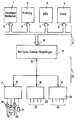
- the drawing shows a transmission unit 11 of a motor vehicle designed as a multiplex transceiver and three sub-distribution devices 17, 23 and 25, the sub-distribution devices 17, 23 and 25 being connected to the transmission unit 11 via a multiplex line system 13.
- the transmission unit 11 has multiplex inputs and outputs 12 to which the multiplex line system 13 is connected.
- the sub-distribution devices 17, 23 and 25 have multiplex inputs and outputs 14, 15 and 16.
- the sub-distribution devices 17, 23 and 25 Four components of the motor vehicle are connected to the sub-distribution devices 17, 23 and 25.
- four further components of the motor vehicle are each connected to the inputs and outputs 22 and 24 of the sub-distribution devices 23 and 25.
- the multiplex line system 13 is operated, for example, in time-division multiplex or frequency division multiplex operation. Output signals of the components connected to the sub-distribution devices 17, 23 and 25 and control signals for the components mentioned are exchanged between the transmitter unit 11 on the one hand and the sub-distribution devices 17, 23 and 25 via the multiplex line system 13. It is possible, for example, that the components 18, 19, 20, 21, 22 and 24 are continuously queried by the transmitting unit 11. But it is also possible that the components mentioned from the transmitter unit 11 can only be queried at previously determined or predeterminable times. It is also possible to use a priority circuit device in order to be able to query or control certain components more frequently or preferably.
- the component output signals queried by the transmission unit 11 or the data words of a binary data system corresponding to these signals can be tapped at data inputs and outputs 10 of the transmission unit 11. Via these data inputs and outputs 10, the transmitting unit 11 also receives data words or signals which are used to control or query the components or the sub-distribution devices 17, 23 and 25.
- a number of special, separately arranged modules are provided for evaluating the data words and signals that can be called up by the transmitter unit 11 at the data outputs 10, which modules in turn have data inputs and outputs.
- a data bus system 9 is arranged between the data inputs and outputs 10 of the transmitter unit 11 and the data inputs and outputs 5, 6, 7 and 8 of the modules 1, 2, 3 and 4. Allows data and signals to be exchanged between the modules 1, 2, 3 and 4 on the one hand and the transmitter unit 11 on the other hand in the usual manner and in the manner of a computer data bus. This exchange of data and signals on the data bus system 9 can e.g. in multiplex mode with addresses and acknowledgment signals.
- module 1 is intended to carry out the usual displays of a motor vehicle, such as, for example, speed, engine speed, operating resource consumption, cooling water temperature, etc.
- Module 1 calculates the required values to be displayed from the output signals of components such as the tachometer, temperature sensor etc. and outputs them to a display field (not shown).
- Module 2 is intended to check all components of the motor vehicle for functional reliability and operating states and, if appropriate, to generate corresponding error signals which can be displayed via module 1.
- Module 3 essentially contains the control unit of an anti-lock braking system. Control signals such as speed, deceleration and slip signals are generated in the usual way in module 3 from the output signals from sensor components.
- module 3 certain control signals are generated in module 3 for the actuators (solenoid valves) of the brake system of the motor vehicle, which is operated with compressed air, for example, which are also connected as components to a sub-distribution device.
- module 4 contains, for the "climate control" function, the computing and switching device for controlling or regulating, for example, the temperature and the fresh air supply to the passenger compartment of the motor vehicle. Work as components to be queried, for example Temperature sensor together with module 4, while the control signals generated in module 4 are supplied to components such as fan motors and heating units.
- Modules 1 and 2 can also work together in such a way that in-vehicle diagnostic procedures for checking the components etc. are carried out and that the corresponding results, e.g. Information about the location and type of errors is displayed by module 1 or saved for later query.
- the module 3 generates addressed query data words which are transferred to the data bus system 9 via the data outputs 7 of the module 3.
- the query data words mentioned are fed to the data inputs 10 of the transmission unit 11 via the data bus system 9.
- the transmission unit 11 assigns these query data words of the module 3 the relevant components, i.e. the wheel sensors to be queried here.
- the transmission unit 11 receives, for example, periodically all the necessary sensor output signals which are generated by the corresponding components, e.g. to the sensor 21 via the assigned sub-distribution device (e.g. 17) and the assigned multiplex connection 14 of the sub-distribution device 17 to the multiplex line system 13.
- the required sensor signals are supplied to the module 3 via the transmitting unit 11 in the form of data words. It is also possible for the transmission unit 11 to contain memories for storing the successive output signals of the components. In this case, the transmitting unit and the sub-distribution devices constantly exchange data and signals, regardless of whether there is a request from a module or not.
- module 3 the sensor signals mentioned are evaluated and, if the motor vehicle tends to lock, are used to generate control signals for the solenoid valves switched on in the brake system of the motor vehicle.
- the control signals mentioned arrive as data words via the data bus system 9 to the transmission unit 11 and finally via the multiplex line system 13 and the sub-distribution devices to the corresponding solenoid valve components.
- the transmission unit 11 may be limited to the mere forwarding and transmission of the mentioned data words or control signals and output signals if the power output stages for the components to be controlled are accommodated in the assigned sub-distribution devices or in the components themselves.
- sub-distribution devices When designing the sub-distribution devices, it is advantageous if all sub-distribution devices are constructed identically. However, it is also possible to use two different types of sub-distribution devices, one of which is used only for connecting components designed as sensors (wheel sensors, temperature sensors, etc.) and the other type for connecting as actuators, display units and also Sensors of trained components.
- the multiplex line system 13 can in any way e.g. be star-shaped or as a ring line system. Accordingly, the data bus system 9 is adapted to the requirements that are specified with regard to the type, quantity, priority and length of the data words.
- the line system of the multiplex line system can be constructed not only from electrical lines but also from signal and control lines of another type (optical, pneumatic, etc.).
Abstract
Description
Die Erfindung betrifft ein Multiplex-System zum Abfragen und Steuern von mehreren Komponenten eines Fahrzeuges gemäß dem Oberbegriff des Patentanspruchs 1.The invention relates to a multiplex system for querying and controlling a plurality of components of a vehicle according to the preamble of patent claim 1.
Aus der EP-A-00 82 300 ist ein solchen Multiplex-System bekannt, dessen Sender mit Mikrocomputern ausgerüstet ist. Diese dienen aber lediglich zur Erzeugung und zum Lesen von Multiplex-Datenwörtern bzw. Befehls-Telegrammen und führen keine intelligenten Steuer- und Regel-Funktionen aus. Zur Erhöhung der Betriebssicherheit sind in der genannten Entgegenhaltung zwei Mikrocomputer parallel geschaltet. Die ebenfalls aus der genannten Entgegenhaltung bekannte Anzeige- und Tastatureinheit enthält ebenfalls keine eigene Intelligenz und ist auch nicht mit einem eigenem Mikrocomputer ausgerüstet.Such a multiplex system is known from EP-A-00 82 300, the transmitter of which is equipped with microcomputers. However, these are only used to generate and read multiplex data words or command telegrams and do not perform any intelligent control functions. To increase operational safety, two microcomputers are connected in parallel in the cited document. The display and keyboard unit, which is also known from the cited document, likewise does not contain its own intelligence and is also not equipped with its own microcomputer.
Durch die DE-A-24 33 025 ist eine Einrichtung zum Steuern und Kontrollieren von elektrischen Schaltvorgängen in einem Kraftfahrzeug bekannt, bei der in der zentralen Sendeeinheit gewisse logische Verknüpfungen von Komponenten-Ausgangssignalen vorgenommen werden, die als Rückmeldesignale über den Zustand von Schaltern und Lampen des Kraftfahrzeuges zur zentralen Sendeeinheit übertragen werden. Eine weitergehende Verarbeitung von Komponenten-Signalen ist bei der bekannten Einrichtung nicht vorgesehen.From DE-A-24 33 025 a device for controlling and monitoring electrical switching operations in a motor vehicle is known, in which certain logical combinations of component output signals are made in the central transmission unit, which act as feedback signals about the state of switches and lamps of the motor vehicle are transmitted to the central transmission unit. No further processing of component signals is provided in the known device.
Es gibt jedoch eine Reihe von Funktionen, die in zunehmendem Maße ebenfalls über ein Multiplex-Leitungssystem ausgeführt werden können. So kann man z.B. daran denken, die für ein Antiblockiersystem abzufragenden Sensoren und anzusteuernden Magnetventile als Komponenten an die Unterverteilungs-Einrichtung eines Multiplex-Leitungssystems anzuschließen. In Anwendung der Lehre der erwähnten DE-A-24 33 025 könnte man weiter daran denken, die zentrale Sendeeinheit so auszubilden, daß diese die für die Funktion "Antiblockiersystem" erforderlichen Abfragen, Auswertungen und Verknüpfungen unter Verwendung von bereits für den Betrieb des Multiplex-Leitungssystems vorhandenen Schaltkreisen mit übernimmt.However, there are a number of functions that can increasingly be performed via a multiplex line system. So you can e.g. remember to connect the sensors and solenoid valves to be checked for an anti-lock braking system as components to the sub-distribution device of a multiplex line system. In application of the teaching of the aforementioned DE-A-24 33 025, one could also think of designing the central transmission unit in such a way that it performs the queries, evaluations and links required for the "anti-lock braking system" function using already for the operation of the multiplex Existing system with takes over.
Insbesondere in dem Fall, daß man noch weitere spezielle Funktionen, wie z.B. "Klimasteuerung", "Türsteuerung" (z.B. in Omnibussen) oder "Anzeigen und Bedienen" realisieren will, würde die zentrale Sendeeinheit sehr aufwendig und damit störanfällig. Ein Ausfall eines Teiles einer solchen zentralen Sendeeinheit könnte die Arbeitsweise aller realisierten weiteren Funktionen gefährden. Im Falle eines Defektes muß u.U. die ganze Sendeeinheit ausgewechselt werden.Especially in the event that other special functions such as e.g. "Central control", "door control" (e.g. in omnibuses) or "display and operation", the central transmission unit would be very complex and therefore prone to failure. A failure of a part of such a central transmission unit could endanger the functioning of all other functions implemented. In the event of a defect, the whole transmitter unit can be replaced.
Der Erfindung liegt deshalb die Aufgabe zugrunde, eine Einrichtung der eingangs genannten Art zu schaffen, die mit geringem Aufwand einen weitgehend sicheren Betrieb ermöglicht.The object of the invention is therefore to create a device of the type mentioned at the outset which enables largely safe operation with little effort.
Diese Aufgabe wird durch die im Patentanspruch 1 angegebene Erfindung gelöst. Weiterbildungen und vorteilhafte Ausführungsbeispiele der Erfindung sind in den Unteransprüchen angegeben.This object is achieved by the invention specified in claim 1. Further developments and advantageous exemplary embodiments the invention are specified in the subclaims.
Die Erfindung weist den Vorteil auf, daß mit geringem Aufwand eine Erweiterung oder Reduzierung der Einrichtung durch einfaches Hinzufügen oder Abtrennen von Modulen verschiedener Funktion möglich ist. Es ist von erheblichem Vorteil, daß die Unterverteilungs-Einrichtungen sowie die zentrale Sendeeinheit unabhängig von dem speziellen Aufbau der anschließbaren Module standardisiert ausgeführt werden können. Es ist lediglich ein Standard über die Anschlüsse der zentralen Sendeeinheit und der Unterverteilung-Einrichtungen und über die Übertragungsweise des Multiplex-Leitungssystems und des Datenbus-Systems erforderlich. Bei einer Störung in einer der Baugruppen muß nur das betreffende Modul oder die vergleichsweise einfach aufgebaute zentrale Sendeeinheit ausgewechselt werden. Darüber hinaus ist es möglich, daß die Module mit Programmen für entsprechende programmierbare Rechner versehen werden können und daß bei einer Weiterentwicklung oder Veränderung der Funktionen des betreffenden Moduls lediglich das Programm ausgewechselt werden muß.The invention has the advantage that the device can be expanded or reduced by simply adding or separating modules of different functions with little effort. It is of considerable advantage that the sub-distribution devices and the central transmission unit can be implemented in a standardized manner regardless of the special structure of the connectable modules. All that is required is a standard for the connections of the central transmission unit and the sub-distribution devices and for the way in which the multiplex line system and the data bus system are transmitted. In the event of a malfunction in one of the modules, only the module in question or the comparatively simple central transmission unit must be replaced. In addition, it is possible that the modules can be provided with programs for corresponding programmable computers and that when the functions of the module in question are further developed or changed, only the program has to be replaced.
Die Erfindung wird anhand eines Ausführungsbeispiels, das in der Zeichnung dargestellt ist, näher erläutert.The invention is explained in more detail using an exemplary embodiment which is illustrated in the drawing.
Die Zeichnung zeigt eine als Multiplex-Sender/Empfänger ausgebildete Sendeeinheit 11 eines Kraftfahrzeugs und drei Unterverteilungs-Einrichtungen 17, 23 und 25, wobei die Unterverteilungs-Einrichtungen 17, 23 und 25, über ein Multiplex-Leitungssystem 13 mit der Sendeeinheit 11 verbunden sind. Die Sendeeinheit 11 weist Multiplex-Eingänge und -Ausgänge 12 auf, an die das Multiplex-Leitungssystem 13 angeschlossen ist. Entsprechend weisen die Unterverteilungs-Einrichtungen 17, 23 und 25 Multiplex-Eingänge und -Ausgänge 14, 15 und 16 auf.The drawing shows a
An die Unterverteilungs-Einrichtungen 17, 23 und 25 sind jeweils vier Komponenten des Kraftfahrzeugs angeschlossen. Dies sind beispielsweise bei der Unterverteilungs-Einrichtung 17 eine Lampe 18, ein Magnetventil 19, ein Elektromotor 20 und ein Sensor 21. Entsprechend sind an die Eingänge und Ausgänge 22 und 24 der Unterverteilungs-Einrichtungen 23 und 25 je vier weitere Komponenten des Kraftfahrzeugs angeschlossen.Four components of the motor vehicle are connected to the
Das Multiplex-Leitungssystem 13 wird beispielsweise im Zeitmultiplex- oder im Frequenzmultiplex-Betrieb betrieben. Über das Multiplex-Leitungssystem 13 werden zwischen der Sendeeinheit 11 einerseits und den Unterverteilungs-Einrichtungen 17, 23 und 25 andererseits Ausgangssignale der an die Unterverteilungs-Einrichtungen 17, 23 und 25 angeschlossenen Komponenten sowie Steuersignale für die erwähnten Komponenten ausgetauscht. Es ist z.B. möglich, daß die Komponenten 18, 19, 20, 21, 22 und 24 ständig von der Sendeeinheit 11 abgefragt werden. Es ist aber auch möglich, daß die erwähnten Komponenten von der Sendeeinheit 11 nur zu zuvor bestimmten oder vorbestimmbaren Zeiten abgefragt werden. Dabei ist noch die Verwendung einer Prioritäts-Schaltungseinrichtung möglich, um bestimmte Komponenten häufiger oder bevorzugt abfragen bzw. ansteuern zu können.The
Die von der Sendeeinheit 11 abgefragten Komponenten-Ausgangssignale bzw. die diesen Signalen entsprechenden Datenwörter eines binären Datensystems, sind an Dateneingängen und -ausgängen 10 der Sendeeinheit 11 abgreifbar. Über diese Dateneingänge und -ausgänge 10 erhält die Sendeeinheit 11 ferner Datenwörter oder Signale zugeführt, die zum Steuern bzw. Abfragen der Komponenten bzw. der Unterverteilungs-Einrichtungen 17, 23 und 25 dienen.The component output signals queried by the
Zum Auswerten der von der Sendeeinheit 11 an den Datenausgängen 10 abrufbaren Datenwörter und Signale ist eine Reihe von speziellen, gesondert angeordneten Modulen vorgesehen, die ihrerseits Dateneingänge und -ausgänge aufweisen. Zwischen den Dateneingängen und -ausgängen 10 der Sendeeinheit 11 und den Dateneingängen und -ausgängen 5, 6, 7 und 8 der Module 1, 2, 3 und 4 ist ein Datenbus-System 9 angeordnet, das z.B. in üblicher Weise und nach Art eines Computer-Datenbusses Daten und Signale zwischen den Modulen 1, 2, 3 und 4 einerseits und der Sendeeinheit 11 andererseits auszutauschen erlaubt. Dieser Austausch von Daten und Signalen auf dem Datenbus-System 9 kann z.B. im Multiplex-Betrieb mit Adressen und Quittiersignalen erfolgen.A number of special, separately arranged modules are provided for evaluating the data words and signals that can be called up by the
Die gesondert angeordneten Module 1, 2, 3 und 4 erfüllen je eine spezielle Funktion. So ist das Modul 1 dafür vorgesehen, die üblichen Anzeigen eines Kraftfahrzeuges wie z.B. Geschwindigkeit, Motordrehzahl, Betriebsmittel-Verbrauch, Kühlwasser-Temperatur etc. vorzunehmen. Aus den Ausgangssignalen von Komponenten wie Drehzahlmesser, Temperaturfühler etc. berechnet das Modul 1 die erforderlichen anzuzeigenden Werte und gibt diese an ein nicht dargestelltes Anzeigefeld. Das Modul 2 ist dafür vorgesehen, alle Komponenten des Kraftfahrzeugs auf Funktionssicherheit und Betriebszustände hin zu überprüfen und gegebenenfalls entsprechende Fehlersignale zu erzeugen, die über das Modul 1 zur Anzeige gebracht werden können. Das Modul 3 enthält im wesentlichen die Regeleinheit eines Antiblockiersystems. Aus den Ausgangs-Signalen von Sensor-Komponenten werden im Modul 3 in üblicher Weise Regelsignale wie z.B. Geschwindigkeits-, Verzögerungs-, und Schlupfsignale erzeugt. Ferner werden im Modul 3 bestimmte Steuersignale für die ebenfalls als Komponenten an eine Unterverteilungs-Einrichtung angeschlossenen Stellglieder (Magnetventile) der z.B. mit Druckluft betriebenen Bremsanlage des Kraftfahrzeugs erzeugt. Das Modul 4 schließlich enthält für die Funktion "Klimasteuerung" die Rechen- und Schaltungseinrichtung zur Steuerung bzw. Regelung z.B. der Temperatur und der Frischluftzuführung des Passagierraumes des Kraftfahrzeugs. Als abzufragende Komponenten arbeiten z.B. Temperatur-Fühler mit dem Modul 4 zusammen, während die im Modul 4 erzeugten Steuersignale Komponenten wie z.B. Lüftermotoren und Wärmeaggregaten zugeführt werden.The separately arranged
Die Module 1 und 2 können auch in der Weise zusammenwirken, daß fahrzeuginterne Diagnoseabläufe zur Prüfung der Komponenten etc. vorgenommen werden und daß die entsprechenden Ergebnisse wie z.B. Informationen über Ort und Art von Fehlern vom Modul 1 angezeigt oder zur späteren Abfrage gespeichert werden.
Ein möglicher Ablauf für eine in einem Modul realisierte Funktion wird anhand des Moduls 3 näher erläutert. Das Modul 3 erzeugt adressierte Abfrage-Datenwörter, die über die Datenausgänge 7 des Moduls 3 auf das Datenbus-System 9 gegeben werden. Über das Datenbus-System 9 werden die erwähnten Abfrage-Datenwörter den Dateneingängen 10 der Sendeeinheit 11 zugeführt. Die Sendeeinheit 11 ordnet diesen Abfrage-Datenwörtern des Moduls 3 die betreffenden Komponenten, d.h. die hier abzufragenden Radsensoren zu. Über den Anschluß 12 erhält die Sendeeinheit 11 beispielsweise periodisch alle erforderlichen Sensor-Ausgangssignale zugeführt, die von den entsprechenden Komponenten wie z.B. dem Sensor 21 über die zugeordnete Unterverteilungs-Einrichtung (z.B. 17) und den zugeordneten Multiplex-Anschluß 14 der Unterverteilungs-Einrichtung 17 auf das Multiplex-Leitungssystem 13 gegeben werden. Auf diese Weise werden also die erforderlichen Sensor-Signale dem Modul 3 über die Sendeeinheit 11 in Form von Datenwörtern zugeführt. Es ist auch möglich, daß die Sendeeinheit 11 Speicher zur Speicherung der aufeinanderfolgenden Ausgangssignale der Komponenten enthält. In diesem Fall tauschen die Sendeeinheit und die Unterverteilungs-Einrichtungen ständig Daten und Signale aus, unabhängig davon, ob eine Anfrage seitens eines Moduls vorliegt oder nicht.A possible sequence for a function implemented in a module is explained in more
In dem Modul 3 werden die erwähnten Sensor-Signale ausgewertet und bei Blockierneigung des Kraftfahrzeugs zur Erzeugung von Steuersignalen für die in die Bremsanlage des Kraftfahrzeugs eingeschalteten Magnetventile verwertet. Die erwähnten Steuersignale gelangen als Datenwörter über das Datenbus-System 9 zu der Sendeeinheit 11 und schließlich über das Multiplex-Leitungssystem 13 und die Unterverteilungs-Einrichtungen zu den entsprechenden Magnetventil-Komponenten.In
Man erkennt, daß die Reihe der Module 2 bis 4 beliebig erweitert oder verringert werden kann, ohne daß in der Sendeeinheit 11 eine Änderung vorgenommen werden muß. Die Sendeeinheit 11 kann sich gegebenenfalls auf die bloße Weiterleitung und Ubertragung der erwähnten Datenwörter bzw. Steuersignale und Ausgangssignale beschränken, wenn die Leistungsendstufen für die anzusteuernden Komponenten in den zugeordneten Unterverteilungs-Einrichtungen oder in den Komponenten selbst untergebracht sind.It can be seen that the row of
Für den Fall, daß ein Modul ein einem programmierbaren Rechner zugeordnetes Programm enthält, ist eine Anpassung des Moduls an geänderte Forderungen bezüglich der betreffenden Funktion durch einfachen Austausch des Programms möglich.In the event that a module contains a program assigned to a programmable computer, it is possible to adapt the module to changed requirements regarding the function concerned by simply exchanging the program.
Bei der Ausbildung der Unterverteilungs-Einrichtungen ist es vorteilhaft, wenn alle Unterverteilungs-Einrichtungen identisch aufgebaut sind. Es ist aber auch möglich, zwei verschiedene Typen von Unterverteilungs-Einrichtungen zu verwenden, von denen der eine Typ nur zum Anschluß von als Sensoren (Radsensoren, Temperaturfühler etc.) ausgebildeten Komponenten dient und der andere Typ zum Anschluß von als Stellglieder, Anzeigeeinheiten und auch Sensoren ausgebildeter Komponenten dient.When designing the sub-distribution devices, it is advantageous if all sub-distribution devices are constructed identically. However, it is also possible to use two different types of sub-distribution devices, one of which is used only for connecting components designed as sensors (wheel sensors, temperature sensors, etc.) and the other type for connecting as actuators, display units and also Sensors of trained components.
Das Multiplex-Leitungssystem 13 kann in beliebiger Weise z.B. sternförmig oder als Ringleitungssystem ausgebildet sein. Entsprechend wird das Datenbus-System 9 an die Anforderungen angepaßt, die hinsichtlich Art, Menge, Priorität und Länge der Datenwörter vorgegeben sind.The
Das Leitungssystem des Multiplex-Leitungssystems kann außer aus elektrischen Leitungen auch aus Signal- und Steuerleitungen anderer Art (optisch, pneumatisch etc.) aufgebaut sein.The line system of the multiplex line system can be constructed not only from electrical lines but also from signal and control lines of another type (optical, pneumatic, etc.).
Claims (7)
- A multiplex system for interrogating and controlling several components (18, 19, 20, 21) of a vehicle, having the following features:a) several sub-distribution arrangements (17, 23, 25) are provided, to each of which several of the components are connected;b) a central transmitter unit (11) is provided, to which the sub-distribution arrangements (17, 23, 25) are connected through a multiplex line system (13);c) a display and servicing unit (1) is connected to the central transmitter unit (11) through a bus (9),
characterised by the following features:d) the central transmitter unit (11) has an additional data connection (10) of defined interface,e) primary modules (2, 3, 4) with their own intelligence and their own microcomputers are arranged to to be connected through a bus system (9) to the additional data connection (10) using plug-in devices which serve to control or regulate different vehicle systems;f) the central transmitter unit (11) relays the commands of the modules (2, 3, 4) to the associated components (18, 19, 20, 21),g) the central transmitter unit (11) interrogates the components (18, 19, 20, 21) in succession or, as required, according to priority, and conveys the signals of components constructed as sensors (21) in succession or as required to the associated modules. - A multiplex line system according to claim 1, characterized in that the data bus system (9) is constructed so that several modules (1, 2, 3, 4) can exchange data with the central transmitter unit (11) in multiplex operation.
- A multiplex line system according to claim 1, characterized in that the sub-distribution arrangements (17, 23, 25) are of identical construction.
- A multiplex line system according to at least one of claims 1 to 3, characterized in that two different types of sub-distribution arrangements are provided, of which one type (23) serves merely for connection of components constructed as sensors, and of which the other type (17, 25) serves for connection of components constructed as actuators, display units and sensors.
- A multiplex line system according to at least one of the preceding claims, characterized in that the central transmitter unit (11) contains at least one memory for storing several successive component output signals.
- A multiplex line system according to at least one of the preceding claims, characterized in that the sub-distribution arrangements (17, 23, 25) and the multiplex line system (13) are constructed so that the components of the sub-distribution arrangements (17, 23, 25) can be interrogated and/or controlled at any time by means of addressed commands.
- A multiplex line system according to at least one of the preceding claims, characterized in that a priority switching arrangement for preferred transmission of predetermined data and signals is provided for the transmission of data and signals on the data bus system (9) and/or on the multiplex line system (13).
Priority Applications (1)
| Application Number | Priority Date | Filing Date | Title |
|---|---|---|---|
| AT84105232T ATE56187T1 (en) | 1983-10-04 | 1984-05-09 | DEVICE FOR REQUESTING AND CONTROLLING SEVERAL COMPONENTS OF A VEHICLE. |
Applications Claiming Priority (2)
| Application Number | Priority Date | Filing Date | Title |
|---|---|---|---|
| DE19833335932 DE3335932A1 (en) | 1983-10-04 | 1983-10-04 | DEVICE FOR INQUIRING AND CONTROLLING SEVERAL COMPONENTS OF A VEHICLE |
| DE3335932 | 1983-10-04 |
Publications (4)
| Publication Number | Publication Date |
|---|---|
| EP0136398A2 EP0136398A2 (en) | 1985-04-10 |
| EP0136398A3 EP0136398A3 (en) | 1987-10-07 |
| EP0136398B1 EP0136398B1 (en) | 1990-09-05 |
| EP0136398B2 true EP0136398B2 (en) | 1997-08-20 |
Family
ID=6210856
Family Applications (1)
| Application Number | Title | Priority Date | Filing Date |
|---|---|---|---|
| EP84105232A Expired - Lifetime EP0136398B2 (en) | 1983-10-04 | 1984-05-09 | Questioning and controlling device for several vehicle components |
Country Status (5)
| Country | Link |
|---|---|
| US (1) | US4584487A (en) |
| EP (1) | EP0136398B2 (en) |
| JP (1) | JPS60135343A (en) |
| AT (1) | ATE56187T1 (en) |
| DE (2) | DE3335932A1 (en) |
Families Citing this family (55)
| Publication number | Priority date | Publication date | Assignee | Title |
|---|---|---|---|---|
| DE3506118A1 (en) * | 1985-02-22 | 1986-08-28 | Robert Bosch Gmbh, 7000 Stuttgart | Method for operating a data processing system for motor vehicles |
| JPS6229247A (en) * | 1985-07-29 | 1987-02-07 | Nippon Soken Inc | On-vehicle local area network |
| US4715031A (en) * | 1985-09-23 | 1987-12-22 | Ford Motor Company | Vehicular data transfer communication system |
| GB2189333B (en) * | 1986-03-20 | 1989-11-15 | Lucas Electrical Electronics A | Vehicle condition monitoring system |
| JPS63133201A (en) * | 1986-11-25 | 1988-06-06 | Mitsubishi Electric Corp | Vehicle controller |
| US4677308A (en) * | 1986-12-22 | 1987-06-30 | Chrysler Motors Corporation | Switch status monitoring system, single wire bus, smart sensor arrangement therefor |
| US4736367A (en) * | 1986-12-22 | 1988-04-05 | Chrysler Motors Corporation | Smart control and sensor devices single wire bus multiplex system |
| IT1198279B (en) * | 1986-12-31 | 1988-12-21 | Alfa Romeo Auto Spa | ELECTRIC CIRCUIT FOR A VEHICLE |
| JPH0667707B2 (en) * | 1987-04-08 | 1994-08-31 | 株式会社日立製作所 | Integrated wiring device for automobiles |
| SE457494B (en) * | 1987-05-07 | 1988-12-27 | Ericsson Telefon Ab L M | DEVICE FOR TIME MULTIPLEX TRANSFER OF INFORMATION BETWEEN VEHICLE COMPONENTS |
| US4804937A (en) * | 1987-05-26 | 1989-02-14 | Motorola, Inc. | Vehicle monitoring arrangement and system |
| DE3730468A1 (en) * | 1987-09-08 | 1989-03-16 | Bergmann Kabelwerke Ag | ON-BOARD NETWORK FOR MOTOR VEHICLES AND METHOD FOR OPERATING THE ON-BOARD NETWORK |
| US4791311A (en) * | 1987-09-28 | 1988-12-13 | Sprague Electric Company | Two-terminal multiplexable sensor |
| US4845708A (en) * | 1987-10-09 | 1989-07-04 | Amp Incorporated | Vehicle multiplex system |
| US4907222A (en) * | 1988-08-17 | 1990-03-06 | Nuvatec, Inc. | Vehicle multiplex system |
| US4930049A (en) * | 1988-12-27 | 1990-05-29 | General Electric Company | Optical multiplexed electrical distribution system particularly suited for vehicles |
| US4956561A (en) * | 1988-12-27 | 1990-09-11 | Caterpillar Inc. | Smart power connector |
| US5079437A (en) * | 1990-03-20 | 1992-01-07 | The United States Of America As Represented By The Secretary Of The Army | Multi-voltage power supply |
| JP2904298B2 (en) * | 1990-03-30 | 1999-06-14 | マツダ株式会社 | Multiplex transmission equipment for vehicles |
| JP3165430B2 (en) * | 1990-08-10 | 2001-05-14 | マツダ株式会社 | Multiplex transmission equipment for vehicles |
| EP0475406B1 (en) * | 1990-09-13 | 1997-04-23 | Mazda Motor Corporation | Multiplex transmission system for vehicles |
| DE4029333A1 (en) * | 1990-09-15 | 1992-03-19 | Teves Gmbh Alfred | Modular control for vehicle - has logic connections between pedal sensors and servo system for controls |
| JP2857501B2 (en) * | 1991-02-18 | 1999-02-17 | マツダ株式会社 | Multiplex transmission equipment |
| EP0507150A3 (en) * | 1991-03-22 | 1992-12-23 | Nisva S.R.L. | Control and power supply plant, particularly for fluid actuators and the like |
| DE4111023C2 (en) * | 1991-04-05 | 2003-11-20 | Bosch Gmbh Robert | Electronic system for a vehicle |
| EP0511794B2 (en) * | 1991-04-26 | 2002-03-13 | Pioneer Electronic Corporation | System for data communication on automobile |
| DE4140803C2 (en) * | 1991-12-11 | 1995-05-18 | Webasto Ag Fahrzeugtechnik | Circuit arrangement for electronic control devices of vehicle additional devices |
| JPH05276561A (en) * | 1992-03-30 | 1993-10-22 | Mazda Motor Corp | Multiplex communication equipment |
| US5262683A (en) * | 1992-04-20 | 1993-11-16 | Ford Motor Company | Method for specifying operating characteristics of integrated circuits |
| DE4235539B4 (en) * | 1992-10-21 | 2006-09-21 | Rockinger Spezialfabrik für Anhängerkupplungen GmbH & Co | Towing, in particular semitrailer |
| DE4420425B4 (en) * | 1994-06-10 | 2006-06-01 | Bayerische Motoren Werke Ag | Electronic composite system in motor vehicles with identically constructed electrical sub-distribution devices |
| US5704038A (en) * | 1994-09-30 | 1997-12-30 | Itt Automotive Electrical Systems, Inc. | Power-on-reset and watchdog circuit and method |
| US5493190A (en) * | 1994-09-30 | 1996-02-20 | Itt Automotive Electrical Systems, Inc. | Windshield wiper auto-delay control interface |
| EP0721064B1 (en) * | 1994-12-02 | 2002-02-20 | Denso Corporation | Vehicular controller |
| JPH08284504A (en) * | 1995-04-11 | 1996-10-29 | Nissan Motor Co Ltd | Key-less entry controller |
| US6242876B1 (en) | 1995-06-07 | 2001-06-05 | Valeo Electrical Systems, Inc. | Intermittent windshield wiper controller |
| US5808371A (en) * | 1995-09-05 | 1998-09-15 | Hitachi, Ltd. | Apparatus for driving electrical loads provided at a vehicle |
| DE19609009A1 (en) * | 1996-03-08 | 1997-09-11 | Edag Eng & Design Ag | Electrical power supply to several loads |
| DE19720285A1 (en) * | 1997-05-15 | 1998-11-19 | Bosch Gmbh Robert | Process for the tamper-proof configuration of a motor vehicle control unit and control unit |
| US6182171B1 (en) * | 1997-06-06 | 2001-01-30 | Nissan Motor Co., Ltd. | Information communication system and method applicable to in-vehicle networking architecture |
| ES2147119B1 (en) * | 1998-03-10 | 2001-03-16 | Mecanismos Aux Es Ind S L | SYSTEM TO TRANSFER BINARY INFORMATION. |
| DE19840484A1 (en) * | 1998-09-04 | 2000-03-09 | Bosch Gmbh Robert | Vehicle computer arrangement |
| US7359775B2 (en) * | 2001-06-13 | 2008-04-15 | Hunter Engineering Company | Method and apparatus for information transfer in vehicle service systems |
| FR2829255B1 (en) * | 2001-08-30 | 2003-12-12 | Valeo Vision | DEVICE FOR CONFIGURING AN ELECTRONIC MODULE AND MULTIPLEX BUS NETWORK WITH MULTIPLE LINES |
| US7049938B2 (en) * | 2001-10-04 | 2006-05-23 | The Yokohama Rubber Company, Ltd. | Intra-vehicle LAN system combining electric power supply |
| US7769346B1 (en) * | 2003-10-31 | 2010-08-03 | Johnson Controls Technology Company | Wireless electrical connectivity system for use in a vehicle |
| DE102007021646A1 (en) | 2007-05-09 | 2008-11-13 | Wabco Gmbh | modulator |
| EP2673178B1 (en) | 2011-02-09 | 2018-10-17 | Allison Transmission, Inc. | Scavenge pump oil level control system and method |
| KR20140003588A (en) | 2011-02-17 | 2014-01-09 | 알리손 트랜스미션, 인크. | Hydraulic system and method for hybrid vehicle |
| KR20140006941A (en) | 2011-03-11 | 2014-01-16 | 알리손 트랜스미션, 인크. | Clogged filter detection system and method |
| AU2012273001B2 (en) | 2011-06-22 | 2015-04-23 | Allison Transmission, Inc. | Low level oil detection system and method |
| EP2756650B1 (en) * | 2011-09-12 | 2020-01-22 | Continental Teves AG & Co. OHG | Device for distributing data about a vehicle |
| US10649948B2 (en) * | 2011-10-05 | 2020-05-12 | Analog Devices, Inc. | Two-wire communication systems and applications |
| US9946679B2 (en) | 2011-10-05 | 2018-04-17 | Analog Devices, Inc. | Distributed audio coordination over a two-wire communication bus |
| DE102012101654B3 (en) | 2012-02-29 | 2013-08-08 | Krauss-Maffei Wegmann Gmbh & Co. Kg | Military vehicle |
Family Cites Families (15)
| Publication number | Priority date | Publication date | Assignee | Title |
|---|---|---|---|---|
| JPS5049586A (en) * | 1973-09-03 | 1975-05-02 | ||
| DE2433025A1 (en) * | 1974-07-10 | 1976-01-22 | Bosch Gmbh Robert | METHOD AND DEVICE FOR CONTROLLING AND MONITORING ELECTRICAL SWITCHING OPERATIONS, IN PARTICULAR IN MOTOR VEHICLES |
| JPS5149618A (en) * | 1974-10-28 | 1976-04-30 | Fujitsu Ltd | SERUFUSHIFUTOGATAGASUHODENPANERUNO KUDOHOHO |
| EP0000427A1 (en) * | 1977-07-09 | 1979-01-24 | LUCAS INDUSTRIES public limited company | Road vehicle electrical systems |
| DE2815303A1 (en) * | 1978-04-08 | 1979-10-18 | Bosch Gmbh Robert | Telecontrol system esp. for vehicles - has ring circuits to outstations for power, synchronisation and control by use of clock pulses |
| JPS5840751Y2 (en) * | 1979-04-23 | 1983-09-13 | マツダ株式会社 | Power supply control device for automotive electrical components |
| US4419666A (en) * | 1979-07-02 | 1983-12-06 | Sangamo Weston, Inc. | System for controlling power distribution to customer loads |
| JPS5780681A (en) * | 1980-11-10 | 1982-05-20 | Hitachi Ltd | Concentrated wiring device for vehicle |
| JPS5790106A (en) * | 1980-11-26 | 1982-06-04 | Nippon Denso Co Ltd | Driving indicator for automobile |
| DE3103884A1 (en) * | 1981-02-05 | 1982-09-02 | Robert Bosch Gmbh, 7000 Stuttgart | REMOTE CONTROL SYSTEM FOR SELECTIVE CONTROL OF CONSUMERS |
| US4463341A (en) * | 1981-06-01 | 1984-07-31 | Aisin Seiki Kabushiki Kaisha | Single conductor multi-frequency electric wiring system for vehicles |
| DE3149142A1 (en) * | 1981-12-11 | 1983-06-23 | Wabco Westinghouse Fahrzeugbremsen GmbH, 3000 Hannover | MULTIPLEX WIRING SYSTEM FOR VEHICLES |
| DE3151628C2 (en) * | 1981-12-28 | 1985-09-19 | SWF Auto-Electric GmbH, 7120 Bietigheim-Bissingen | Switching arrangement for evaluating analog measured values, in particular for motor vehicles |
| DE3207916A1 (en) * | 1982-03-04 | 1983-09-15 | Fiat Auto S.p.A., 10135 Turin | Electronic system for collecting information which is supplied by a multiplicity of sensors installed on a motor vehicle |
| US4538262A (en) * | 1983-08-03 | 1985-08-27 | Rca Corporation | Multiplex bus system for controlling the transmission of data between a master control unit and a plurality of remotely located receiver-transmitter units |
-
1983
- 1983-10-04 DE DE19833335932 patent/DE3335932A1/en not_active Ceased
-
1984
- 1984-05-09 EP EP84105232A patent/EP0136398B2/en not_active Expired - Lifetime
- 1984-05-09 AT AT84105232T patent/ATE56187T1/en not_active IP Right Cessation
- 1984-05-09 DE DE8484105232T patent/DE3483126D1/en not_active Expired - Lifetime
- 1984-10-01 JP JP59204202A patent/JPS60135343A/en active Granted
- 1984-10-02 US US06/657,108 patent/US4584487A/en not_active Expired - Lifetime
Also Published As
| Publication number | Publication date |
|---|---|
| EP0136398A2 (en) | 1985-04-10 |
| ATE56187T1 (en) | 1990-09-15 |
| DE3483126D1 (en) | 1990-10-11 |
| EP0136398A3 (en) | 1987-10-07 |
| DE3335932A1 (en) | 1985-04-18 |
| EP0136398B1 (en) | 1990-09-05 |
| JPS60135343A (en) | 1985-07-18 |
| US4584487A (en) | 1986-04-22 |
| JPH0347217B2 (en) | 1991-07-18 |
Similar Documents
| Publication | Publication Date | Title |
|---|---|---|
| EP0136398B2 (en) | Questioning and controlling device for several vehicle components | |
| DE69923593T2 (en) | CONFIGURATION PROGRAMMING OF INPUT / OUTPUT NETWORK CONNECTION UNITS IN A MULTIPLEXED MOTOR VEHICLE COMMUNICATION SYSTEM | |
| EP0307344B1 (en) | Wiring for motor vehicles, and process for operating it | |
| DE102012102173B4 (en) | Reconfigurable interface-based electrical architecture | |
| DE102010053803B3 (en) | Method for operating a vehicle electrical system of a motor vehicle and then working bus system | |
| EP3584140B1 (en) | Vehicle and method and apparatus for controlling a safety-relevant process | |
| DE4126449C2 (en) | Control device for vehicles | |
| WO2013110394A1 (en) | Method for operating at least two data processing units with high availability, in particular in a vehicle, and device for operating a machine | |
| EP1719688A1 (en) | Data communication system for railway vehicles | |
| DE10219832B4 (en) | Method for coding control devices in means of transport | |
| WO2016206901A1 (en) | Control arrangement for a vehicle | |
| DE19911824C2 (en) | Control cabinet monitoring system | |
| DE102008039767A1 (en) | Control system for an electronic device in a vehicle | |
| EP0941894B1 (en) | Circuit arrangement for communication and diagnostic of a plurality of electrical components | |
| EP2075655B1 (en) | Safety control | |
| EP3049289B1 (en) | Integrated and combined door-operating system for commercial vehicles | |
| EP0631921B1 (en) | Apparatus for controlling and regulating electric, electronic or electro-mechanic components in railway vehicles | |
| DE102019132428A1 (en) | Function-oriented electronics architecture | |
| DE69737556T2 (en) | ARRANGEMENT FOR AGGREGATE ON A NUMBER OF SENSOR SIGNALS AND FOR CONTROLLING A NUMBER OF MOTOR OPERATING DEVICES, AND CONTROL DEVICE | |
| DE102010035300B4 (en) | Apparatus and method for operating multiple components on simple electrical data links | |
| DE102009019957A1 (en) | Vehicle has computer unit, where computer unit is central computer unit, in which two controllers are integrated, and computer unit is arranged in interior of vehicle and controls or regulates multiple vehicle functions | |
| DE102011105617A1 (en) | Motor vehicle with a variety of operating components | |
| WO2017144176A1 (en) | Aircraft | |
| DE102016117169A1 (en) | System for energy and / or data transmission | |
| DE60314928T2 (en) | Circuit arrangement for an electronic control module for implementing communication protocols |
Legal Events
| Date | Code | Title | Description |
|---|---|---|---|
| PUAI | Public reference made under article 153(3) epc to a published international application that has entered the european phase |
Free format text: ORIGINAL CODE: 0009012 |
|
| AK | Designated contracting states |
Designated state(s): AT DE FR GB IT SE |
|
| RTI1 | Title (correction) | ||
| PUAL | Search report despatched |
Free format text: ORIGINAL CODE: 0009013 |
|
| AK | Designated contracting states |
Kind code of ref document: A3 Designated state(s): AT DE FR GB IT SE |
|
| 17P | Request for examination filed |
Effective date: 19870907 |
|
| 17Q | First examination report despatched |
Effective date: 19880902 |
|
| GRAA | (expected) grant |
Free format text: ORIGINAL CODE: 0009210 |
|
| AK | Designated contracting states |
Kind code of ref document: B1 Designated state(s): AT DE FR GB IT SE |
|
| REF | Corresponds to: |
Ref document number: 56187 Country of ref document: AT Date of ref document: 19900915 Kind code of ref document: T |
|
| ITF | It: translation for a ep patent filed |
Owner name: JACOBACCI & PERANI S.P.A. |
|
| REF | Corresponds to: |
Ref document number: 3483126 Country of ref document: DE Date of ref document: 19901011 |
|
| ET | Fr: translation filed | ||
| GBT | Gb: translation of ep patent filed (gb section 77(6)(a)/1977) | ||
| PLBI | Opposition filed |
Free format text: ORIGINAL CODE: 0009260 |
|
| 26 | Opposition filed |
Opponent name: BAYERISCHE MOTOREN WERKE AG, PATENTABTEILUNG AJ-3, Effective date: 19910605 |
|
| RAP2 | Party data changed (patent owner data changed or rights of a patent transferred) |
Owner name: WABCO VERMOEGENSVERWALTUNGS-GMBH |
|
| ITTA | It: last paid annual fee | ||
| EAL | Se: european patent in force in sweden |
Ref document number: 84105232.7 |
|
| RAP2 | Party data changed (patent owner data changed or rights of a patent transferred) |
Owner name: WABCO GMBH |
|
| PLAW | Interlocutory decision in opposition |
Free format text: ORIGINAL CODE: EPIDOS IDOP |
|
| PLAW | Interlocutory decision in opposition |
Free format text: ORIGINAL CODE: EPIDOS IDOP |
|
| PUAH | Patent maintained in amended form |
Free format text: ORIGINAL CODE: 0009272 |
|
| STAA | Information on the status of an ep patent application or granted ep patent |
Free format text: STATUS: PATENT MAINTAINED AS AMENDED |
|
| 27A | Patent maintained in amended form |
Effective date: 19970820 |
|
| AK | Designated contracting states |
Kind code of ref document: B2 Designated state(s): AT DE FR GB IT SE |
|
| ITF | It: translation for a ep patent filed |
Owner name: JACOBACCI & PERANI S.P.A. |
|
| ET3 | Fr: translation filed ** decision concerning opposition | ||
| GBTA | Gb: translation of amended ep patent filed (gb section 77(6)(b)/1977) | ||
| REG | Reference to a national code |
Ref country code: GB Ref legal event code: IF02 |
|
| PGFP | Annual fee paid to national office [announced via postgrant information from national office to epo] |
Ref country code: AT Payment date: 20020307 Year of fee payment: 19 |
|
| PGFP | Annual fee paid to national office [announced via postgrant information from national office to epo] |
Ref country code: GB Payment date: 20020508 Year of fee payment: 19 |
|
| PGFP | Annual fee paid to national office [announced via postgrant information from national office to epo] |
Ref country code: SE Payment date: 20020523 Year of fee payment: 19 |
|
| PGFP | Annual fee paid to national office [announced via postgrant information from national office to epo] |
Ref country code: FR Payment date: 20020529 Year of fee payment: 19 |
|
| PGFP | Annual fee paid to national office [announced via postgrant information from national office to epo] |
Ref country code: DE Payment date: 20030503 Year of fee payment: 20 |
|
| PG25 | Lapsed in a contracting state [announced via postgrant information from national office to epo] |
Ref country code: GB Free format text: LAPSE BECAUSE OF NON-PAYMENT OF DUE FEES Effective date: 20030509 Ref country code: AT Free format text: LAPSE BECAUSE OF NON-PAYMENT OF DUE FEES Effective date: 20030509 |
|
| PG25 | Lapsed in a contracting state [announced via postgrant information from national office to epo] |
Ref country code: SE Free format text: LAPSE BECAUSE OF NON-PAYMENT OF DUE FEES Effective date: 20030510 |
|
| GBPC | Gb: european patent ceased through non-payment of renewal fee |
Effective date: 20030509 |
|
| EUG | Se: european patent has lapsed | ||
| PG25 | Lapsed in a contracting state [announced via postgrant information from national office to epo] |
Ref country code: FR Free format text: LAPSE BECAUSE OF NON-PAYMENT OF DUE FEES Effective date: 20040130 |
|
| REG | Reference to a national code |
Ref country code: FR Ref legal event code: ST |
|
| APAH | Appeal reference modified |
Free format text: ORIGINAL CODE: EPIDOSCREFNO |