EP0136202A1 - Filter provided with a cleaning device - Google Patents
Filter provided with a cleaning device Download PDFInfo
- Publication number
- EP0136202A1 EP0136202A1 EP84401581A EP84401581A EP0136202A1 EP 0136202 A1 EP0136202 A1 EP 0136202A1 EP 84401581 A EP84401581 A EP 84401581A EP 84401581 A EP84401581 A EP 84401581A EP 0136202 A1 EP0136202 A1 EP 0136202A1
- Authority
- EP
- European Patent Office
- Prior art keywords
- orifices
- sectors
- distributor
- communication
- filter
- Prior art date
- Legal status (The legal status is an assumption and is not a legal conclusion. Google has not performed a legal analysis and makes no representation as to the accuracy of the status listed.)
- Granted
Links
- 238000004140 cleaning Methods 0.000 title description 2
- 238000002955 isolation Methods 0.000 abstract 1
- 238000004519 manufacturing process Methods 0.000 abstract 1
- 238000001914 filtration Methods 0.000 description 27
- 239000012530 fluid Substances 0.000 description 26
- 208000031968 Cadaver Diseases 0.000 description 5
- 239000012535 impurity Substances 0.000 description 4
- 238000005406 washing Methods 0.000 description 3
- 230000002093 peripheral effect Effects 0.000 description 2
- 239000000446 fuel Substances 0.000 description 1
- 239000010705 motor oil Substances 0.000 description 1
- 238000007789 sealing Methods 0.000 description 1
Images


Classifications
-
- B—PERFORMING OPERATIONS; TRANSPORTING
- B01—PHYSICAL OR CHEMICAL PROCESSES OR APPARATUS IN GENERAL
- B01D—SEPARATION
- B01D29/00—Filters with filtering elements stationary during filtration, e.g. pressure or suction filters, not covered by groups B01D24/00 - B01D27/00; Filtering elements therefor
- B01D29/39—Filters with filtering elements stationary during filtration, e.g. pressure or suction filters, not covered by groups B01D24/00 - B01D27/00; Filtering elements therefor with hollow discs side by side on, or around, one or more tubes, e.g. of the leaf type
- B01D29/41—Filters with filtering elements stationary during filtration, e.g. pressure or suction filters, not covered by groups B01D24/00 - B01D27/00; Filtering elements therefor with hollow discs side by side on, or around, one or more tubes, e.g. of the leaf type mounted transversely on the tube
- B01D29/413—Filters with filtering elements stationary during filtration, e.g. pressure or suction filters, not covered by groups B01D24/00 - B01D27/00; Filtering elements therefor with hollow discs side by side on, or around, one or more tubes, e.g. of the leaf type mounted transversely on the tube divided in sectors
-
- B—PERFORMING OPERATIONS; TRANSPORTING
- B01—PHYSICAL OR CHEMICAL PROCESSES OR APPARATUS IN GENERAL
- B01D—SEPARATION
- B01D29/00—Filters with filtering elements stationary during filtration, e.g. pressure or suction filters, not covered by groups B01D24/00 - B01D27/00; Filtering elements therefor
- B01D29/50—Filters with filtering elements stationary during filtration, e.g. pressure or suction filters, not covered by groups B01D24/00 - B01D27/00; Filtering elements therefor with multiple filtering elements, characterised by their mutual disposition
- B01D29/52—Filters with filtering elements stationary during filtration, e.g. pressure or suction filters, not covered by groups B01D24/00 - B01D27/00; Filtering elements therefor with multiple filtering elements, characterised by their mutual disposition in parallel connection
- B01D29/54—Filters with filtering elements stationary during filtration, e.g. pressure or suction filters, not covered by groups B01D24/00 - B01D27/00; Filtering elements therefor with multiple filtering elements, characterised by their mutual disposition in parallel connection arranged concentrically or coaxially
-
- B—PERFORMING OPERATIONS; TRANSPORTING
- B01—PHYSICAL OR CHEMICAL PROCESSES OR APPARATUS IN GENERAL
- B01D—SEPARATION
- B01D29/00—Filters with filtering elements stationary during filtration, e.g. pressure or suction filters, not covered by groups B01D24/00 - B01D27/00; Filtering elements therefor
- B01D29/62—Regenerating the filter material in the filter
- B01D29/66—Regenerating the filter material in the filter by flushing, e.g. counter-current air-bumps
- B01D29/68—Regenerating the filter material in the filter by flushing, e.g. counter-current air-bumps with backwash arms, shoes or nozzles
- B01D29/682—Regenerating the filter material in the filter by flushing, e.g. counter-current air-bumps with backwash arms, shoes or nozzles with a rotary movement with respect to the filtering element
-
- F—MECHANICAL ENGINEERING; LIGHTING; HEATING; WEAPONS; BLASTING
- F01—MACHINES OR ENGINES IN GENERAL; ENGINE PLANTS IN GENERAL; STEAM ENGINES
- F01M—LUBRICATING OF MACHINES OR ENGINES IN GENERAL; LUBRICATING INTERNAL COMBUSTION ENGINES; CRANKCASE VENTILATING
- F01M1/00—Pressure lubrication
- F01M1/10—Lubricating systems characterised by the provision therein of lubricant venting or purifying means, e.g. of filters
- F01M2001/1007—Lubricating systems characterised by the provision therein of lubricant venting or purifying means, e.g. of filters characterised by the purification means combined with other functions
- F01M2001/1021—Lubricating systems characterised by the provision therein of lubricant venting or purifying means, e.g. of filters characterised by the purification means combined with other functions comprising self cleaning systems
Definitions
- Filters are already known, in particular for engine oil or fuel, provided with unclogging devices.
- Such a filter is constituted by a stack of several distinct filter elements assembled together so as to form an annular sheath comprising at least one cylindrical face, and, constituted, each filter element, by several sectors isolated from each other , however, on the one hand, each filter element is provided on its external and internal radial peripheries with communication orifices of each of its sectors with said peripheries, on the other hand, a sectioning distributor is rotatably mounted coaxially with the axis of said at least one cylindrical face and comprises a sectioning chamber capable of isolating a first sector of any filter element from the other sectors of said element, by communicating only, at this determined moment, with said first sector at by means of a passage formed in the distributor and of the communication orifice of said first sector.
- the unclogging device is constituted by the combination of the arrangement of the communication orifices of the filter elements with the passage of the distributor, which allows the filtration screens of the first sectors to be crossed, against the current, by the clean fluid already filtered by the other sectors, and thus to be rid of the impurities which had previously deposited there.
- the distributor driven in rotation therefore isolates at each rotation, at least one sector of each filter element, and sometimes more.
- a sector thus isolated is a sector which functions to decolmate, and which, consequently, does not take part in the main filtration of the product to be purified.
- the invention in a filter as previously described, and while retaining a similar unclogging principle, intends to adapt it to reduce the number of working sectors, to at a given time, in unclogging, and for, consequently, correspondingly increasing the number of sectors participating in the main filtration, and, by this means, increasing the overall efficiency of the filter.
- the shape of said passage and the arrangement of the communication orifices which may be located opposite are such that the first sectors of only part of all the filter elements are, in a relative position determined by the distributor with respect to the stack of filter elements, in communication with said sectioning chamber.
- the main advantage of the filters according to the invention is to neutralize for the unclogging phase, a number of sectors of filter elements substantially lower than what was necessary before.
- it is possible to produce, in a given space, a filter having a better efficiency than before, or even capable of treating a volume of fluid to be filtered greater than the volume treated by the previous filters.
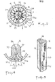
- the ring 15 a view of which can be seen developed in FIG. 3, superimposed on a view of the face of the distributor 16 arranged opposite, has through holes 35, which in the embodiment of FIGS. 1 to 5 are aligned on generatrices 36 of the ring 15 and correspond to the orifices of the internal periphery of the main stack 4.
- This stack 4 also has orifices formed on its external periphery, these orifices of the internal and external peripheries being separated by the sieves of the elements filters.
- the structure of the secondary stack 7 is similar, with orifices on the internal and external peripheries separated by the filtration screens.
- the fluid to be filtered admitted into the inlet chamber 21, reaches the groove 20 of the distributor, passes through the orifices of the internal periphery of the sectors 24 of the filter elements 5 which are opposite the groove 20, then through the corresponding holes 35 of the ring 15, pass through the screens, then the orifices of the external periphery of the same sectors, and filtered spring in the main chamber 11, to then be evacuated through the evacuation connector 3.
- part of the filtered fluid contained in the main chamber 11 passes, in the opposite direction to the previous one, from the external periphery towards the internal periphery of the stack 4, those of the sectors 23 of the filtration elements 5 which are arranged opposite the 'one of the grooves 22a, 22b, 22c (in fact, the groove 22a in the configuration of Figure 3).
- This small portion of filtered fluid makes it possible to free from the sieves of said sectors 23 the impurities which had previously deposited therein and thus, by cleaning these sieves, to make them again suitable for effective filtration.
- This part of the fluid, which passes through the sieves of the sectors 23 is collected by the groove arranged opposite these sectors (22a of FIG. 3) and directed, through the conduit 25 towards the secondary chamber 12.
- the fluid charged with impurities, contained in the secondary chamber 12 passes through, from the external periphery towards the internal periphery of the sectors of the filtration elements of the stack, which are opposite the groove 29 of the distributor 16, and, filtered by the sieves of said sectors, from the groove 29 is directed by the conduit 30, the chamber 31 and the conduit 34, towards the discharge connector 6 for new use.
- part of this filtered fluid contained in the upper chamber 31 is used as the supply fluid for the motor 17 (conduits 32).
- the novelty lies in the fact that during the "unclogging" operation of the sieves of the filtration elements 5 of the main stack 4, the sectors 23 of a single column are washed of their impurities, and in fact, among the sectors 23 of a column, only the sectors of the elements whose holes 35 are in communication with a groove 22a, 22b, 22c pass through the "washing" fluid. However, as can be seen in FIG.
- each of its grooves is straight (parallel to a generator of the ring 15 arranged opposite), parallel to the generatrices 36 for aligning the holes 35 of a column of sectors 23 or 24 , and is angularly offset, with respect to the axis 37 of rotation of the distributor 16, by an angle A with respect to the adjacent groove, so that with a distributor 16 with three distinct grooves 22a, 22b, 22c, as that of FIGS. 1 to 5, only one third of the holes 35 are arranged opposite said grooves, during the "washing / unclogging" operation. Thus, only one third of the sectors 23 of a column is crossed by the washing fluid at any given time.
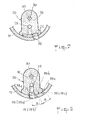
- this offset is obtained by the helical shape which has been given to the groove 22 of the dispenser, said groove covering at most only part of the holes 35 of a column, said holes being aligned on a generator 36.
- the offset is obtained by the combination of the straight shape of the groove 22 (parallel to the generatrices 36) and by the angular offset B of the alignment generators (39a, 39b, 39c) of the holes 35 of a column which, this time, are divided into three distinct groups.
- the groove 22 is in communication only with the holes 35 of only one of the three groups 38a, 38b, 38c of a column of superimposed sectors.
Abstract
Description
On connait déjà des filtres, notamment à huile moteur ou à carburant, munis de dispositifs de décolmatage.Filters are already known, in particular for engine oil or fuel, provided with unclogging devices.
Un tel filtre est constitué par un empilement de plusieurs éléments distincts de filtre assemblés les uns aux autres de manière à former un fourreau annulaire comportant au moins une face cylindrique, et, constitués,chaque élément de filtre, par plusieurs secteurs isolés les uns des autres, cependant que, d'une part, chaque élément de filtre est muni sur ses périphéries radiales externe et interne d'orifices de communication de chacun de ses secteurs avec lesdites périphéries, d'autre part, un distributeur de sectionnement est monté rotatif coaxialement à l'axe de ladite au moins une face cylindrique et comporte une chambre de sectionnement susceptible d'isoler un premier secteur d'un quelconque élément de filtre des autres secteurs dudit élément, en communiquant uniquement, à ce moment déterminé, avec ledit premier secteur au moyen d'un passage ménagé dans le distributeur et de l'orifice de communication dudit premier secteur.Such a filter is constituted by a stack of several distinct filter elements assembled together so as to form an annular sheath comprising at least one cylindrical face, and, constituted, each filter element, by several sectors isolated from each other , however, on the one hand, each filter element is provided on its external and internal radial peripheries with communication orifices of each of its sectors with said peripheries, on the other hand, a sectioning distributor is rotatably mounted coaxially with the axis of said at least one cylindrical face and comprises a sectioning chamber capable of isolating a first sector of any filter element from the other sectors of said element, by communicating only, at this determined moment, with said first sector at by means of a passage formed in the distributor and of the communication orifice of said first sector.
Dans ce filtre, le dispositif de décolmatage est constitué par la combinaison de la disposition des orifices de communication des éléments de filtre avec le passage du distributeur, qui permet aux tamis de filtration des premiers secteurs d'être traversés, à contre courant, par le fluide propre déjà filtré par les autres secteurs, et, ainsi d'être débarassés des impuretés qui s'y étaient préalablement déposées.In this filter, the unclogging device is constituted by the combination of the arrangement of the communication orifices of the filter elements with the passage of the distributor, which allows the filtration screens of the first sectors to be crossed, against the current, by the clean fluid already filtered by the other sectors, and thus to be rid of the impurities which had previously deposited there.
Le distributeur, entraîné en rotation isole donc à chaque rotation, au moins un secteur de chaque élément de filtre, et parfois davantage. Or, il faut observer qu'un secteur ainsi isolé est un secteur qui fonctionne pour se décolmater, et qui, par conséquent, ne participe pas à la filtration principale du produit à épurer.The distributor, driven in rotation therefore isolates at each rotation, at least one sector of each filter element, and sometimes more. However, it should be observed that a sector thus isolated is a sector which functions to decolmate, and which, consequently, does not take part in the main filtration of the product to be purified.
L'invention, dans un filtre tel que précédemment décrit, et en conservant un principe de décolmatage analogue, entend adapter celui-ci pour réduire le nombre de secteurs travaillant, à un moment donné, en décolmatage, et pour, en conséquence, augmenter corrélativement le nombre de secteurs participant à la filtration principale, et, par ce moyen, augmenter l'efficacité globale du filtre.The invention, in a filter as previously described, and while retaining a similar unclogging principle, intends to adapt it to reduce the number of working sectors, to at a given time, in unclogging, and for, consequently, correspondingly increasing the number of sectors participating in the main filtration, and, by this means, increasing the overall efficiency of the filter.
A cet effet, selon l'invention, la forme dudit passage et la disposition des orifices de communication susceptibles d'être situés en regard sont telles que les premiers secteurs de seulement une partie de la totalité des éléments de filtre sont, dans une position relative déterminée du distributeur par rapport à l'empilement des éléments de filtre, en communication avec ladite chambre de sectionnement.To this end, according to the invention, the shape of said passage and the arrangement of the communication orifices which may be located opposite are such that the first sectors of only part of all the filter elements are, in a relative position determined by the distributor with respect to the stack of filter elements, in communication with said sectioning chamber.
Les trois variantes de réalisation suivantes sont avantageuses, l'une ou l'autre d'entre elles étant de préférence adoptées :
- - le passage du distributeur est constitué par une rainure hélicoidale, cependant que les orifices de communication des premiers secteurs des éléments de filtre successifs sont alignés le long d'une génératrice de la face cylindrique du fourreau disposée en regard du distributeur ;
- - le passage du distributeur est constitué par une rainure droite s'étendant parallèlement à une génératrice de ladite face cylindrique du fourreau disposée en regard du distributeur, cependant que lesdits orifices de communication des premiers secteurs sont répartis en groupes distincts, les orifices de chaque groupe étant alignés le long d'une même génératrice de la face cylindrique du fourreau, et, les plans diamétraux contenant les génératrices d'alignement des orifices des divers groupes étant angulairement décalés les uns par rapport aux autres de manière à ne permettre la communication, à un moment déterminé, que des orifices d'un seul groupe d'orifices avec ledit passage du distributeur ;
- - le passage du distributeur est constitué par plusieurs rainures droites, distinctes les unes des autres, s'étendant parallèlement à une génératrice de ladite face cylindrique du fourreau disposée en regard du distributeur, chacune le long d'une partie seulement de la hauteur de l'empilement des éléments de filtre, cependant que, d'une part, les plans diamétraux contenant les rainures sont angulairement décalés les uns par rapport aux autres, d'autre part, les orifices de communication des premiers secteurs des éléments de filtres successifs sont alignés le long d'une génératrice de ladite face cylindrique du fourreau, de manière qu'à un moment déterminé une seule desdites rainures soit en communication avec seulement certains desdits orifices.
- - The passage of the distributor is constituted by a helical groove, while the communication orifices of the first sectors of the successive filter elements are aligned along a generatrix of the cylindrical face of the sheath disposed opposite the distributor;
- - The passage of the distributor is constituted by a straight groove extending parallel to a generator of said cylindrical face of the sheath disposed opposite the distributor, while said communication orifices of the first sectors are distributed in separate groups, the orifices of each group being aligned along the same generator of the cylindrical face of the sleeve, and, the diametrical planes containing the generators for aligning the orifices of the various groups being angularly offset with respect to each other so as not to allow communication, a determined moment, that orifices of a single group of orifices with said passage of the distributor;
- - The passage of the dispenser is constituted by several straight grooves, distinct from each other, extending parallel to a generator of said cylindrical face of the sheath disposed opposite the dispenser, each along a only part of the height of the stack of filter elements, while, on the one hand, the diametrical planes containing the grooves are angularly offset with respect to each other, on the other hand, the communication orifices of the first sectors successive filter elements are aligned along a generatrix of said cylindrical face of the sheath, so that at a given moment only one of said grooves is in communication with only some of said orifices.
L'avantage principal des filtres conformes à l'invention est de neutraliser pour la phase de décolmatage, un nombre de secteurs d'éléments de filtre sensiblement inférieur à ce qui était nécessaire auparavant. Autrement dit, en adoptant les dispositions de l'invention, on peut réaliser dans un encombrement déterminé un filtre ayant un meilleur rendement qu'auparavant, ou encore capable de traiter un volume de fluide à filtrer supérieur au volume traité par les filtres antérieurs.The main advantage of the filters according to the invention is to neutralize for the unclogging phase, a number of sectors of filter elements substantially lower than what was necessary before. In other words, by adopting the provisions of the invention, it is possible to produce, in a given space, a filter having a better efficiency than before, or even capable of treating a volume of fluid to be filtered greater than the volume treated by the previous filters.
Il convient d'observer, par ailleurs, que cette augmentation du rendement n'a pas été obtenue au détriment de la qualité de la filtration, car chaque élément de filtre est aussi bien décolmaté qu'antérieurement et conserve donc en permanence son aptitude à bien filtrer. La première économie n'a été réalisée qu'en affectant un volume de fluide de décolmatage moindre pour décolmater un nombre de secteurs d'éléments de filtre, moindre également.It should be noted, moreover, that this increase in yield was not obtained at the expense of the quality of the filtration, since each filter element is unclogged as well as previously and therefore permanently retains its ability to properly filter. The first saving was only achieved by allocating a smaller volume of unclogging fluid in order to unclog a smaller number of sectors of filter elements.
Si on tient compte, en outre, du fait que le fluide de décolmatage est généralement prélevé sur le fluide déjà filtré, on note l'obtention d'une deuxième économie, consistant à ne prélever qu'une quantité réduite de fluide déjà filtré aux fins de décolmatage.If we take into account, moreover, the fact that the unclogging fluid is generally taken from the already filtered fluid, we note obtaining a second economy, consisting in taking only a reduced quantity of fluid already filtered for the purposes unclogging.
L'invention sera mieux comprise, et des caractéristiques secondaires et leurs avantages apparaîtront au cours de la description de réalisations donnée ci-dessous à titre d'exemple.The invention will be better understood, and secondary characteristics and their advantages will appear during the description of embodiments given below by way of example.
Il est entendu que la description et les dessins ne sont donnés qu'à titre indicatif et non limitatif.It is understood that the description and the drawings are given for information only and are not limiting.
Il sera fait référence aux dessins annexés, dans lesquels :
- - la figure 1 est une coupe axiale d'un filtre conforme à l'invention ;
- - la figure 2 est une coupe suivant II-II de la figure 1 ;
- - la figure 3 est une vue développée des surfaces cylindriques du distributeur et de l'empilement des éléments de filtre en regard ;
- - la figure 4 est une coupe partielle d'un détail du distributeur des figures 1 et 2 ;
- - la figure 5 est une vue perspective du distributeur des figures 1 et 2 ;
- - la figure 6 est une vue développée des surfaces cylindriques en regard du distributeur et de l'empilement des éléments de filtre d'une deuxième réalisation conforme à l'invention ;
- - la figure 7 est une coupe partielle d'un détail du distributeur de la réalisation de la figure 6 ;
- - la figure 8 est une vue développée des surfaces cylindriques du distributeur et de l'empilement des éléments de filtre d'une troisième réalisation conforme à l'invention ; et,
- - la figure 9 est une coupe partielle d'un détail du distributeur de la réalisation de la figure 8.
- - Figure 1 is an axial section of a filter according to the invention;
- - Figure 2 is a section along II-II of Figure 1;
- - Figure 3 is a developed view of the cylindrical surfaces of the distributor and the stack of opposite filter elements;
- - Figure 4 is a partial section of a detail of the dispenser of Figures 1 and 2;
- - Figure 5 is a perspective view of the dispenser of Figures 1 and 2;
- - Figure 6 is a developed view of the cylindrical surfaces opposite the dispenser and the stack of filter elements of a second embodiment according to the invention;
- - Figure 7 is a partial section of a detail of the dispenser of the embodiment of Figure 6;
- - Figure 8 is a developed view of the cylindrical surfaces of the distributor and the stack of filter elements of a third embodiment according to the invention; and,
- FIG. 9 is a partial section of a detail of the dispenser of the embodiment of FIG. 8.
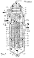
Le filtre des figures 1 et 2 comporte :
- - un corps de
filtre 1, muni d'un raccord d'admission 2 du fluide devant être filtré, d'un raccord d'évacuation 3 du fluide filtré par un empilement principal 4 d'éléments defiltration 5, et d'un raccord d'évacuation 6 du fluide de décolmatage des éléments defiltration 5, après filtration de ce fluide de décolmatage par un empilement secondaire 7 d'éléments de filtration 8, - - lesdits empilements principal 4 et secondaire 7, séparés par une pièce intermédiaire 9, qui est en appui sur un
épaulement 10, dont est muni lecorps 1, et qui ménage à l'intérieur dudit corps deux chambres principale 11 et secondaire 12 séparées avec étanchéité (13), la chambre principale 11 communiquant avec le raccord d'évacuation 3, - - un
alésage 14, commun aux deuxempilements 4 et 7, auquel est ajustée une bague intérieure 15, à l'intérieur de laquelle un distributeur rotatif 16 est monté, - - un moteur hydraulique 17, d'entraînement pas à pas du
distributeur 16, monté sur lecorps 1 et attelé par une tête d'entraînement 18 à une extrémité 19 dudistributeur 16, - - une gorge périphérique 20, ménagée dans le
distributeur 16, qui est en communication avec la chambre d'admission 21 du fluide devant être filtré, elle-même étant en communication avec le raccord d'admission 2, - - une rainure triple 22a, 22b, 22c qui est ménagée dans le
distributeur 16 et permet d'isoler un secteur angulaire 23 de quelques uns seulement (pas tous, comme cela sera expliqué ci-après)des éléments defiltration 5 de l'empilement principal 4 des autres secteurs angulaires 24 des mêmes éléments defiltration 5, - - un
conduit 25, interne audistributeur 16, avec lequel communique chaque rainure élémentaire 22a, 22b, 22c, et qui débouche dans la chambre secondaire 12, - - une
rainure 26, ménagée dans ledistributeur 16 et communiquant, d'une part, avec seulement un secteur angulaire 27 de chaque élément de filtration 8 de l'empilement secondaire 7, d'autre part, avec la chambre principale 11 par unconduit 28 ménagé dans la pièce intermédiaire 9, - - une gorge périphérique 29, ménagée dans le
distributeur 16, qui communique, par unconduit 30 interne audistributeur 16 avec une chambre supérieure 31 ménagée dans lecorps 1, - - des conduits d'alimentation 32 du
moteur 17, communiquant avec la chambre supérieure 31, - - le conduit d'échappement 33 du
moteur 17, communiquant avec le raccord d'évacuation 6, - - un conduit de liaison calibré (ayant une perte de charge déterminée) 34 reliant la chambre supérieure 31 au raccord d'évacuation 6.
- a
filter body 1, fitted with aninlet connection 2 for the fluid to be filtered, with anoutlet connection 3 for the fluid filtered by amain stack 4 offiltration elements 5, and with afitting evacuation 6 of the unclogging fluid from thefiltration elements 5, after filtration of this unclogging fluid by a secondary stack 7 of filtration elements 8, - - Said main 4 and secondary 7 stacks, separated by an
intermediate piece 9, which is supported on ashoulder 10, which is provided with thebody 1, and which provides inside said body twomain chambers 11 and secondary 12 separated with sealing (13), themain chamber 11 communicating with theevacuation connector 3, - a
bore 14, common to the twostacks 4 and 7, to which aninner ring 15 is fitted, inside which arotary distributor 16 is mounted, - a
hydraulic motor 17, step by step drive of thedistributor 16, mounted on thebody 1 and coupled by a drive head 18 to one end 19 of thedistributor 16, - a
peripheral groove 20, formed in thedistributor 16, which is in communication with theinlet chamber 21 of the fluid to be filtered, itself being in communication with theinlet connector 2, - - A
triple groove distributor 16 and makes it possible to isolate anangular sector 23 from only a few (not all, as will be explained below) of thefiltration elements 5 of the stack main 4 of the otherangular sectors 24 of thesame filtration elements 5, - a
conduit 25, internal to thedistributor 16, with which each elementary groove 22a, 22b, 22c communicates, and which opens into thesecondary chamber 12, - - A
groove 26, formed in thedistributor 16 and communicating, on the one hand, with only anangular sector 27 of each filtration element 8 of the secondary stack 7, on the other hand, with themain chamber 11 by aconduit 28 formed in theintermediate part 9, - a
peripheral groove 29, formed in thedistributor 16, which communicates, via aconduit 30 internal to thedistributor 16 with an upper chamber 31 formed in thebody 1, -
supply conduits 32 of themotor 17, communicating with the upper chamber 31, - the
exhaust duct 33 of theengine 17, communicating with theexhaust connector 6, - - a calibrated connecting pipe (having a determined pressure drop) 34 connecting the upper chamber 31 to the
fitting evacuation 6.
De manière classique, la bague 15, dont on voit une vue développée sur la figure 3, superposée à une vue de la face du distributeur 16 disposée en regard, comporte des trous traversant 35, qui dans la réalisation des figures 1 à 5 sont alignés sur des génératrices 36 de la bague 15 et correspondent aux orifices de la périphérie interne de l'empilement principal 4. Cet empilement 4 comporte également des orifices ménagés sur sa périphérie externe, ces orifices des périphéries interne et externe étant séparés par les tamis des éléments filtrants.Conventionally, the
La structure de l'empilement secondaire 7 est analogue, avec orifices sur les périphéries interne et externe séparés par les tamis de filtration.The structure of the secondary stack 7 is similar, with orifices on the internal and external peripheries separated by the filtration screens.
De manière connue, le fluide devant être filtré, admis dans la chambre d'admission 21, parvient dans la gorge 20 du distributeur, passe à travers les orifices de la périphérie interne des secteurs 24 des éléments de filtration 5 qui sont en regard de la gorge 20, puis à travers les trous correspondant 35 de la bague 15, traversent les tamis, puis les orifices de la périphérie externe des mêmes secteurs, et ressort filtré dans la chambre principale 11, pour ensuite être évacué à travers le raccord d'évacuation 3.In known manner, the fluid to be filtered, admitted into the
Cependant, une partie du fluide filtré contenu dans la chambre principale 11 traverse, en sens inverse du précédent, de la périphérie externe vers la périphérie interne de l'empilement 4 ceux des secteurs 23 des éléments de filtration 5 qui sont disposés en regard de l'une des rainures 22a, 22b, 22c (en fait, la rainure 22a dans la configuration de la figure 3). Cette faible partie de fluide filtré permet de dégager des tamis desdits secteurs 23 les impuretés qui s'y étaient préalablement déposées et ainsi, en nettoyant ces tamis, de les rendre de nouveau aptes à une filtration efficace. Cette partie du fluide, qui traverse les tamis des secteurs 23 est collectée par la rainure disposée en regard de ces secteurs (22a de la figure 3) et dirigé, par le conduit 25 vers la chambre secondaire 12.However, part of the filtered fluid contained in the
Le fluide chargé d'impuretés, contenu dans la chambre secondaire 12 traverse, de la périphérie externe vers la périphérie interne des secteurs des éléments de filtration de l'empilement, qui sont en regard de la gorge 29 du distributeur 16, et, filtré par les tamis desdits secteurs, de la gorge 29 est dirigé par le conduit 30, la chambre 31 et le conduit 34, vers le raccord d'évacuation 6 pour une nouvelle utilisation. A noter que, de manière également connue, une partie de ce fluide filtré contenu dans la chambre supérieure 31 est utilisée en tant que fluide d'alimentation du moteur 17 (conduits 32).The fluid charged with impurities, contained in the
La nouveauté réside dans le fait que pendant l'opération de "décolmatage" des tamis des éléments de filtration 5 de l'empilement principal 4, les secteurs 23 d'une seule colonne sont lavés de leurs impuretés, et en fait, parmi les secteurs 23 d'une colonne, seuls sont traversés par le fluide de "lavage" les secteurs des éléments dont les trous 35 sont en communication avec une rainure 22a, 22b, 22c. Or, comme cela est visible sur la figure 4, chacune de ses rainures est droite (parallèle à une génératrice de la bague 15 disposée en regard), parallèle aux génératrices 36 d'alignement des trous 35 d'une colonne de secteurs 23 ou 24, et est décalée angulairement, par rapport à l'axe 37 de rotation du distributeur 16, d'un angle A par rapport à la rainure adjacente, de manière qu'avec un distributeur 16 à trois rainures distinctes 22a, 22b, 22c, comme celui des figures 1 à 5, seulement un tiers des trous 35 sont disposés en regard desdites rainures, pendant l'opération de "lavage/décolmatage". Ainsi, seulement un tiers des secteurs 23 d'une colonne est traversé par le fluide de lavage à un moment donné. Bien entendu, à la prochaine rotation du distributeur, ce seront les secteurs 23 du tiers suivant des éléments de filtration qui seront alors en communication avec la rainure 22b. Puis, après la rainure 22b, ce sera la rainure 22c qui, à la suite d'une nouvelle rotation du distributeur 16, permettra le décolmatage des secteurs 23 correspondant. Il n'y a qu'un tiers seulement des secteurs d'une seule colonne qui, à un moment donné, peut être décolmaté.The novelty lies in the fact that during the "unclogging" operation of the sieves of the
Bien entendu, avec la nouvelle disposition préconisée, le débit de fluide de décolmatage est, pour la même efficacité de décolmatage, le tiers du débit qui était nécessaire auparavant, lorsque le décolmatage était celui de tous les secteurs d'une même colonne d'éléments de filtration. On ne consomme donc plus que le tiers du débit antérieurement consommé. Or, ce débit étant prélevé dans la chambre principale 11, doit être déduit du débit de fluide filtré effectivement utilisable, pouvant être évacué à travers le raccord 3. Ceci conduit à constater que le fluide utilisé pour le décolmatage constitue, en quelque sorte, une perte de fluide filtré. Dans le cas de la réalisation nouvelle, cette perte a été divisée par trois, ce qui est considérable.Of course, with the new recommended arrangement, the flow of unclogging fluid is, for the same unclogging efficiency, a third of the flow which was necessary previously, when the unclogging was that of all the sectors of the same column of elements filtration. We therefore only consume a third of the flow previously consumed. However, this flow being taken from the
En outre, à un instant déterminé, tous les secteurs de tous les éléments de filtration 5 de l'empilement principal 4 sont actifs pour épurer le fluide à filtrer, sauf les quelques secteurs 23 qui sont en phase de décolmatage. L'invention, en réduisant le nombre des secteurs 23 en phase de décolmatage, laisse disponibles pour la filtration tous les autres secteurs. Ainsi, de ce deuxième point de vue, un filtre complet d'un encombrement donné peut, selon la nouvelle conception préconisée, traiter un débit de fluide devant être épuré supérieur au débit que pouvait traiter un filtre complet classique. Sur ce point, il y a donc également gain d'efficacité.In addition, at a determined instant, all the sectors of all the
Le même principe du décolmatage simultané de seulement quelques secteurs d'une colonne de secteurs d'éléments de filtration peut être apppliqué à d'autres réalisations que celles des figures 1 à 5. Deux telles autres réalisations sont représentées sur les figures 6 et 7, d'une part, 8 et 9, d'autre part. Il s'agit, dans chaque réalisation, de réaliser un décalage entre les trous 35 et la rainure du distributeur 16.The same principle of the simultaneous unclogging of only a few sectors of a column of sectors of filtration elements can be applied to other embodiments than those of FIGS. 1 to 5. Two such other embodiments are shown in FIGS. 6 and 7, on the one hand, 8 and 9, on the other hand. It is a question, in each embodiment, of making an offset between the
Dans la réalisation des figures 6 et 7, ce décalage est obtenu par la forme hélicoidale qui a été donnée à la rainure 22 du distributeur, ladite rainure ne recouvrant au plus qu'une partie des trous 35 d'une colonne, lesdits trous étant alignés sur une génératrice 36.In the embodiment of Figures 6 and 7, this offset is obtained by the helical shape which has been given to the
Dans la réalisation des figures 8 et 9, le décalage est obtenu par la combinaison de la forme droite de la rainure 22 (parallèle aux génératrices 36) et par le décalage angulaire B des génératrices d'alignement (39a, 39b, 39c) des trous 35 d'une colonne qui, cette fois, sont répartis en trois groupes distincts. A un moment donné, la rainure 22 n'est en communication qu'avec les trous 35 d'un seul des trois groupes 38a, 38b, 38c d'une colonne de secteurs superposés.In the embodiment of FIGS. 8 and 9, the offset is obtained by the combination of the straight shape of the groove 22 (parallel to the generatrices 36) and by the angular offset B of the alignment generators (39a, 39b, 39c) of the
Dans chacune de ces deux réalisations, on retrouve évidemment le même fonctionnement et les mêmes avantages que ce qui a été exposé à propos de la réalisation des figures 1 à 5.In each of these two embodiments, there is obviously the same operation and the same advantages as what has been explained in connection with the embodiment of FIGS. 1 to 5.
L'invention n'est, au reste, pas limitée aux réalisations représentées, mais en couvre au contraire toutes les variantes qui pourraient leur être apportées sans sortir de leur cadre, ni de leur esprit.The invention is, moreover, not limited to the embodiments shown, but on the contrary covers all the variants which could be made to them without departing from their scope or their spirit.
Claims (4)
Priority Applications (1)
| Application Number | Priority Date | Filing Date | Title |
|---|---|---|---|
| AT84401581T ATE22815T1 (en) | 1983-08-08 | 1984-07-27 | EQUIP THE FILTERS WITH A CLEANING DEVICE. |
Applications Claiming Priority (2)
| Application Number | Priority Date | Filing Date | Title |
|---|---|---|---|
| FR8313043 | 1983-08-08 | ||
| FR8313043A FR2550463B1 (en) | 1983-08-08 | 1983-08-08 | FILTER PROVIDED WITH A CLEANING DEVICE |
Publications (2)
| Publication Number | Publication Date |
|---|---|
| EP0136202A1 true EP0136202A1 (en) | 1985-04-03 |
| EP0136202B1 EP0136202B1 (en) | 1986-10-15 |
Family
ID=9291485
Family Applications (1)
| Application Number | Title | Priority Date | Filing Date |
|---|---|---|---|
| EP84401581A Expired EP0136202B1 (en) | 1983-08-08 | 1984-07-27 | Filter provided with a cleaning device |
Country Status (10)
| Country | Link |
|---|---|
| US (1) | US4601826A (en) |
| EP (1) | EP0136202B1 (en) |
| JP (1) | JPS60106509A (en) |
| AT (1) | ATE22815T1 (en) |
| CA (1) | CA1236031A (en) |
| DE (1) | DE3460937D1 (en) |
| ES (1) | ES289774Y (en) |
| FI (1) | FI73891C (en) |
| FR (1) | FR2550463B1 (en) |
| IN (1) | IN161498B (en) |
Cited By (4)
| Publication number | Priority date | Publication date | Assignee | Title |
|---|---|---|---|---|
| FR2725917A1 (en) * | 1994-10-19 | 1996-04-26 | Moatti Filtration | ASSEMBLY FOR TREATING A FLUID BY FILTRATION AND CENTRIFUGATION |
| WO1996023590A1 (en) * | 1995-02-02 | 1996-08-08 | The Glacier Metal Company Limited | Liquid cleaning system including back-flushing filter and centrifugal cleaner therefor |
| WO2000061923A1 (en) * | 1999-04-12 | 2000-10-19 | Filterwerk Mann+Hummel Gmbh | Liquid cleaning arrangement |
| US7947302B2 (en) | 2005-08-31 | 2011-05-24 | Cordis Corporation | Antithrombotic coating for drug eluting medical devices |
Families Citing this family (8)
| Publication number | Priority date | Publication date | Assignee | Title |
|---|---|---|---|---|
| DE8502177U1 (en) * | 1985-01-28 | 1985-08-08 | Kemmelmeyer, Werner H., 8201 Rohrdorf | Filter device in segment design |
| IL93160A (en) * | 1990-01-24 | 1992-12-01 | Rosenberg Peretz | Back-flushable filter |
| FR2964329B1 (en) * | 2010-09-03 | 2012-09-28 | Alfa Laval Moatti | AUTOMATIC CLEANING FILTER |
| DE202014104200U1 (en) * | 2014-06-11 | 2015-09-14 | Boll & Kirch Filterbau Gmbh | Backwash filter and filter insert for this |
| DE102017002646A1 (en) * | 2017-03-18 | 2018-09-20 | Hydac Process Technology Gmbh | filter means |
| ES2914980T3 (en) * | 2019-08-19 | 2022-06-20 | Alfa Laval Moatti | Filter unit with improved cover assembly |
| KR102183820B1 (en) * | 2020-03-10 | 2020-11-30 | 주식회사 그레넥스 | Back wash device for fabric filtration apparatus |
| CN112554992A (en) * | 2020-11-04 | 2021-03-26 | 李冬菊 | Filter for purifying automobile engine oil |
Citations (4)
| Publication number | Priority date | Publication date | Assignee | Title |
|---|---|---|---|---|
| FR2120940A5 (en) * | 1970-12-28 | 1972-08-18 | Kanagawa Kiki Kogyo Co Ltd | |
| FR2138238A1 (en) * | 1971-05-19 | 1973-01-05 | Moatti Georges | |
| FR2143694A1 (en) * | 1971-06-30 | 1973-02-09 | Kanagawa Kiki Kogyo Co Ltd | |
| FR2181510A2 (en) * | 1972-04-26 | 1973-12-07 | Moatti Georges |
Family Cites Families (6)
| Publication number | Priority date | Publication date | Assignee | Title |
|---|---|---|---|---|
| US2799397A (en) * | 1952-12-31 | 1957-07-16 | Berline Raoul | Pressure filters |
| US3985656A (en) * | 1974-04-29 | 1976-10-12 | Kostas Savas Arvanitakis | Filter cleaning apparatus |
| FI54060C (en) * | 1976-09-14 | 1978-10-10 | Rauma Repola Oy | SKIVFILTER |
| FR2460398A1 (en) * | 1979-07-02 | 1981-01-23 | Moatti Georges | HYDRAULIC MOTOR |
| US4330405A (en) * | 1980-09-29 | 1982-05-18 | Davis Kent L | Vacuum disc filter |
| DE3131281C2 (en) * | 1981-08-07 | 1993-10-21 | Fluidtech Gmbh | Device for carrying two streams separately, optionally only one stream, at least one medium |
-
1983
- 1983-08-08 FR FR8313043A patent/FR2550463B1/en not_active Expired
-
1984
- 1984-07-27 AT AT84401581T patent/ATE22815T1/en not_active IP Right Cessation
- 1984-07-27 DE DE8484401581T patent/DE3460937D1/en not_active Expired
- 1984-07-27 EP EP84401581A patent/EP0136202B1/en not_active Expired
- 1984-07-30 US US06/636,100 patent/US4601826A/en not_active Expired - Lifetime
- 1984-07-30 IN IN617/DEL/84A patent/IN161498B/en unknown
- 1984-08-03 CA CA000460366A patent/CA1236031A/en not_active Expired
- 1984-08-07 ES ES1984289774U patent/ES289774Y/en not_active Expired
- 1984-08-07 FI FI843105A patent/FI73891C/en not_active IP Right Cessation
- 1984-08-08 JP JP59165016A patent/JPS60106509A/en active Granted
Patent Citations (4)
| Publication number | Priority date | Publication date | Assignee | Title |
|---|---|---|---|---|
| FR2120940A5 (en) * | 1970-12-28 | 1972-08-18 | Kanagawa Kiki Kogyo Co Ltd | |
| FR2138238A1 (en) * | 1971-05-19 | 1973-01-05 | Moatti Georges | |
| FR2143694A1 (en) * | 1971-06-30 | 1973-02-09 | Kanagawa Kiki Kogyo Co Ltd | |
| FR2181510A2 (en) * | 1972-04-26 | 1973-12-07 | Moatti Georges |
Cited By (7)
| Publication number | Priority date | Publication date | Assignee | Title |
|---|---|---|---|---|
| FR2725917A1 (en) * | 1994-10-19 | 1996-04-26 | Moatti Filtration | ASSEMBLY FOR TREATING A FLUID BY FILTRATION AND CENTRIFUGATION |
| WO1996012549A1 (en) * | 1994-10-19 | 1996-05-02 | Alfa Laval Moatti Snc | Assembly for processing a fluid by filtration and centrifugation |
| US5674392A (en) * | 1994-10-19 | 1997-10-07 | Moatti Filtration S.A. | Treatment assembly for treating a fluid by filtering and centrifuging |
| WO1996023590A1 (en) * | 1995-02-02 | 1996-08-08 | The Glacier Metal Company Limited | Liquid cleaning system including back-flushing filter and centrifugal cleaner therefor |
| US5906733A (en) * | 1995-02-02 | 1999-05-25 | The Glacier Metal Company Limited | Liquid cleaning system including back-flushing filter and centrifugal cleaner therefor |
| WO2000061923A1 (en) * | 1999-04-12 | 2000-10-19 | Filterwerk Mann+Hummel Gmbh | Liquid cleaning arrangement |
| US7947302B2 (en) | 2005-08-31 | 2011-05-24 | Cordis Corporation | Antithrombotic coating for drug eluting medical devices |
Also Published As
| Publication number | Publication date |
|---|---|
| FR2550463A1 (en) | 1985-02-15 |
| FI73891B (en) | 1987-08-31 |
| US4601826A (en) | 1986-07-22 |
| ATE22815T1 (en) | 1986-11-15 |
| ES289774Y (en) | 1986-10-16 |
| FI843105A0 (en) | 1984-08-07 |
| CA1236031A (en) | 1988-05-03 |
| JPH0128605B2 (en) | 1989-06-05 |
| FI843105A (en) | 1985-02-09 |
| IN161498B (en) | 1987-12-12 |
| FI73891C (en) | 1987-12-10 |
| DE3460937D1 (en) | 1986-11-20 |
| EP0136202B1 (en) | 1986-10-15 |
| ES289774U (en) | 1986-03-01 |
| JPS60106509A (en) | 1985-06-12 |
| FR2550463B1 (en) | 1985-12-06 |
Similar Documents
| Publication | Publication Date | Title |
|---|---|---|
| EP0145552B1 (en) | Filter with two distinct filtering stacks | |
| EP0136202B1 (en) | Filter provided with a cleaning device | |
| EP0062549A2 (en) | Apparatus for filtering fluids and process carried out in this apparatus | |
| EP0108665B1 (en) | Fluid filter | |
| EP0057670A2 (en) | Disc filter for liquids | |
| CH433194A (en) | Continuous automatic cleaning multicellular mechanical filtration device for liquids under pressure | |
| EP0734751A1 (en) | Cyclone separator with coalescence element | |
| EP2980405B1 (en) | Distribution device for a hydraulic machine | |
| FR2611816A1 (en) | PRESSURIZED FLUID MECHANISM, ENGINE OR PUMP, MULTIPLE CYLINDER | |
| FR2677893A1 (en) | FLUID FILTER COMPRISING TWO FILTRATION ASSEMBLIES. | |
| EP0149931B1 (en) | Filter comprising several reception chambers for the filtrate and for another liquid issuing from the residue of the principal filtration | |
| FR3038348B1 (en) | HYDRAULIC MACHINE WITH RADIAL PISTONS WITH HARMONIC DISTRIBUTION | |
| FR2624795A1 (en) | DEVICE FOR RECEIVING A COMBINATION OF TWO VARIABLE VOLUME CHAMBERS AND A PLURALITY OF VALVES FOR A POWER SUPPLY CIRCUIT OF AN INKJET PRINTING HEAD | |
| FR2514411A1 (en) | METHOD AND EQUIPMENT FOR REGENERATING LUBRICATING OILS IN OPERATION | |
| FR2637944A1 (en) | 2-CYLINDER PRESSURIZED FLUID MECHANISM AND CLOSED CIRCUIT USING THE SAME | |
| EP1466092A1 (en) | Hydraulic radial piston motor | |
| EP0053559A1 (en) | Distribution device, particularly for a servo-steering system | |
| EP0607069B1 (en) | Hydraulic motor piston | |
| FR2797197A1 (en) | Casing for stack of filter discs has two containers with co=operating central opening(s) and element(s) respectively | |
| FR2507681A1 (en) | ||
| FR2645913A1 (en) | DEVICE FOR TRANSFERRING FUEL FROM A TANK TO AN INTERNAL COMBUSTION ENGINE, IN PARTICULAR A MOTOR VEHICLE | |
| FR2474102A1 (en) | FUEL INJECTION PUMP | |
| FR2520445A1 (en) | FUEL INJECTOR | |
| FR2505203A1 (en) | FILTERING DEVICE FOR SEPARATING SOLID PARTICLES FROM A LIQUID | |
| EP0077263B1 (en) | Rotary hydraulic distributor |
Legal Events
| Date | Code | Title | Description |
|---|---|---|---|
| PUAI | Public reference made under article 153(3) epc to a published international application that has entered the european phase |
Free format text: ORIGINAL CODE: 0009012 |
|
| AK | Designated contracting states |
Designated state(s): AT BE CH DE GB IT LI NL SE |
|
| 17P | Request for examination filed |
Effective date: 19850401 |
|
| GRAA | (expected) grant |
Free format text: ORIGINAL CODE: 0009210 |
|
| AK | Designated contracting states |
Kind code of ref document: B1 Designated state(s): AT BE CH DE GB IT LI NL SE |
|
| REF | Corresponds to: |
Ref document number: 22815 Country of ref document: AT Date of ref document: 19861115 Kind code of ref document: T |
|
| ITF | It: translation for a ep patent filed |
Owner name: JACOBACCI & PERANI S.P.A. |
|
| REF | Corresponds to: |
Ref document number: 3460937 Country of ref document: DE Date of ref document: 19861120 |
|
| PLBE | No opposition filed within time limit |
Free format text: ORIGINAL CODE: 0009261 |
|
| STAA | Information on the status of an ep patent application or granted ep patent |
Free format text: STATUS: NO OPPOSITION FILED WITHIN TIME LIMIT |
|
| 26N | No opposition filed | ||
| ITTA | It: last paid annual fee | ||
| EAL | Se: european patent in force in sweden |
Ref document number: 84401581.8 |
|
| NLT1 | Nl: modifications of names registered in virtue of documents presented to the patent office pursuant to art. 16 a, paragraph 1 |
Owner name: ALFA LAVAL MOATTI SNC;MOATTI FILTRATION S.A. |
|
| REG | Reference to a national code |
Ref country code: CH Ref legal event code: PUE Owner name: GEORGES MOATTI, SOCIETE ANONYME TRANSFER- ALFA LAV |
|
| BECN | Be: change of holder's name |
Effective date: 19970121 |
|
| REG | Reference to a national code |
Ref country code: GB Ref legal event code: IF02 |
|
| PGFP | Annual fee paid to national office [announced via postgrant information from national office to epo] |
Ref country code: NL Payment date: 20020618 Year of fee payment: 19 |
|
| PGFP | Annual fee paid to national office [announced via postgrant information from national office to epo] |
Ref country code: SE Payment date: 20020619 Year of fee payment: 19 Ref country code: AT Payment date: 20020619 Year of fee payment: 19 |
|
| PGFP | Annual fee paid to national office [announced via postgrant information from national office to epo] |
Ref country code: CH Payment date: 20020711 Year of fee payment: 19 |
|
| PGFP | Annual fee paid to national office [announced via postgrant information from national office to epo] |
Ref country code: GB Payment date: 20020719 Year of fee payment: 19 |
|
| PGFP | Annual fee paid to national office [announced via postgrant information from national office to epo] |
Ref country code: BE Payment date: 20020805 Year of fee payment: 19 |
|
| PGFP | Annual fee paid to national office [announced via postgrant information from national office to epo] |
Ref country code: DE Payment date: 20030708 Year of fee payment: 20 |
|
| PG25 | Lapsed in a contracting state [announced via postgrant information from national office to epo] |
Ref country code: GB Free format text: LAPSE BECAUSE OF NON-PAYMENT OF DUE FEES Effective date: 20030727 Ref country code: AT Free format text: LAPSE BECAUSE OF NON-PAYMENT OF DUE FEES Effective date: 20030727 |
|
| PG25 | Lapsed in a contracting state [announced via postgrant information from national office to epo] |
Ref country code: SE Free format text: LAPSE BECAUSE OF NON-PAYMENT OF DUE FEES Effective date: 20030728 |
|
| PG25 | Lapsed in a contracting state [announced via postgrant information from national office to epo] |
Ref country code: LI Free format text: LAPSE BECAUSE OF NON-PAYMENT OF DUE FEES Effective date: 20030731 Ref country code: CH Free format text: LAPSE BECAUSE OF NON-PAYMENT OF DUE FEES Effective date: 20030731 Ref country code: BE Free format text: LAPSE BECAUSE OF NON-PAYMENT OF DUE FEES Effective date: 20030731 |
|
| BERE | Be: lapsed |
Owner name: *ALFA LAVAL MOATTI SNC Effective date: 20030731 |
|
| PG25 | Lapsed in a contracting state [announced via postgrant information from national office to epo] |
Ref country code: NL Free format text: LAPSE BECAUSE OF NON-PAYMENT OF DUE FEES Effective date: 20040201 |
|
| EUG | Se: european patent has lapsed | ||
| REG | Reference to a national code |
Ref country code: CH Ref legal event code: PL |
|
| GBPC | Gb: european patent ceased through non-payment of renewal fee |
Effective date: 20030727 |
|
| NLV4 | Nl: lapsed or anulled due to non-payment of the annual fee |
Effective date: 20040201 |