EP0136202A1 - Filter mit einer Reinigungseinrichtung versehen - Google Patents
Filter mit einer Reinigungseinrichtung versehen Download PDFInfo
- Publication number
- EP0136202A1 EP0136202A1 EP84401581A EP84401581A EP0136202A1 EP 0136202 A1 EP0136202 A1 EP 0136202A1 EP 84401581 A EP84401581 A EP 84401581A EP 84401581 A EP84401581 A EP 84401581A EP 0136202 A1 EP0136202 A1 EP 0136202A1
- Authority
- EP
- European Patent Office
- Prior art keywords
- orifices
- sectors
- distributor
- communication
- filter
- Prior art date
- Legal status (The legal status is an assumption and is not a legal conclusion. Google has not performed a legal analysis and makes no representation as to the accuracy of the status listed.)
- Granted
Links
- 238000004140 cleaning Methods 0.000 title description 2
- 238000002955 isolation Methods 0.000 abstract 1
- 238000004519 manufacturing process Methods 0.000 abstract 1
- 238000001914 filtration Methods 0.000 description 27
- 239000012530 fluid Substances 0.000 description 26
- 208000031968 Cadaver Diseases 0.000 description 5
- 239000012535 impurity Substances 0.000 description 4
- 238000005406 washing Methods 0.000 description 3
- 230000002093 peripheral effect Effects 0.000 description 2
- 239000000446 fuel Substances 0.000 description 1
- 239000010705 motor oil Substances 0.000 description 1
- 238000007789 sealing Methods 0.000 description 1
Images


Classifications
-
- B—PERFORMING OPERATIONS; TRANSPORTING
- B01—PHYSICAL OR CHEMICAL PROCESSES OR APPARATUS IN GENERAL
- B01D—SEPARATION
- B01D29/00—Filters with filtering elements stationary during filtration, e.g. pressure or suction filters, not covered by groups B01D24/00 - B01D27/00; Filtering elements therefor
- B01D29/39—Filters with filtering elements stationary during filtration, e.g. pressure or suction filters, not covered by groups B01D24/00 - B01D27/00; Filtering elements therefor with hollow discs side by side on, or around, one or more tubes, e.g. of the leaf type
- B01D29/41—Filters with filtering elements stationary during filtration, e.g. pressure or suction filters, not covered by groups B01D24/00 - B01D27/00; Filtering elements therefor with hollow discs side by side on, or around, one or more tubes, e.g. of the leaf type mounted transversely on the tube
- B01D29/413—Filters with filtering elements stationary during filtration, e.g. pressure or suction filters, not covered by groups B01D24/00 - B01D27/00; Filtering elements therefor with hollow discs side by side on, or around, one or more tubes, e.g. of the leaf type mounted transversely on the tube divided in sectors
-
- B—PERFORMING OPERATIONS; TRANSPORTING
- B01—PHYSICAL OR CHEMICAL PROCESSES OR APPARATUS IN GENERAL
- B01D—SEPARATION
- B01D29/00—Filters with filtering elements stationary during filtration, e.g. pressure or suction filters, not covered by groups B01D24/00 - B01D27/00; Filtering elements therefor
- B01D29/50—Filters with filtering elements stationary during filtration, e.g. pressure or suction filters, not covered by groups B01D24/00 - B01D27/00; Filtering elements therefor with multiple filtering elements, characterised by their mutual disposition
- B01D29/52—Filters with filtering elements stationary during filtration, e.g. pressure or suction filters, not covered by groups B01D24/00 - B01D27/00; Filtering elements therefor with multiple filtering elements, characterised by their mutual disposition in parallel connection
- B01D29/54—Filters with filtering elements stationary during filtration, e.g. pressure or suction filters, not covered by groups B01D24/00 - B01D27/00; Filtering elements therefor with multiple filtering elements, characterised by their mutual disposition in parallel connection arranged concentrically or coaxially
-
- B—PERFORMING OPERATIONS; TRANSPORTING
- B01—PHYSICAL OR CHEMICAL PROCESSES OR APPARATUS IN GENERAL
- B01D—SEPARATION
- B01D29/00—Filters with filtering elements stationary during filtration, e.g. pressure or suction filters, not covered by groups B01D24/00 - B01D27/00; Filtering elements therefor
- B01D29/62—Regenerating the filter material in the filter
- B01D29/66—Regenerating the filter material in the filter by flushing, e.g. counter-current air-bumps
- B01D29/68—Regenerating the filter material in the filter by flushing, e.g. counter-current air-bumps with backwash arms, shoes or nozzles
- B01D29/682—Regenerating the filter material in the filter by flushing, e.g. counter-current air-bumps with backwash arms, shoes or nozzles with a rotary movement with respect to the filtering element
-
- F—MECHANICAL ENGINEERING; LIGHTING; HEATING; WEAPONS; BLASTING
- F01—MACHINES OR ENGINES IN GENERAL; ENGINE PLANTS IN GENERAL; STEAM ENGINES
- F01M—LUBRICATING OF MACHINES OR ENGINES IN GENERAL; LUBRICATING INTERNAL COMBUSTION ENGINES; CRANKCASE VENTILATING
- F01M1/00—Pressure lubrication
- F01M1/10—Lubricating systems characterised by the provision therein of lubricant venting or purifying means, e.g. of filters
- F01M2001/1007—Lubricating systems characterised by the provision therein of lubricant venting or purifying means, e.g. of filters characterised by the purification means combined with other functions
- F01M2001/1021—Lubricating systems characterised by the provision therein of lubricant venting or purifying means, e.g. of filters characterised by the purification means combined with other functions comprising self cleaning systems
Definitions
- Filters are already known, in particular for engine oil or fuel, provided with unclogging devices.
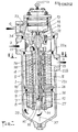
- Such a filter is constituted by a stack of several distinct filter elements assembled together so as to form an annular sheath comprising at least one cylindrical face, and, constituted, each filter element, by several sectors isolated from each other , however, on the one hand, each filter element is provided on its external and internal radial peripheries with communication orifices of each of its sectors with said peripheries, on the other hand, a sectioning distributor is rotatably mounted coaxially with the axis of said at least one cylindrical face and comprises a sectioning chamber capable of isolating a first sector of any filter element from the other sectors of said element, by communicating only, at this determined moment, with said first sector at by means of a passage formed in the distributor and of the communication orifice of said first sector.
- the unclogging device is constituted by the combination of the arrangement of the communication orifices of the filter elements with the passage of the distributor, which allows the filtration screens of the first sectors to be crossed, against the current, by the clean fluid already filtered by the other sectors, and thus to be rid of the impurities which had previously deposited there.
- the distributor driven in rotation therefore isolates at each rotation, at least one sector of each filter element, and sometimes more.
- a sector thus isolated is a sector which functions to decolmate, and which, consequently, does not take part in the main filtration of the product to be purified.
- the invention in a filter as previously described, and while retaining a similar unclogging principle, intends to adapt it to reduce the number of working sectors, to at a given time, in unclogging, and for, consequently, correspondingly increasing the number of sectors participating in the main filtration, and, by this means, increasing the overall efficiency of the filter.
- the shape of said passage and the arrangement of the communication orifices which may be located opposite are such that the first sectors of only part of all the filter elements are, in a relative position determined by the distributor with respect to the stack of filter elements, in communication with said sectioning chamber.
- the main advantage of the filters according to the invention is to neutralize for the unclogging phase, a number of sectors of filter elements substantially lower than what was necessary before.
- it is possible to produce, in a given space, a filter having a better efficiency than before, or even capable of treating a volume of fluid to be filtered greater than the volume treated by the previous filters.
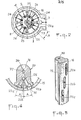
- the ring 15 a view of which can be seen developed in FIG. 3, superimposed on a view of the face of the distributor 16 arranged opposite, has through holes 35, which in the embodiment of FIGS. 1 to 5 are aligned on generatrices 36 of the ring 15 and correspond to the orifices of the internal periphery of the main stack 4.
- This stack 4 also has orifices formed on its external periphery, these orifices of the internal and external peripheries being separated by the sieves of the elements filters.
- the structure of the secondary stack 7 is similar, with orifices on the internal and external peripheries separated by the filtration screens.
- the fluid to be filtered admitted into the inlet chamber 21, reaches the groove 20 of the distributor, passes through the orifices of the internal periphery of the sectors 24 of the filter elements 5 which are opposite the groove 20, then through the corresponding holes 35 of the ring 15, pass through the screens, then the orifices of the external periphery of the same sectors, and filtered spring in the main chamber 11, to then be evacuated through the evacuation connector 3.
- part of the filtered fluid contained in the main chamber 11 passes, in the opposite direction to the previous one, from the external periphery towards the internal periphery of the stack 4, those of the sectors 23 of the filtration elements 5 which are arranged opposite the 'one of the grooves 22a, 22b, 22c (in fact, the groove 22a in the configuration of Figure 3).
- This small portion of filtered fluid makes it possible to free from the sieves of said sectors 23 the impurities which had previously deposited therein and thus, by cleaning these sieves, to make them again suitable for effective filtration.
- This part of the fluid, which passes through the sieves of the sectors 23 is collected by the groove arranged opposite these sectors (22a of FIG. 3) and directed, through the conduit 25 towards the secondary chamber 12.
- the fluid charged with impurities, contained in the secondary chamber 12 passes through, from the external periphery towards the internal periphery of the sectors of the filtration elements of the stack, which are opposite the groove 29 of the distributor 16, and, filtered by the sieves of said sectors, from the groove 29 is directed by the conduit 30, the chamber 31 and the conduit 34, towards the discharge connector 6 for new use.
- part of this filtered fluid contained in the upper chamber 31 is used as the supply fluid for the motor 17 (conduits 32).
- the novelty lies in the fact that during the "unclogging" operation of the sieves of the filtration elements 5 of the main stack 4, the sectors 23 of a single column are washed of their impurities, and in fact, among the sectors 23 of a column, only the sectors of the elements whose holes 35 are in communication with a groove 22a, 22b, 22c pass through the "washing" fluid. However, as can be seen in FIG.
- each of its grooves is straight (parallel to a generator of the ring 15 arranged opposite), parallel to the generatrices 36 for aligning the holes 35 of a column of sectors 23 or 24 , and is angularly offset, with respect to the axis 37 of rotation of the distributor 16, by an angle A with respect to the adjacent groove, so that with a distributor 16 with three distinct grooves 22a, 22b, 22c, as that of FIGS. 1 to 5, only one third of the holes 35 are arranged opposite said grooves, during the "washing / unclogging" operation. Thus, only one third of the sectors 23 of a column is crossed by the washing fluid at any given time.
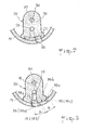
- this offset is obtained by the helical shape which has been given to the groove 22 of the dispenser, said groove covering at most only part of the holes 35 of a column, said holes being aligned on a generator 36.
- the offset is obtained by the combination of the straight shape of the groove 22 (parallel to the generatrices 36) and by the angular offset B of the alignment generators (39a, 39b, 39c) of the holes 35 of a column which, this time, are divided into three distinct groups.
- the groove 22 is in communication only with the holes 35 of only one of the three groups 38a, 38b, 38c of a column of superimposed sectors.
Priority Applications (1)
| Application Number | Priority Date | Filing Date | Title |
|---|---|---|---|
| AT84401581T ATE22815T1 (de) | 1983-08-08 | 1984-07-27 | Filter mit einer reinigungseinrichtung versehen. |
Applications Claiming Priority (2)
| Application Number | Priority Date | Filing Date | Title |
|---|---|---|---|
| FR8313043A FR2550463B1 (fr) | 1983-08-08 | 1983-08-08 | Filtre muni d'un dispositif de decolmatage |
| FR8313043 | 1983-08-08 |
Publications (2)
| Publication Number | Publication Date |
|---|---|
| EP0136202A1 true EP0136202A1 (de) | 1985-04-03 |
| EP0136202B1 EP0136202B1 (de) | 1986-10-15 |
Family
ID=9291485
Family Applications (1)
| Application Number | Title | Priority Date | Filing Date |
|---|---|---|---|
| EP84401581A Expired EP0136202B1 (de) | 1983-08-08 | 1984-07-27 | Filter mit einer Reinigungseinrichtung versehen |
Country Status (10)
| Country | Link |
|---|---|
| US (1) | US4601826A (de) |
| EP (1) | EP0136202B1 (de) |
| JP (1) | JPS60106509A (de) |
| AT (1) | ATE22815T1 (de) |
| CA (1) | CA1236031A (de) |
| DE (1) | DE3460937D1 (de) |
| ES (1) | ES289774Y (de) |
| FI (1) | FI73891C (de) |
| FR (1) | FR2550463B1 (de) |
| IN (1) | IN161498B (de) |
Cited By (4)
| Publication number | Priority date | Publication date | Assignee | Title |
|---|---|---|---|---|
| FR2725917A1 (fr) * | 1994-10-19 | 1996-04-26 | Moatti Filtration | Ensemble de traitement d'un fluide par filtration et centrifugation |
| WO1996023590A1 (en) * | 1995-02-02 | 1996-08-08 | The Glacier Metal Company Limited | Liquid cleaning system including back-flushing filter and centrifugal cleaner therefor |
| WO2000061923A1 (en) * | 1999-04-12 | 2000-10-19 | Filterwerk Mann+Hummel Gmbh | Liquid cleaning arrangement |
| US7947302B2 (en) | 2005-08-31 | 2011-05-24 | Cordis Corporation | Antithrombotic coating for drug eluting medical devices |
Families Citing this family (8)
| Publication number | Priority date | Publication date | Assignee | Title |
|---|---|---|---|---|
| DE8502177U1 (de) * | 1985-01-28 | 1985-08-08 | Kemmelmeyer, Werner H., 8201 Rohrdorf | Filtervorrichtung in Segmentbauweise |
| IL93160A (en) * | 1990-01-24 | 1992-12-01 | Rosenberg Peretz | Back-flushable filter |
| FR2964329B1 (fr) * | 2010-09-03 | 2012-09-28 | Alfa Laval Moatti | Filtre a decolmatage automatique |
| DE202014104200U1 (de) * | 2014-06-11 | 2015-09-14 | Boll & Kirch Filterbau Gmbh | Rückspülfilter und Filtereinsatz hierfür |
| DE102017002646A1 (de) * | 2017-03-18 | 2018-09-20 | Hydac Process Technology Gmbh | Filtervorrichtung |
| PL3782711T3 (pl) * | 2019-08-19 | 2022-06-20 | Alfa Laval Moatti | Jednostka filtrująca z ulepszoną pokrywą |
| KR102183820B1 (ko) * | 2020-03-10 | 2020-11-30 | 주식회사 그레넥스 | 섬유상 여과기의 역세정 흡입장치 |
| CN112554992A (zh) * | 2020-11-04 | 2021-03-26 | 李冬菊 | 一种汽车机油净化用滤清器 |
Citations (4)
| Publication number | Priority date | Publication date | Assignee | Title |
|---|---|---|---|---|
| FR2120940A5 (de) * | 1970-12-28 | 1972-08-18 | Kanagawa Kiki Kogyo Co Ltd | |
| FR2138238A1 (de) * | 1971-05-19 | 1973-01-05 | Moatti Georges | |
| FR2143694A1 (de) * | 1971-06-30 | 1973-02-09 | Kanagawa Kiki Kogyo Co Ltd | |
| FR2181510A2 (de) * | 1972-04-26 | 1973-12-07 | Moatti Georges |
Family Cites Families (6)
| Publication number | Priority date | Publication date | Assignee | Title |
|---|---|---|---|---|
| US2799397A (en) * | 1952-12-31 | 1957-07-16 | Berline Raoul | Pressure filters |
| US3985656A (en) * | 1974-04-29 | 1976-10-12 | Kostas Savas Arvanitakis | Filter cleaning apparatus |
| FI54060C (fi) * | 1976-09-14 | 1978-10-10 | Rauma Repola Oy | Skivfilter |
| FR2460398A1 (fr) * | 1979-07-02 | 1981-01-23 | Moatti Georges | Moteur hydraulique |
| US4330405A (en) * | 1980-09-29 | 1982-05-18 | Davis Kent L | Vacuum disc filter |
| DE3131281C2 (de) * | 1981-08-07 | 1993-10-21 | Fluidtech Gmbh | Vorrichtung zum getrennten Führen zweier Ströme, wahlweise nur eines Stromes, mindestens eines Mediums |
-
1983
- 1983-08-08 FR FR8313043A patent/FR2550463B1/fr not_active Expired
-
1984
- 1984-07-27 EP EP84401581A patent/EP0136202B1/de not_active Expired
- 1984-07-27 AT AT84401581T patent/ATE22815T1/de not_active IP Right Cessation
- 1984-07-27 DE DE8484401581T patent/DE3460937D1/de not_active Expired
- 1984-07-30 IN IN617/DEL/84A patent/IN161498B/en unknown
- 1984-07-30 US US06/636,100 patent/US4601826A/en not_active Expired - Lifetime
- 1984-08-03 CA CA000460366A patent/CA1236031A/en not_active Expired
- 1984-08-07 FI FI843105A patent/FI73891C/fi not_active IP Right Cessation
- 1984-08-07 ES ES1984289774U patent/ES289774Y/es not_active Expired
- 1984-08-08 JP JP59165016A patent/JPS60106509A/ja active Granted
Patent Citations (4)
| Publication number | Priority date | Publication date | Assignee | Title |
|---|---|---|---|---|
| FR2120940A5 (de) * | 1970-12-28 | 1972-08-18 | Kanagawa Kiki Kogyo Co Ltd | |
| FR2138238A1 (de) * | 1971-05-19 | 1973-01-05 | Moatti Georges | |
| FR2143694A1 (de) * | 1971-06-30 | 1973-02-09 | Kanagawa Kiki Kogyo Co Ltd | |
| FR2181510A2 (de) * | 1972-04-26 | 1973-12-07 | Moatti Georges |
Cited By (7)
| Publication number | Priority date | Publication date | Assignee | Title |
|---|---|---|---|---|
| FR2725917A1 (fr) * | 1994-10-19 | 1996-04-26 | Moatti Filtration | Ensemble de traitement d'un fluide par filtration et centrifugation |
| WO1996012549A1 (fr) * | 1994-10-19 | 1996-05-02 | Alfa Laval Moatti Snc | Ensemble de traitement d'un fluide par filtration et centrifugation |
| US5674392A (en) * | 1994-10-19 | 1997-10-07 | Moatti Filtration S.A. | Treatment assembly for treating a fluid by filtering and centrifuging |
| WO1996023590A1 (en) * | 1995-02-02 | 1996-08-08 | The Glacier Metal Company Limited | Liquid cleaning system including back-flushing filter and centrifugal cleaner therefor |
| US5906733A (en) * | 1995-02-02 | 1999-05-25 | The Glacier Metal Company Limited | Liquid cleaning system including back-flushing filter and centrifugal cleaner therefor |
| WO2000061923A1 (en) * | 1999-04-12 | 2000-10-19 | Filterwerk Mann+Hummel Gmbh | Liquid cleaning arrangement |
| US7947302B2 (en) | 2005-08-31 | 2011-05-24 | Cordis Corporation | Antithrombotic coating for drug eluting medical devices |
Also Published As
| Publication number | Publication date |
|---|---|
| FI843105A0 (fi) | 1984-08-07 |
| FI73891B (fi) | 1987-08-31 |
| FI73891C (fi) | 1987-12-10 |
| FR2550463A1 (fr) | 1985-02-15 |
| US4601826A (en) | 1986-07-22 |
| ES289774Y (es) | 1986-10-16 |
| JPS60106509A (ja) | 1985-06-12 |
| JPH0128605B2 (de) | 1989-06-05 |
| ES289774U (es) | 1986-03-01 |
| DE3460937D1 (en) | 1986-11-20 |
| FR2550463B1 (fr) | 1985-12-06 |
| CA1236031A (en) | 1988-05-03 |
| IN161498B (de) | 1987-12-12 |
| FI843105A (fi) | 1985-02-09 |
| ATE22815T1 (de) | 1986-11-15 |
| EP0136202B1 (de) | 1986-10-15 |
Similar Documents
| Publication | Publication Date | Title |
|---|---|---|
| EP0136202B1 (de) | Filter mit einer Reinigungseinrichtung versehen | |
| EP0145552A2 (de) | Filter mit zwei unterschiedlichen Filteraufbauten | |
| EP0787032B2 (de) | Vorrichtung zum behandlung von flüssigkeit mittels filtration und zentrifugation | |
| EP0062549B1 (de) | Vorrichtung zum Filtern von Fluiden und in dieser Vorrichtung durchgeführtes Verfahren | |
| EP0108665B1 (de) | Fluidumfilter | |
| CH433194A (fr) | Dispositif de filtration mécanique multicellulaire à nettoyage automatique continu pour liquides sous pression | |
| FR2857720A1 (fr) | Valve de permutation de passages d'huile contenant un filtre a huile | |
| EP0734751A1 (de) | Zyklonabscheider mit Koaleszenzelement | |
| EP2980405B1 (de) | Verteilungsvorrichtung für eine hydraulische maschine | |
| EP0284460A1 (de) | Druckflüssigkeitsmechanismus, Pumpe oder Motor mit mehreren Verdrängungsvolumen | |
| FR2677893A1 (fr) | Filtre a fluide comportant deux ensembles de filtration. | |
| EP0149931B1 (de) | Filter mit mehreren Aufnahmekammern für das Filtrat und für eine andere Flüssigkeit welche durch den Rückstand den Hauptfiltrierung gebildet ist | |
| FR2762364A1 (fr) | Injecteur de carburant pour moteur a combustion interne | |
| FR3038348B1 (fr) | Machine hydraulique a pistons radiaux a distribution en harmonique | |
| FR2624795A1 (fr) | Dispositif destine a recevoir une combinaison de deux chambres a volume variable et d'une pluralite de valves pour circuit d'alimentation d'une tete d'impression a jet d'encre | |
| FR2495240A1 (fr) | Dispositif de distribution notamment pour systeme de direction assistee d'un vehicule automobile | |
| FR2637944A1 (fr) | Mecanisme a fluide sous pression a deux cylindrees et circuit ferme en faisant application | |
| EP1466092A1 (de) | Radialkolbenhydraulikmotor | |
| EP0053559A1 (de) | Verteilungseinrichtung, insbesondere für eine Servolenkungsanlage | |
| EP0607069B1 (de) | Flüssigkeitsmotorkolben | |
| FR2797197A1 (fr) | Dispositif de maintien d'un medium filtrant pour liquide circulant dans un moteur ou un equipement hydraulique, cartouche et ensemble de filtrage correspondants | |
| FR2507681A1 (de) | ||
| FR2645913A1 (fr) | Dispositif de transfert de carburant d'un reservoir a un moteur a combustion interne, en particulier d'un vehicule automobile | |
| FR2474102A1 (fr) | Pompe d'injection de carburant | |
| FR2520445A1 (fr) | Injecteur de combustible |
Legal Events
| Date | Code | Title | Description |
|---|---|---|---|
| PUAI | Public reference made under article 153(3) epc to a published international application that has entered the european phase |
Free format text: ORIGINAL CODE: 0009012 |
|
| AK | Designated contracting states |
Designated state(s): AT BE CH DE GB IT LI NL SE |
|
| 17P | Request for examination filed |
Effective date: 19850401 |
|
| GRAA | (expected) grant |
Free format text: ORIGINAL CODE: 0009210 |
|
| AK | Designated contracting states |
Kind code of ref document: B1 Designated state(s): AT BE CH DE GB IT LI NL SE |
|
| REF | Corresponds to: |
Ref document number: 22815 Country of ref document: AT Date of ref document: 19861115 Kind code of ref document: T |
|
| ITF | It: translation for a ep patent filed |
Owner name: JACOBACCI & PERANI S.P.A. |
|
| REF | Corresponds to: |
Ref document number: 3460937 Country of ref document: DE Date of ref document: 19861120 |
|
| PLBE | No opposition filed within time limit |
Free format text: ORIGINAL CODE: 0009261 |
|
| STAA | Information on the status of an ep patent application or granted ep patent |
Free format text: STATUS: NO OPPOSITION FILED WITHIN TIME LIMIT |
|
| 26N | No opposition filed | ||
| ITTA | It: last paid annual fee | ||
| EAL | Se: european patent in force in sweden |
Ref document number: 84401581.8 |
|
| NLT1 | Nl: modifications of names registered in virtue of documents presented to the patent office pursuant to art. 16 a, paragraph 1 |
Owner name: ALFA LAVAL MOATTI SNC;MOATTI FILTRATION S.A. |
|
| REG | Reference to a national code |
Ref country code: CH Ref legal event code: PUE Owner name: GEORGES MOATTI, SOCIETE ANONYME TRANSFER- ALFA LAV |
|
| BECN | Be: change of holder's name |
Effective date: 19970121 |
|
| REG | Reference to a national code |
Ref country code: GB Ref legal event code: IF02 |
|
| PGFP | Annual fee paid to national office [announced via postgrant information from national office to epo] |
Ref country code: NL Payment date: 20020618 Year of fee payment: 19 |
|
| PGFP | Annual fee paid to national office [announced via postgrant information from national office to epo] |
Ref country code: SE Payment date: 20020619 Year of fee payment: 19 Ref country code: AT Payment date: 20020619 Year of fee payment: 19 |
|
| PGFP | Annual fee paid to national office [announced via postgrant information from national office to epo] |
Ref country code: CH Payment date: 20020711 Year of fee payment: 19 |
|
| PGFP | Annual fee paid to national office [announced via postgrant information from national office to epo] |
Ref country code: GB Payment date: 20020719 Year of fee payment: 19 |
|
| PGFP | Annual fee paid to national office [announced via postgrant information from national office to epo] |
Ref country code: BE Payment date: 20020805 Year of fee payment: 19 |
|
| PGFP | Annual fee paid to national office [announced via postgrant information from national office to epo] |
Ref country code: DE Payment date: 20030708 Year of fee payment: 20 |
|
| PG25 | Lapsed in a contracting state [announced via postgrant information from national office to epo] |
Ref country code: GB Free format text: LAPSE BECAUSE OF NON-PAYMENT OF DUE FEES Effective date: 20030727 Ref country code: AT Free format text: LAPSE BECAUSE OF NON-PAYMENT OF DUE FEES Effective date: 20030727 |
|
| PG25 | Lapsed in a contracting state [announced via postgrant information from national office to epo] |
Ref country code: SE Free format text: LAPSE BECAUSE OF NON-PAYMENT OF DUE FEES Effective date: 20030728 |
|
| PG25 | Lapsed in a contracting state [announced via postgrant information from national office to epo] |
Ref country code: LI Free format text: LAPSE BECAUSE OF NON-PAYMENT OF DUE FEES Effective date: 20030731 Ref country code: CH Free format text: LAPSE BECAUSE OF NON-PAYMENT OF DUE FEES Effective date: 20030731 Ref country code: BE Free format text: LAPSE BECAUSE OF NON-PAYMENT OF DUE FEES Effective date: 20030731 |
|
| BERE | Be: lapsed |
Owner name: *ALFA LAVAL MOATTI SNC Effective date: 20030731 |
|
| PG25 | Lapsed in a contracting state [announced via postgrant information from national office to epo] |
Ref country code: NL Free format text: LAPSE BECAUSE OF NON-PAYMENT OF DUE FEES Effective date: 20040201 |
|
| EUG | Se: european patent has lapsed | ||
| REG | Reference to a national code |
Ref country code: CH Ref legal event code: PL |
|
| GBPC | Gb: european patent ceased through non-payment of renewal fee |
Effective date: 20030727 |
|
| NLV4 | Nl: lapsed or anulled due to non-payment of the annual fee |
Effective date: 20040201 |