EP0135907B1 - Circuitry for exciting a piezoelectric oscillator in an ultrasound therapy device - Google Patents
Circuitry for exciting a piezoelectric oscillator in an ultrasound therapy device Download PDFInfo
- Publication number
- EP0135907B1 EP0135907B1 EP84111125A EP84111125A EP0135907B1 EP 0135907 B1 EP0135907 B1 EP 0135907B1 EP 84111125 A EP84111125 A EP 84111125A EP 84111125 A EP84111125 A EP 84111125A EP 0135907 B1 EP0135907 B1 EP 0135907B1
- Authority
- EP
- European Patent Office
- Prior art keywords
- oscillator
- voltage source
- terminal
- vibrator
- voltage
- Prior art date
- Legal status (The legal status is an assumption and is not a legal conclusion. Google has not performed a legal analysis and makes no representation as to the accuracy of the status listed.)
- Expired
Links
Images
Classifications
-
- B—PERFORMING OPERATIONS; TRANSPORTING
- B06—GENERATING OR TRANSMITTING MECHANICAL VIBRATIONS IN GENERAL
- B06B—METHODS OR APPARATUS FOR GENERATING OR TRANSMITTING MECHANICAL VIBRATIONS OF INFRASONIC, SONIC, OR ULTRASONIC FREQUENCY, e.g. FOR PERFORMING MECHANICAL WORK IN GENERAL
- B06B1/00—Methods or apparatus for generating mechanical vibrations of infrasonic, sonic, or ultrasonic frequency
- B06B1/02—Methods or apparatus for generating mechanical vibrations of infrasonic, sonic, or ultrasonic frequency making use of electrical energy
- B06B1/0207—Driving circuits
- B06B1/0223—Driving circuits for generating signals continuous in time
- B06B1/0238—Driving circuits for generating signals continuous in time of a single frequency, e.g. a sine-wave
- B06B1/0246—Driving circuits for generating signals continuous in time of a single frequency, e.g. a sine-wave with a feedback signal
- B06B1/0253—Driving circuits for generating signals continuous in time of a single frequency, e.g. a sine-wave with a feedback signal taken directly from the generator circuit
-
- B—PERFORMING OPERATIONS; TRANSPORTING
- B06—GENERATING OR TRANSMITTING MECHANICAL VIBRATIONS IN GENERAL
- B06B—METHODS OR APPARATUS FOR GENERATING OR TRANSMITTING MECHANICAL VIBRATIONS OF INFRASONIC, SONIC, OR ULTRASONIC FREQUENCY, e.g. FOR PERFORMING MECHANICAL WORK IN GENERAL
- B06B2201/00—Indexing scheme associated with B06B1/0207 for details covered by B06B1/0207 but not provided for in any of its subgroups
- B06B2201/50—Application to a particular transducer type
- B06B2201/55—Piezoelectric transducer
-
- B—PERFORMING OPERATIONS; TRANSPORTING
- B06—GENERATING OR TRANSMITTING MECHANICAL VIBRATIONS IN GENERAL
- B06B—METHODS OR APPARATUS FOR GENERATING OR TRANSMITTING MECHANICAL VIBRATIONS OF INFRASONIC, SONIC, OR ULTRASONIC FREQUENCY, e.g. FOR PERFORMING MECHANICAL WORK IN GENERAL
- B06B2201/00—Indexing scheme associated with B06B1/0207 for details covered by B06B1/0207 but not provided for in any of its subgroups
- B06B2201/70—Specific application
- B06B2201/76—Medical, dental
Definitions
- the invention relates to a circuit arrangement for supplying the piezoelectric oscillator in an ultrasound therapy head according to the preamble of claim 1.
- the ultrasound therapy head was connected via a power amplifier to an oscillator which oscillates at a fixed frequency.
- One was therefore forced either to keep the resonance frequency in a very narrow tolerance band when manufacturing the therapy heads or to readjust the oscillator when the therapy head was changed.
- the invention has for its object to improve a circuit arrangement of the type mentioned with a simple structure so that a much higher efficiency is achieved; this should be retained without readjusting the frequency of the oscillator even when the therapy head is changed, provided the resonance frequency of the therapy heads is within a practically acceptable tolerance range.
- the inventive solution to this problem is characterized in claim 1. It is characterized by extremely low circuit complexity and an unusually high level of efficiency. In conjunction with a very low-resistance therapy head according to DE-U-82 20 944, an efficiency of about 60% could be achieved at the high resonance frequency of 880 kHz.
- the therapy head is part of the oscillator, which cannot oscillate without the therapy head.
- the resonance frequency of the series resonance circuit is approximately matched to the middle of the tolerance band for the resonance frequency of the therapy head that can be used: As long as the resonance frequency of a therapy head is between 870 and 880 kHz, no adjustment of the resonance frequency of the series resonance circuit is necessary. Nevertheless, the oscillator vibrates at the resonance frequency of the therapy head.
- an oscillator circuit for an ultrasonic atomizer with a bipolar transistor which also works with a feedback transformer and a series resonant circuit in the control circuit of the transistor.
- the low resistance of the series resonance circuit at the resonance frequency means that the transistor works continuously in saturation, which makes it slow and it is not possible to achieve an operating frequency that is significantly above 100 kHz.
- the arrangement according to the invention of the series resonance circuit in the control circuit of a power PA field effect transistor does just the opposite: the series resonance circuit, which has a low impedance at resonance frequency, enables the capacitance of the control path of the field effect transistor to be discharged extremely quickly, so that the circuit arrangement according to the invention can oscillate at a frequency that is practically of the order of magnitude lies above the frequency for which power field effect transistors have been used up to now.
- devices which protect the field effect transistor from overvoltages, such as can occur when the ultrasound therapy head is not under load: in addition to a low-pass filter parallel to the drain source line, a protective device can be provided which is controlled by the voltage at the drain source line and switches off the oscillator when the voltage mentioned reaches a critical value.
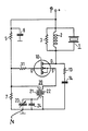
- 1 designates the piezoceramic vibrator of an ultrasound therapy head, the structure of which is described in detail in DE-U-82 20 944 and which has a real resistance of ⁇ 20 ohms at the series resonance point.
- the parallel circuit comprising this oscillator 1, an RF choke 2 and a resistor 3 is connected between the first terminal P of a DC voltage source (not shown) and the drain electrode D of a power field-effect transistor, which is connected via a low-pass filter with a resistor 13 and a capacitor 14 on the other hand, is connected to the second terminal N of the DC voltage source.
- the primary winding 22 of a feedback transformer 20 Between this second terminal N and the source electrode S is the primary winding 22 of a feedback transformer 20, the secondary winding 21 of which forms a series resonance circuit with a fixed capacitor 24 and an adjustable capacitor 23, which is connected in parallel with a resistor 7; the latter forms with a further resistor 5 a voltage divider connected between the terminals P and N, the tap of which is connected via a series resistor 11 to the gate electrode G of the field effect transistor 10 and is dimensioned such that the oscillator oscillates when a direct voltage is applied.
- a capacitor 6 is also located between P and N.
- the series resonance circuit is tuned with the aid of the capacitor 23 approximately to the middle of the tolerance band in which the resonance frequencies of the therapy heads in question must lie.
- the feedback condition remains fulfilled within this tolerance band and the oscillator oscillates to the series resonance of the connected therapy head.
- the power that can be output by the therapy head can be adjusted by changing the voltage of the DC voltage source and is, for example, at
Abstract
Description
Die Erfindung betrifft eine Schaltungsanordnung zur Speisung des piezoelektrischen Schwingers in einem Ultraschall-Therapiekopf gemäss Oberbegriff des Anspruchs 1.The invention relates to a circuit arrangement for supplying the piezoelectric oscillator in an ultrasound therapy head according to the preamble of claim 1.
Bei bekannten Schaltungsanordungen dieser Art wurde der Ultraschall-Therapiekopf über einen Leistungsverstärker an einen Oszillator angeschlossen, der auf einer fest eingestellten Frequenz schwingt. Man war daher gezwungen, entweder bei der Fertigung der Therapieköpfe deren Resonanzfrequenz in einem sehr engen Toleranzband zu halten oder den Oszillator bei einem Wechsel des Therapiekopfes neu einzustellen.In known circuit arrangements of this type, the ultrasound therapy head was connected via a power amplifier to an oscillator which oscillates at a fixed frequency. One was therefore forced either to keep the resonance frequency in a very narrow tolerance band when manufacturing the therapy heads or to readjust the oscillator when the therapy head was changed.
Bei der bekannten Schaltungsanordnung liegt ferner ihr Innenwiderstand über dem minimalen Widerstand des Therapiekopfes bei dessen Serienresonanz. Um eine befriedigende Leistungsauskopplung zu erreichen, musste daher mit einer zwischen Serienresonanz und Parallelresonanz des Therapiekopfes liegenden Frequenz gearbeitet werden, bei der der Innenwiderstand der Schaltungsanordnung etwa gleich dem Betrag der Impedanz des Therapiekopfes ist; in diesem Arbeitspunkt ist aber zwangsläufig der Wirkungsgrad wesentlich schlechter als im Resonanzpunkt.In the known circuit arrangement, its internal resistance is also above the minimum resistance of the therapy head during its series resonance. In order to achieve a satisfactory output decoupling, it was therefore necessary to work with a frequency lying between series resonance and parallel resonance of the therapy head, at which the internal resistance of the circuit arrangement is approximately equal to the amount of the impedance of the therapy head; in this working point the efficiency is inevitably much worse than in the resonance point.
Der Erfindung liegt die Aufgabe zugrunde, eine Schaltungsanordnung der eingangs genannten Art bei einfacherem Aufbau so zu verbessern, dass ein wesentlich höherer Wirkungsgrad erzielt wird; dieser soll ohne Nachstellung der Frequenz des Ozillators auch bei einem Wechsel des Therapiekopfes erhalten bleiben, sofern die Resonanzfrequenz der Therapieköpfe in einem praktisch akzeptablen Toleranzbereich liegt.The invention has for its object to improve a circuit arrangement of the type mentioned with a simple structure so that a much higher efficiency is achieved; this should be retained without readjusting the frequency of the oscillator even when the therapy head is changed, provided the resonance frequency of the therapy heads is within a practically acceptable tolerance range.
Die erfindungsgemässe Lösung dieser Aufgabe ist in Anspruch 1 gekennzeichnet. Sie zeichnet sich durch äusserst niedrigen schaltungstechnischen Aufwand und einen ungewöhnlich hohen Wirkungsgrad aus. In Verbindung mit einem sehr niederohmigen Therapiekopf gemäss DE-U-82 20 944 liess sich bei der hohen Resonanzfrequenz von 880 kHz ein Wirkungsgrad von etwa 60% erzielen.The inventive solution to this problem is characterized in claim 1. It is characterized by extremely low circuit complexity and an unusually high level of efficiency. In conjunction with a very low-resistance therapy head according to DE-U-82 20 944, an efficiency of about 60% could be achieved at the high resonance frequency of 880 kHz.
Bei der Erfindung ist der Therapiekopf Teil des Oszillators, der ohne Therapiekopf nicht schwingen kann. Die Resonanzfrequenz des Serienresonanzkreises ist etwa auf die Mitte des Toleranzbandes für die Resonanzfrequenz des verwendbaren Therapiekopfes abgestimmt: Solange die Resonanzfrequenz eines Therapiekopfes etwa zwischen 870 und 880 kHz liegt, ist keine Nachstellung der Resonanzfrequenz des Serienresonanzkreises erforderlich. Trotzdem schwingt der Oszillator auf der Resonanzfrequenz des Therapiekopfes.In the invention, the therapy head is part of the oscillator, which cannot oscillate without the therapy head. The resonance frequency of the series resonance circuit is approximately matched to the middle of the tolerance band for the resonance frequency of the therapy head that can be used: As long as the resonance frequency of a therapy head is between 870 and 880 kHz, no adjustment of the resonance frequency of the series resonance circuit is necessary. Nevertheless, the oscillator vibrates at the resonance frequency of the therapy head.
Aus Elektronik, 1979, Heft 10, S. 83-90 ist zwar eine Oszillatorschaltung für einen Ultraschallzerstäuber mit einem bipolaren Transistor bekannt, der ebenfalls mit einem Rückkopplungstransformator und einem Serienresonanzkreis im Steuerkreis des Transistors arbeitet. Der niedrige Widerstand des Serienresonanzkreises bei Resonanzfrequenz führt aber hier dazu, dass der Transistor ständig in der Sättigung arbeitet, wodurch er langsam wird und keine Betriebsfrequenz erzielbar ist, die wesentlich über 100 kHz liegt. Die erfindungsgemässe Anordnung des Serienresonanzkreises im Steuerkreis eines Leistungs-PA-Feldeffekttransistors bewirkt gerade das Gegenteil: Der bei Resonanzfrequenz niederohmige Serienresonanzkreis ermöglicht eine extrem schnelle Entladung der Kapazität der Steuerstrecke des Feldeffekttransistors, so dass die erfindungsgemässe Schaltungsanordnung auf einer Frequenz schwingen kann, die praktisch eine Grössenordnung über der Frequenz liegt, für die Leistungs-Feldeffekttransistoren bisher eingesetzt wurden.From Electronics, 1979, Issue 10, pp. 83-90 an oscillator circuit for an ultrasonic atomizer with a bipolar transistor is known, which also works with a feedback transformer and a series resonant circuit in the control circuit of the transistor. However, the low resistance of the series resonance circuit at the resonance frequency means that the transistor works continuously in saturation, which makes it slow and it is not possible to achieve an operating frequency that is significantly above 100 kHz. The arrangement according to the invention of the series resonance circuit in the control circuit of a power PA field effect transistor does just the opposite: the series resonance circuit, which has a low impedance at resonance frequency, enables the capacitance of the control path of the field effect transistor to be discharged extremely quickly, so that the circuit arrangement according to the invention can oscillate at a frequency that is practically of the order of magnitude lies above the frequency for which power field effect transistors have been used up to now.
Gemäss Weiterbildungen der Erfindung sind Einrichtungen vorgesehen, die den Feldeffekttransistor vor Überspannungen schützen, wie sie bei nicht belastetem Ultraschall-Therapiekopf auftreten können: Neben einem Tiefpassfilter parallel zur Drain-Sourcestrecke kann eine Schutzeinrichtung vorgesehen sein, die mit der Spannung an der Drain-Sourcestrecke gesteuert wird und den Oszillator abschaltet, wenn die erwähnte Spannung einen kritischen Wert erreicht.According to further developments of the invention, devices are provided which protect the field effect transistor from overvoltages, such as can occur when the ultrasound therapy head is not under load: in addition to a low-pass filter parallel to the drain source line, a protective device can be provided which is controlled by the voltage at the drain source line and switches off the oscillator when the voltage mentioned reaches a critical value.
Die Erfindung wird anhand des in der Figur dargestellten Ausführungsbeispieles näher erläutert. Mit 1 ist der piezokeramische Schwinger eines Ultraschall-Therapiekopfes bezeichnet, dessen Aufbau in dem DE-U-82 20 944 im Detail beschrieben ist und der im Serienresonanzpunkt einen reellen Widerstand von < 20 Ohm hat. Die Parallelschaltung aus diesem Schwinger 1, einer HF-Drossel 2 und einem Widerstand 3 ist zwischen der ersten Klemme P einer nicht dargestellten Gleichspannungsquelle und der Drain-Elektrode D eines Leistungs-Feldeffekttransistors angeschlossen, die über ein Tiefpassfilter mit einem Widerstand 13 und einem Kondensator 14 andererseits mit der zweiten Klemme N der Gleichspannungsquelle verbunden ist. Zwischen dieser zweiten Klemme N und der Source-Elektrode S liegt die Primärwicklung 22 eines Rückkopplungstransformators 20, dessen Sekundärwicklung 21 mit einem Festkondensator 24 und einem einstellbaren Kondensator 23 einen Serienresonanzkreis bildet, der parallel zu einem Widerstand 7 liegt; letzterer bildet mit einem weiteren Widerstand 5 einen zwischen den Klemmen P und N angeschlossenen Spannungsteiler, dessen Abgriff über einen Vorwiderstand 11 mit der Gate-Elektrode G des Feldeffekttransistors 10 verbunden und so bemessen ist, dass der Oszillator bei angelegter Gleichspannung anschwingt. Zwischen P und N liegt ferner ein Kondensator 6.The invention is explained in more detail with reference to the embodiment shown in the figure. 1 designates the piezoceramic vibrator of an ultrasound therapy head, the structure of which is described in detail in DE-U-82 20 944 and which has a real resistance of <20 ohms at the series resonance point. The parallel circuit comprising this oscillator 1, an RF choke 2 and a
Der Serienresonanzkreis ist mit Hilfe des Kondensators 23 etwa auf die Mitte des Toleranzbandes abgestimmt, in dem die Resonanzfrequenzen der in Betracht kommenden Therapieköpfe liegen müssen. Innerhalb dieses Toleranzbandes bleibt die Rückkopplungsbedingung erfüllt und der Oszillator schwingt auf der Serienresonanz des angeschlossenen Therapiekopfes, Die vom Therapiekopf abgebbare Leistung lässt sich durch Verändern der Spannung der Gleichspannungsquelle einstellen und beträgt beispielsweise bei einerThe series resonance circuit is tuned with the aid of the
Spannung von 20 Volt maximal 12 Watt; dabei wurde ein Wirkungsgrad von 60% gemessen.Voltage of 20 volts maximum 12 watts; an efficiency of 60% was measured.
Claims (4)
Priority Applications (1)
| Application Number | Priority Date | Filing Date | Title |
|---|---|---|---|
| AT84111125T ATE31257T1 (en) | 1983-09-28 | 1984-09-18 | CIRCUIT FOR EXCITATION OF AN ULTRASOUND THERAPY HEAD. |
Applications Claiming Priority (2)
| Application Number | Priority Date | Filing Date | Title |
|---|---|---|---|
| DE3335158 | 1983-09-28 | ||
| DE19833335158 DE3335158A1 (en) | 1983-09-28 | 1983-09-28 | CIRCUIT FOR EXCITING AN ULTRASONIC THERAPY HEAD |
Publications (3)
| Publication Number | Publication Date |
|---|---|
| EP0135907A2 EP0135907A2 (en) | 1985-04-03 |
| EP0135907A3 EP0135907A3 (en) | 1985-06-05 |
| EP0135907B1 true EP0135907B1 (en) | 1987-12-09 |
Family
ID=6210318
Family Applications (1)
| Application Number | Title | Priority Date | Filing Date |
|---|---|---|---|
| EP84111125A Expired EP0135907B1 (en) | 1983-09-28 | 1984-09-18 | Circuitry for exciting a piezoelectric oscillator in an ultrasound therapy device |
Country Status (3)
| Country | Link |
|---|---|
| EP (1) | EP0135907B1 (en) |
| AT (1) | ATE31257T1 (en) |
| DE (2) | DE3335158A1 (en) |
Families Citing this family (3)
| Publication number | Priority date | Publication date | Assignee | Title |
|---|---|---|---|---|
| US5001649A (en) * | 1987-04-06 | 1991-03-19 | Alcon Laboratories, Inc. | Linear power control for ultrasonic probe with tuned reactance |
| DE3934921C1 (en) * | 1989-10-20 | 1991-04-25 | Kln Ultraschall Gmbh, 6148 Heppenheim, De | Switching circuitry for reactive loads such as coils, and oscillators - has diode in antiparallel with each diode in series with semiconductor switch |
| JP4889832B2 (en) * | 2010-04-09 | 2012-03-07 | オリンパスメディカルシステムズ株式会社 | Ultrasonic surgical system and surgical treatment instrument |
Family Cites Families (3)
| Publication number | Priority date | Publication date | Assignee | Title |
|---|---|---|---|---|
| US3584244A (en) * | 1969-06-10 | 1971-06-08 | Clevite Corp | Oscillator circuit for an ultrasonic cleaner, utilizing a saturable core transformer |
| US4012647A (en) * | 1974-01-31 | 1977-03-15 | Ultrasonic Systems, Inc. | Ultrasonic motors and converters |
| US4311922A (en) * | 1979-11-14 | 1982-01-19 | General Electric Company | Variable excitation circuit |
-
1983
- 1983-09-28 DE DE19833335158 patent/DE3335158A1/en not_active Withdrawn
-
1984
- 1984-09-18 DE DE8484111125T patent/DE3467981D1/en not_active Expired
- 1984-09-18 EP EP84111125A patent/EP0135907B1/en not_active Expired
- 1984-09-18 AT AT84111125T patent/ATE31257T1/en not_active IP Right Cessation
Also Published As
| Publication number | Publication date |
|---|---|
| EP0135907A2 (en) | 1985-04-03 |
| EP0135907A3 (en) | 1985-06-05 |
| ATE31257T1 (en) | 1987-12-15 |
| DE3335158A1 (en) | 1985-04-04 |
| DE3467981D1 (en) | 1988-01-21 |
Similar Documents
| Publication | Publication Date | Title |
|---|---|---|
| DE3117009C2 (en) | ||
| DE3531576C2 (en) | Electrosurgery generator | |
| DE102005055160B4 (en) | Control circuit for current and voltage control in a switching power supply | |
| DE3331896C2 (en) | ||
| EP0329988B1 (en) | High frequency power generator | |
| DE2140832A1 (en) | METHOD AND DEVICE FOR ELECTRIC HIGH FREQUENCY SURGERY | |
| DE10306347A1 (en) | Controlling supply of power from AC supply to two consumers in plasma process, by adjusting supplied power if actual power deviates from set value | |
| DE2126469A1 (en) | High-frequency line amplifier with high efficiency | |
| DE887558C (en) | Relaxation oscillator | |
| DE2932828A1 (en) | EXCITER CIRCUIT FOR AN ULTRASONIC ATOMIZER | |
| DE2916540A1 (en) | ELECTRICAL CIRCUIT ARRANGEMENT FOR CONTROLLING A PIEZOELECTRIC CONVERTER | |
| DE4208911B4 (en) | power supply | |
| EP0135907B1 (en) | Circuitry for exciting a piezoelectric oscillator in an ultrasound therapy device | |
| DE4036618C3 (en) | Device for driving a piezoelectric vibrator | |
| EP0123085A2 (en) | Electronically switched power supply with transformer choke | |
| EP0416696B1 (en) | X-ray apparatus | |
| DE10252146B4 (en) | Method for generating a high-frequency alternating voltage and high-frequency power amplifier therefor | |
| DE1275195B (en) | Generator for generating ultrasonic vibrations | |
| EP0590191B1 (en) | Circuit for frequency conversion | |
| EP2506789A2 (en) | High frequency surgery generator | |
| EP0339313A1 (en) | Stimulation apparatus | |
| CH649877A5 (en) | DEVICE WITH A LOW-FREQUENCY AMPLIFIER. | |
| EP4066765A1 (en) | Active electrosurgical instrument | |
| DE2535807A1 (en) | Ultrasonic oscillator circuit for liquid spray - has coupling transformer between pulse circuit and piezoelectric oscillator | |
| DE1246820B (en) | Transistor amplifier with a driver transistor and a push-pull output stage |
Legal Events
| Date | Code | Title | Description |
|---|---|---|---|
| PUAI | Public reference made under article 153(3) epc to a published international application that has entered the european phase |
Free format text: ORIGINAL CODE: 0009012 |
|
| AK | Designated contracting states |
Designated state(s): AT CH DE LI NL |
|
| PUAL | Search report despatched |
Free format text: ORIGINAL CODE: 0009013 |
|
| AK | Designated contracting states |
Designated state(s): AT CH DE LI NL |
|
| RTI1 | Title (correction) | ||
| 17P | Request for examination filed |
Effective date: 19851128 |
|
| 17Q | First examination report despatched |
Effective date: 19870109 |
|
| GRAA | (expected) grant |
Free format text: ORIGINAL CODE: 0009210 |
|
| AK | Designated contracting states |
Kind code of ref document: B1 Designated state(s): AT CH DE LI NL |
|
| REF | Corresponds to: |
Ref document number: 31257 Country of ref document: AT Date of ref document: 19871215 Kind code of ref document: T |
|
| REF | Corresponds to: |
Ref document number: 3467981 Country of ref document: DE Date of ref document: 19880121 |
|
| PG25 | Lapsed in a contracting state [announced via postgrant information from national office to epo] |
Ref country code: AT Effective date: 19880918 |
|
| PG25 | Lapsed in a contracting state [announced via postgrant information from national office to epo] |
Ref country code: LI Effective date: 19880930 Ref country code: CH Effective date: 19880930 |
|
| PLBE | No opposition filed within time limit |
Free format text: ORIGINAL CODE: 0009261 |
|
| STAA | Information on the status of an ep patent application or granted ep patent |
Free format text: STATUS: NO OPPOSITION FILED WITHIN TIME LIMIT |
|
| 26N | No opposition filed | ||
| PG25 | Lapsed in a contracting state [announced via postgrant information from national office to epo] |
Ref country code: NL Effective date: 19890401 |
|
| NLV4 | Nl: lapsed or anulled due to non-payment of the annual fee | ||
| REG | Reference to a national code |
Ref country code: CH Ref legal event code: PL |
|
| PG25 | Lapsed in a contracting state [announced via postgrant information from national office to epo] |
Ref country code: DE Effective date: 19890601 |