EP0135682B1 - Method and apparatus for applying emulsion onto screen printing plate - Google Patents
Method and apparatus for applying emulsion onto screen printing plate Download PDFInfo
- Publication number
- EP0135682B1 EP0135682B1 EP84107359A EP84107359A EP0135682B1 EP 0135682 B1 EP0135682 B1 EP 0135682B1 EP 84107359 A EP84107359 A EP 84107359A EP 84107359 A EP84107359 A EP 84107359A EP 0135682 B1 EP0135682 B1 EP 0135682B1
- Authority
- EP
- European Patent Office
- Prior art keywords
- screen
- squeegee
- applying
- emulsion
- squeegees
- Prior art date
- Legal status (The legal status is an assumption and is not a legal conclusion. Google has not performed a legal analysis and makes no representation as to the accuracy of the status listed.)
- Expired - Lifetime
Links
Images


Classifications
-
- G—PHYSICS
- G03—PHOTOGRAPHY; CINEMATOGRAPHY; ANALOGOUS TECHNIQUES USING WAVES OTHER THAN OPTICAL WAVES; ELECTROGRAPHY; HOLOGRAPHY
- G03F—PHOTOMECHANICAL PRODUCTION OF TEXTURED OR PATTERNED SURFACES, e.g. FOR PRINTING, FOR PROCESSING OF SEMICONDUCTOR DEVICES; MATERIALS THEREFOR; ORIGINALS THEREFOR; APPARATUS SPECIALLY ADAPTED THEREFOR
- G03F7/00—Photomechanical, e.g. photolithographic, production of textured or patterned surfaces, e.g. printing surfaces; Materials therefor, e.g. comprising photoresists; Apparatus specially adapted therefor
- G03F7/12—Production of screen printing forms or similar printing forms, e.g. stencils
-
- G—PHYSICS
- G03—PHOTOGRAPHY; CINEMATOGRAPHY; ANALOGOUS TECHNIQUES USING WAVES OTHER THAN OPTICAL WAVES; ELECTROGRAPHY; HOLOGRAPHY
- G03F—PHOTOMECHANICAL PRODUCTION OF TEXTURED OR PATTERNED SURFACES, e.g. FOR PRINTING, FOR PROCESSING OF SEMICONDUCTOR DEVICES; MATERIALS THEREFOR; ORIGINALS THEREFOR; APPARATUS SPECIALLY ADAPTED THEREFOR
- G03F7/00—Photomechanical, e.g. photolithographic, production of textured or patterned surfaces, e.g. printing surfaces; Materials therefor, e.g. comprising photoresists; Apparatus specially adapted therefor
- G03F7/16—Coating processes; Apparatus therefor
-
- Y—GENERAL TAGGING OF NEW TECHNOLOGICAL DEVELOPMENTS; GENERAL TAGGING OF CROSS-SECTIONAL TECHNOLOGIES SPANNING OVER SEVERAL SECTIONS OF THE IPC; TECHNICAL SUBJECTS COVERED BY FORMER USPC CROSS-REFERENCE ART COLLECTIONS [XRACs] AND DIGESTS
- Y10—TECHNICAL SUBJECTS COVERED BY FORMER USPC
- Y10S—TECHNICAL SUBJECTS COVERED BY FORMER USPC CROSS-REFERENCE ART COLLECTIONS [XRACs] AND DIGESTS
- Y10S430/00—Radiation imagery chemistry: process, composition, or product thereof
- Y10S430/136—Coating process making radiation sensitive element
Definitions
- This invention relates to a method and an apparatus for applying an emulsion onto a screen printing plate in which, upon applying the emulsion of a photo-sensitive material onto the plate screen to be used for the screen printing process, the whole face of the screen may be applied with a film of uniform thickness with its ink-applying side being thin while its printing side being thick.
- the emulsion has been applied by vertically slidable squeegees of a bucket type having contacted at their front edges with the screen consisting of a screen material of silk, polyester, nylon or the like of a given mesh size and a frame surrounding the screen material.
- manual moving operation requires a particularly high skill for applying a film of a uniform thickness.
- various types of mechanically moving squeegees as disclosed in U.S. Patent 4363289 (corres. to the Published European Patent Application 0026538).
- the U.S. Patent relates to a method and an apparatus for applying an emulsion onto a screen printing, in which squeegees arranged at either side of the screen are advanced toward the screen face for contacting therewith, inclined for flowing the emulsion out of the squeegees at their front edges, and vertically moved relative to the screen.
- the emulsion flows down naturally from, the squeegees, so that the emulsion may be scraped by the front edge of the squeegee upon its upward movement for providing a uniform film thickness, whereas upon its downward movement (necessary for thick application) the emulsion may flow into the underside of the squeegee and is applied in different quantities thereby to provide a much irregular thickness.
- a certain distance between the screen face and the front edges of the squeegees is needed for giving a relatively thick emulsion film, because the contacted squeegees may scrape off the applied emulsion.
- the screen with a larger thickness of the emulsion on its printing side can not be produced.
- the squeegees on both sides of the screen are symmetrically moved synchronously with each other by a single cylinder, so that one of the squeegees must be replaced by a rod or roller for application only on a single side of the screen, requiring a troublesome replacement and resulting in a very difficult switch over of the application from both sides to the single side of the screen or vice versa through continuous and automatic operation.
- application of the more thick emulsion on the printing side than on the ink-applying side is essential for obtaining a beautiful print, which is difficult to be achieved by the prior art as described hereinabove.
- an object of the invention is to solve the above problems of the prior art and to provide a method and an apparatus for applying a more uniform thickness of an emulsion over the entire surface of a screen with its ink-applying side being thin while its printing side being thick for producing a beautiful print, in which one of squeegees arranged on one side of the screen is used for applying the emulsion while the other is used for scraping and recovering the emulsion, in which each of the squeegees is movable independently and only the applying squeegee may be inclined, and in which the emulsion is applied only during upward movement of the applying squeegee while the uniform application of the emulsion through the screen mesh and its recovery may be effected.
- the above object may be achieved by the method for applying an emulsion onto a vertically oriented screen printing plate by operating vertically and independently movable squeegees arranged on either side of the screen comprising the successive steps as defined in claim 1.
- an apparatus for embodying the method as described hereinabove which comprises a base consisted of a frame having walls at its opposite sides; a supporting mechanism having clamps for supporting the screen vertically; a lifting mechanism for lifting along the screen an applying squeegee and a scraping squeegee arranged on both sides of the screen; actuating mechanisms for the squeegees, one of said actuating mechanisms allowing the applying squeegee to move toward the screen, to be contacted at its leading edge with the screen and to be inclined upon its upward movement while the other actuating mechanism allowing the scraping squeegee to be not contacted with the screen, or to move toward the screen and to be contacted at its leading edge with the screen but not to be inclined upon its upward movement, both of said squeegees being restored to their horizontal state and retreated to be spaced apart from the screen upon their downward movement; and a controlling mechanism for controlling the movement of each squeegee
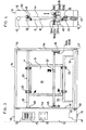
- a frame 10 comprises a base 11 positioned horizontally by an adjuster 15, upright side walls 12, 13 arranged oppositely on the base 11, and an upper wall 14 between the side walls 12 and 13.
- the left wall 12 at its front is provided with an operational panel 72, 73 for previously setting various inputs of a controlling mechanism 70 and at its lower part is provided with a motor 41 as a driving source of a mechanism 40 for vertically moving squeegees.
- a screen printing plate S which consists essentially of a screen material M made of silk, polyester, nylon or the like of a given mesh size and a frame P surrounding the screen material S. Further, a supporting mechanism 20, a mechanism 40 and a squeegee actuating mechanism 50A, 50B are incorporated therein for applying an emulsion D of a liquid photo-sensitive material onto the screen S.
- the supporting mechanism 20 comprises bars 21, 22, for fixing clamp 23 supporting the screen S, which bars are arranged horizontally between the side walls 12, 13 and between upright stands on the base 11.
- the upper bar 21 is slidably adjustable for its vertical position and applicable to different sizes of the screen S.
- a suitable plurality of the clamps 23 fixed to the bars 21, 22 may be of any gripping type, such as a cylinder operation type, a screw fixing type and others, for gripping the frame P of the screen S so as to allow rapid and reliable attachment and removal of the screen S.
- the emulsion D is applied onto the screen material M by the mechanisms 40, 50A and 50B through sequential steps including a first step for applying the emulsion D Qnto one side of the screen S, a second step for applying the emulsion D onto said one side while scraping off and recovering the emulsion D on the other side of the screen S and a third step for applying the emulsion repeatedly by urging the latter through the screen S from its ink-applying side to its printing side.
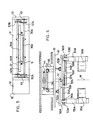
- the mechanism 40 has a function to vertically move the applying and the scraping squeegees 35A, 35B of a bucket type along the screen face and practically comprises supporting bars 55A, 55B for releasably mounting the applying and the scraping squeegees 35A and 35B, units 45 arranged oppositely on the inner sides of the side, walls 12, 13 for mounting the supporting bars 55A, 55B therebetween, chains 44 driven within the side walls 12, 13 and cooperated with the units 45, guides 42 arranged in the side walls 12, 13 and guide rollers 47 running along the guides 42.
- each guide 42 at its upper and lower parts is provided with sprocket wheels 43, the chain 44 over which is driven by the motor 41 accommodated in the lower part of the left wall 12, thereby to vertically move the units 45. Since the moving extent of the units 45 may be limited to a distance between the upper and the lower ends of the screen S secured to the supporting mechanism 20, the corresponding upper and lower positions on the side walls 12, 13 are provided with an upper and a lower limit switches 48 for discontinuing the motor 41 upon contact with the unit 45.
- the unit 45 and the chain 44 are associated by securing an engaging portion 46 protruded behind the unit 45 to the chain 44 behind the guide 42.
- the engaging portion 46 supports the guide rollers 47 contacted with a leading and a trailing edges of the guide 42. These guide rollers 47 move along the guide 42 thereby to allow smooth vertical movement of the unit 45 in association with the driven chain 44 and to ensure a constant pressure of the squeegees 35A, 35B against the screen face and a constant distance therebetween.
- a buffering material may be inserted between the guide 42 and the guide rollers 47 for absorbing shock and vibration during movement.
- the squeegee operational mechanisms 50A, 50B allow the squeegee 35A to be moved toward the screen face M, for contacting its front edge therewith and to be inclined upon upward movement of the applying squeegee 35A, while they allow the squeegee 35B to be kept uncontacted with the screen face M, or to be moved toward the screen face M for contacting its front edge therewith but not to be inclined upon upward movement of the squeegee 35B. Further, upon downward movement of the squeegees 35A, 35B the mechanisms 50A, 50B allow both squeegees to be restored to their horizontal position and retreated apart from the screen face M.
- the squeegees 35A, 35B arranged on either side of the screen S may be operated individually.
- the squeegees 35A, 35B according to the invention may be operated simultaneously with one squeegee being served as the applying squeegee for applying the emulsion D onto one side of the screen, while the other squeegee being served for scraping and recovering the emulsion D from the other side of the screen.
- the applying squeegee 35A (or 35B) is moved toward the screen and inclined, while the scraping squeegee 35B (or 35A) is also moved toward the screen but not inclined.
- each squeegee 35A, 35B may eliminate requirement for setting or selecting the specific side of the screen upon setting by means of the supporting mechanism 20, thereby to improve the operability of the apparatus according to the invention.
- either one of the squeegees 35A, 35B may be utilized as the applying or the scraping squeegee.
- the squeegee operational mechanisms 50A, 50B are arranged symmetrically and their individual movement may be controlled by a controlling mechanism 70, as described hereinafter.
- the squeegee operational mechanisms 50A, 50B comprise, as shown in Fig. 6, a pair of units 45 vertically movable along the side walls 12, 13, a pair of inclining arms 52A, 52B swingably supported to the units, a pair of supporting bars 55A, 55B arranged between the arms 52A and 52B to be slidably guided along slide shafts 54A, 54B, cylinders 57A, 57B secured to the arms 52A, 52B and having pistons 58A, 58B connected to the supporting bars 55A, 55B, and cylinders 60A, 60B secured to the units 45 and having pistons 61A, 60B connected to the arms 52A, 52B.
- the cylinders 57A, 57B may be used for the horizontal reciprocating movement, while the cylinders 60A, 60B for the inclining movement.
- the squeegees 35A, 35B mounted to the supporting bars 55A, 55B apply the emulsion D, they advance toward the screen M to make their front edges contacted therewith and then are inclined to pour the emulsion D (or the photosensitive liquid material) out of the squeegees onto the screen for penetration into its mesh.
- the squeegees 35A, 35B are desirably swung on their front edges in order to achieve inclination.
- the supporting bars 55A, 55B are provided between the inclining arms 52A and 528.
- the inclining movement of the arms 52A, 52B with time difference ensures the inclined attitude of the squeegees 35A, 35B for positioning their front edges on the same line as the supporting position of the arms 52A, 52B.
- the squeegee actuating mechanisms 50A and 50B which actuate the squeegees 35A, 35B relative to the screen M supported by the supporting mechanism 20, are arranged symmetrically, while the supporting position of the arms 52A, 52B is located on a portion of the unit 45 which is situated on an extention from the screen material M, as best shown in Fig. 6.
- the urging force may be imparted upon the upward movement to prevent the screen from being damaged and the adequate tension may be imparted to ensure an excellent application of the emulsion D.
- the screen face may be undulated due to the urging force by the squeegees, thereby to ensure the smooth application of the emulsion D onto the screen.
- the undulation of the screen face due to the urging force by the squeegees may eliminate the ununiformity of the tension or may impart a constant tension to the screen.
- a constant thickness of applied film may be achieved irrespective of a degree of tension when the screen is initially arranged.
- the arms 52A, 52B are provided with a pair of supports 53A, 53B, between which are horizontally arranged slide shafts 54A, 54B as well as cylinders 57A, 57B for horizontal movement which have their pistons 58A, 58B extended in parallel to the slide shaft 54A, 54B and connected at their front ends to joints 59A, 59B protruded from the supporting bars 55A, 55B.
- cylinders 60A, 60B for inclining movement are arranged vertically below the inclining arms 52A, 52B and secured to the unit base 45, pistons 61A, 61B of which at their front ends are connected to the arms 52A, 52B.
- the supporting bars 55A, 55B are provided at their either ends with ball bushings 56A, 56B which are fitted to the slide shafts 54A, 54B. Due to arrangement of the ball bushings 56A, 56B the supporting bars 55A, 55B may move smoothly along the slide shafts 54A, 54B with low friction, thereby preventing the long supporting bars 55A, 55B from being deviated and thus stabilizing the movement.
- the cylinder 60A (or 60B) is operated to swing and incline the arm 52A (or 52B) and hence the squeegee 35A (or 35B), thereby to pour the emulsion D out of the squeegee onto the screen face (Fig. 9).
- the cylinder 60A (or 60B) for the inclining movement is operated to restore the inclining arm 52A (or 52B) to its horizontal state and then the cylinder 57A (or 57B) for the horizontal movement is operated to retreat the supporting bar 55A (or 55B) and hence the squeegee 35A (35B) from the screen face.
- the cylinders 57A, 57B may be operated simultaneously, while the cylinder 60A or 60B should be operated singly.
- the urging force of the squeegee 35A, 35B against the screen may be provided by the operation of the cylinder 57A, 57B and therefore may be readily adjusted by varying its air pressure. Further, the cylinder 57A, 57B is secured to the arm 52A, 52B and arranged horizontally, thereby to enable the urging force to be adjusted conveniently by the position adjustment through a forcible external force.
- the inclining arm 52A, 52B is fixed to the unit 45 by the pin 51, so that the center for the inclining movement may be kept at the constant position, thereby to allow the smooth inclination of the squeegee 35A, 35B and to allow a pressure of applying the emulsion from the squeegee to be adjusted irrespective of the position of each inclined squeege 35A, 35B.
- the squeegee 35A, 35B is formed in a bucket type which has, in its cross-section, an inclined front wall, a central round bottom and a vertical rear wall. From an upper end of the rear wall is extended perpendicularly a removable base 36A, 36B which is placed on the supporting bar 55A, 55B of a square cross-section and fixed thereto by a suitable means 37 such as a screw.
- a suitable means 37 such as a screw.
- One of the squeegees 35A, 35B arranged on both sides of the screen may be shorter than the other, in order to achieve the different levels of the front edges of the squeegees. In general, the applying squeegee is longer, wider and smaller than the recovering squeegee.
- the squeegee at its front edge may be fabricated smoothly or may be provided with a suitable elastic material in order to prevent the contacted screen face from being damaged.
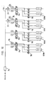
- the apparatus is provided with the controlling mechanism which comprises an electric, hydraulic or pneumatic circuit and controls the vertical movement of the squeegees 35A, 35B through the mechanism 40 as well as the horizontal and the inclining movement of the squeegees.
- the controlling mechanism which comprises an electric, hydraulic or pneumatic circuit and controls the vertical movement of the squeegees 35A, 35B through the mechanism 40 as well as the horizontal and the inclining movement of the squeegees.
- four cylinders 57A, 57B for the horizontal movement and four cylinders 60A, 60B for the inclining movement in the squeegee actuating mechanism 50A, 50B may be supplied with an operating air or exhausted. These cylinders may be separately and independently operated by separate lines.
- An evacuating unit 74, a valve 75, a muffler 76, a reducing valve 77 and a speed controller 78 may be controlled, as shown in Fig.
- the screen printing S is secured to the crank fixing bars 21, 22 of the supporting mechanism 20 by means of the clamp 23.
- the applying squeegee 35A mounted to the supporting bar 55A is filled with the emulsion D and the applying number of times for the third step is set by various setting buttons on the operation panels 72, 73.
- the starting switch 71 is energized to start the operation.
- the cylinder 57A for the horizontal movement in the squeegee actuating mechanism 50A is operated to advance the supporting bar 55A and hence the squeegee 35A toward the screen face, thereby to allow its front edge to be contacted with the screen face.
- the cylinder 60A for the inclining movement is operated to swing and incline the inclining arm 52A for lifting the rear end of the squeegee 35A, thereby pouring the emulsion D out of the squeegee 35A onto the screen.
- a variable timer may be provided for suitably setting a time for the emulsion D to become compatible to the screen.
- the squeegee moving mechanism 40 is operated to move the unit 45 upward through the endless chain 44, thereby to lift the supporting bar 55A, and the squeegee 35A for applying the emulsion D from the squeegee 35A onto the screen.
- the other squeegee 35B is not working and spaced apart from the screen face. If the squeegee 35A reaches the predetermined upper position for finishing the application of the emulsion D, then it discontinues its upward movement and thereafter the cylinder 60A is reoperated to restore the horizontal state of the squeegee 35A or, if necessary, it continues its upward movement with the horizontal state for scraping and recovering the emulsion D flooded out of the squeegee 35A, thereby to avoid ununiformity of the applied film at the end portion. Then, the cylinder 57A is operated to retreat the squeegee 35A from the screen face, while the squeegee moving mechanism 40 is operated reversely to lower the squeegee 35A.
- the squeegee 35A may be lowered with keeping its position spaced apart from the screen and may return to the starting point [Fig. 1 (1), the first step].
- the recovering squeegee 35B moves forward by means of the cylinder 57B and comes into contact to the screen face without inclination, while the applying squeegee 35A is operated as described hereinabove. Then, the mechanism 40 enables the squeegee 35A to move upward for applying the emulsion D onto one side of the screen while the squeegee 35B to move upward for scraping and recovering the emulsion D from the other side of screen, thereby to ensure the uniform thickness of the applied film on the recovering side of the screen.
- the applying squeegee 35A may take a different vertical position from the recovering squeegee 35B but should move in front of the recovering squeegee 35B for obtaining the uniform thickness in the second step.
- the applying squeegee 35A restores its horizontal state and retreats from the screen face, while the recovering squeegee 35B retreats from the screen face at first and then moves downward with keeping its position spaced apart from the screen, thereby returning to the starting position [Fig. 1 (2), the second step].
- the squeegees 35A and 35B may be operated reversely.
- the squeegee 35A may serves as a recovering one
- the squeegee 35B may serve as an applying one.
- the emulsion may be applied on both sides of the screen and the applied screen face in the first step may be provided with a thin and uniform thickness, thereby to improve the uniformity of the applied film on the printing side of the screen, especially in the third step.
- the emulsion D is applied suitable times on to the ink-applying side of the screen printing only by the squeegee 35A through the screen toward the printing side thereof in the third step [Fig. 1 (3)].
- This operation may be carried out in such a way that the squeegee 35A is contacted to the screen face and inclined upon its upward movement and is retreated from the screen and restored to the horizontal state upon its downward movement after application ofthe emulsion D.
- Such operation may be repeated sufficient times, and the number of such repeated operation may be counted automatically. After the predetermined number of application, the operation may be automatically discontinued.
- the emulsion D may be applied on both sides of the screen in the first step, in which case the application should be carried out on one side at first and subsequently on the other side of the screen [Fig. 2(1)].
- the recovering squeegee 35B is also filled with the emulsion D.
- the recovering squeegee 35B is operated, similarly to the squeegee 35A, by the squeegee actuating mechanism 50B, the cylinder 57B for the horizontal movement, the cylinder 60B for the inclining movement 60B and the squeegee moving mechanism 40 for applying the emulsion D.
- the second and the third steps may be also carried out similarly to the operation as described with reference to Fig. 1 [Figs. 2 (2) and (3)]. Due to the sequential application of the emulsion D, the screen on its both sides may become compatible with the applied emulsion. In the second step, the scraping operation of the squeegee 35B may be facilitated due to smooth sliding movement of its front edge on the screen face, thereby to prevent the damage of the screen.
- the applying squeegee 35A is directed to the ink-applying side of the screen printing, while the recovering squeegee 35B is directed to the printing side of the screen.
- This arrangement may be reversed in which case the controlling mechanism 70 may be set to carry out the reverse operation.
- the squeegee 35A containing the emulsion D is moved toward the screen S secured by the supporting mechanism 20 and then contacted to the screen, inclined and moved upward for applying the emulsion D on the screen.
- the emulsion D is applied on one side of the screen only from its lower portion, thereby to give an irregular face of the applied emulsion.
- the emulsion become compatible with the whole area of the screen thereby to give an smooth and uniform face, while the recovering squeegee 35B scrapes the penetrated emulsion D on the printing side of the screen, thereby to produce a thin and uniform thickness of the applied film.
- the smooth and uniform surface of the applied screen printing may be achieved on its both sides.
- the applied film on the printing side of the screen is successively increased in its thickness due to the repeated operation until the required thickness is achieved.
- the invention may overcome the difficulty of the prior art in which the screen is applied on its both sides with the emulsion by two squeegees which move only vertically, so that the applied emulsion may flow down along the screen face especially upon the downward applying operation, depending on a viscosity of the emulsion, a temperature condition and others leading to the irregular face of the applied film. Further, in accordance with the invention, the applied film only on the printing side of the screen may be increased in its thickness which may be readily controlled by the number of the applying operation.
- the squeegees 35A, 35B arranged on either side of the screen may be separately operated, so that either one squeegee 35A or 35B may selectively serve as the applying squeegee while the other remaining squeegee may serve to carry out the recovering operation. In addition, replacement of either one of the squeegees 35A, 35B may be conveniently carried out or avoided.
- the cylinders 57A, 57B for advancing or retreating the squeegees 35A, 35B and the cylinders 60A, 60B for inclining the latter are operated by separate pneumatic lines, so that the horizontal movement, the urging force against the screen face and the inclination angle of each squeegee may be separately controlled for achieving the optimum application of the emulsion.
- controlling mechanism 70 enables each squeegee 35A or 35B to selectively carry out the applying or the recovering operation. Namely, the application of the emulsion on one side while the recovery on the other side of the screen, the application on both sides of the screen, the suitable number of the repeated application and combination thereof may be selectively embodied, thereby to facilitate the automatic continuous operation.
- the emulsion may be applied only upon the upward movement of the squeegee for obtaining the uniform film on the screen. Further, the thickness of the applied film on the printing side of the screen may be conveniently controlled for obtaining a high quality of the screen printing.
Abstract
Description
- This invention relates to a method and an apparatus for applying an emulsion onto a screen printing plate in which, upon applying the emulsion of a photo-sensitive material onto the plate screen to be used for the screen printing process, the whole face of the screen may be applied with a film of uniform thickness with its ink-applying side being thin while its printing side being thick.
- Heretofore, the emulsion has been applied by vertically slidable squeegees of a bucket type having contacted at their front edges with the screen consisting of a screen material of silk, polyester, nylon or the like of a given mesh size and a frame surrounding the screen material. In this case, manual moving operation requires a particularly high skill for applying a film of a uniform thickness. In order to overcome the difficulty of the prior art, there have been proposed various types of mechanically moving squeegees, as disclosed in U.S. Patent 4363289 (corres. to the Published European Patent Application 0026538).
- The U.S. Patent relates to a method and an apparatus for applying an emulsion onto a screen printing, in which squeegees arranged at either side of the screen are advanced toward the screen face for contacting therewith, inclined for flowing the emulsion out of the squeegees at their front edges, and vertically moved relative to the screen. With this prior art, the emulsion flows down naturally from, the squeegees, so that the emulsion may be scraped by the front edge of the squeegee upon its upward movement for providing a uniform film thickness, whereas upon its downward movement (necessary for thick application) the emulsion may flow into the underside of the squeegee and is applied in different quantities thereby to provide a much irregular thickness. Upon application with the emulsion on both sides of the screen from its lower section, a certain distance between the screen face and the front edges of the squeegees is needed for giving a relatively thick emulsion film, because the contacted squeegees may scrape off the applied emulsion. Thus, the screen with a larger thickness of the emulsion on its printing side can not be produced. Further, the squeegees on both sides of the screen are symmetrically moved synchronously with each other by a single cylinder, so that one of the squeegees must be replaced by a rod or roller for application only on a single side of the screen, requiring a troublesome replacement and resulting in a very difficult switch over of the application from both sides to the single side of the screen or vice versa through continuous and automatic operation. Upon printing with the screen, application of the more thick emulsion on the printing side than on the ink-applying side is essential for obtaining a beautiful print, which is difficult to be achieved by the prior art as described hereinabove. Further, since an arm for supporting and inclining the squeegees is supported to a slide which is slidably guided in a rail in order to move the squeegee forward and backward and since a piston for inclining the squeegee is swingable during forward and backward movement of the slide, correct control of the piston for inclining the squeegee is difficult after the end of the forward movement of the slide and setting of the slide into the rail is troublesome, resulting in a construction with complicated and troublesome controlling means.
- Thus, an object of the invention is to solve the above problems of the prior art and to provide a method and an apparatus for applying a more uniform thickness of an emulsion over the entire surface of a screen with its ink-applying side being thin while its printing side being thick for producing a beautiful print, in which one of squeegees arranged on one side of the screen is used for applying the emulsion while the other is used for scraping and recovering the emulsion, in which each of the squeegees is movable independently and only the applying squeegee may be inclined, and in which the emulsion is applied only during upward movement of the applying squeegee while the uniform application of the emulsion through the screen mesh and its recovery may be effected.
- In accordance with the invention, the above object may be achieved by the method for applying an emulsion onto a vertically oriented screen printing plate by operating vertically and independently movable squeegees arranged on either side of the screen comprising the successive steps as defined in
claim 1. - In another aspect of the invention, there may be provided an apparatus for embodying the method as described hereinabove, which comprises a base consisted of a frame having walls at its opposite sides; a supporting mechanism having clamps for supporting the screen vertically; a lifting mechanism for lifting along the screen an applying squeegee and a scraping squeegee arranged on both sides of the screen; actuating mechanisms for the squeegees, one of said actuating mechanisms allowing the applying squeegee to move toward the screen, to be contacted at its leading edge with the screen and to be inclined upon its upward movement while the other actuating mechanism allowing the scraping squeegee to be not contacted with the screen, or to move toward the screen and to be contacted at its leading edge with the screen but not to be inclined upon its upward movement, both of said squeegees being restored to their horizontal state and retreated to be spaced apart from the screen upon their downward movement; and a controlling mechanism for controlling the movement of each squeegee for allowing the applying squeegee to apply the emulsion and the scraping squeegee to scrape and recover the emulsion.
- Preferred embodiments of the invention will now be described in detail with reference to the accompanying drawings, in which;
- Figure 1 is a schematic view illustrating a procedure of the method according to the invention;
- Figure 2 is a similar schematic view illustrating another embodiment of the invention;
- Figure 3 is a front view of the apparatus according to the invention;
- Figure 4 is a vertical sectional view of the apparatus in Fig. 3;
- Figure 5 is a cross-sectional view of the apparatus in Fig. 3;
- Figure 6 is a plan view of a unit for the apparatus according to the invention;
- Figure 7 is a perspective view of a working mechanism for the squeegee upon the first step of the method according to the invention;
- Figure 8 is a side view of the mechanism of Fig. 7 before operation;
- Figure 9 is a side view of the mechanism of Fig. 7 upon the second step; and
- Figure 10 shows a pneumatic circuit in a controlling mechanism.
- Referring to Figure 3, a
frame 10 comprises abase 11 positioned horizontally by anadjuster 15,upright side walls base 11, and anupper wall 14 between theside walls left wall 12 at its front is provided with anoperational panel mechanism 70 and at its lower part is provided with amotor 41 as a driving source of amechanism 40 for vertically moving squeegees. - Within an operational space between the
side walls mechanism 20, amechanism 40 and asqueegee actuating mechanism - As shown in Figure 3, the supporting
mechanism 20 comprisesbars clamp 23 supporting the screen S, which bars are arranged horizontally between theside walls base 11. In particular, theupper bar 21 is slidably adjustable for its vertical position and applicable to different sizes of the screen S. A suitable plurality of theclamps 23 fixed to thebars - During such supported state of the screen S, the emulsion D is applied onto the screen material M by the
mechanisms - The
mechanism 40 has a function to vertically move the applying and the scraping squeegees 35A, 35B of a bucket type along the screen face and practically comprises supportingbars units 45 arranged oppositely on the inner sides of the side,walls bars chains 44 driven within theside walls units 45,guides 42 arranged in theside walls guide rollers 47 running along theguides 42. In other words, eachguide 42 at its upper and lower parts is provided withsprocket wheels 43, thechain 44 over which is driven by themotor 41 accommodated in the lower part of theleft wall 12, thereby to vertically move theunits 45. Since the moving extent of theunits 45 may be limited to a distance between the upper and the lower ends of the screen S secured to the supportingmechanism 20, the corresponding upper and lower positions on theside walls lower limit switches 48 for discontinuing themotor 41 upon contact with theunit 45. - As shown in Figure 6, the
unit 45 and thechain 44 are associated by securing anengaging portion 46 protruded behind theunit 45 to thechain 44 behind theguide 42. Further, theengaging portion 46 supports theguide rollers 47 contacted with a leading and a trailing edges of theguide 42. Theseguide rollers 47 move along theguide 42 thereby to allow smooth vertical movement of theunit 45 in association with the drivenchain 44 and to ensure a constant pressure of thesqueegees guide 42 and theguide rollers 47 for absorbing shock and vibration during movement. - The squeegee
operational mechanisms squeegee 35A to be moved toward the screen face M, for contacting its front edge therewith and to be inclined upon upward movement of the applyingsqueegee 35A, while they allow thesqueegee 35B to be kept uncontacted with the screen face M, or to be moved toward the screen face M for contacting its front edge therewith but not to be inclined upon upward movement of thesqueegee 35B. Further, upon downward movement of thesqueegees mechanisms squeegees squeegees squeegee 35A (or 35B) is moved toward the screen and inclined, while thescraping squeegee 35B (or 35A) is also moved toward the screen but not inclined. Thus, such individual or independent movement of eachsqueegee mechanism 20, thereby to improve the operability of the apparatus according to the invention. Further, either one of thesqueegees operational mechanisms mechanism 70, as described hereinafter. - The squeegee
operational mechanisms units 45 vertically movable along theside walls arms bars arms slide shafts cylinders arms pistons bars cylinders units 45 and havingpistons arms cylinders cylinders - As shown in Figs. 5 and 6, when the
squeegees bars squeegees squeegees bars arms 52A and 528. The inclining movement of thearms squeegees arms squeegee actuating mechanisms squeegees mechanism 20, are arranged symmetrically, while the supporting position of thearms unit 45 which is situated on an extention from the screen material M, as best shown in Fig. 6. - In order to achieve the different levels of the applying
squeegee 35A and the recoveringsqueegee 35B or the different supporting levels of thearms pin 51 for enabling thesqueegees squeegees - As shown in Figs. 6 to 9, the
arms supports slide shafts cylinders pistons slide shaft joints bars cylinders arms unit base 45,pistons arms bars ball bushings slide shafts ball bushings bars slide shafts bars - Now referring to operation of the
squeegee actuating mechanisms unit 45 is raised in accordance with the operation sequence which has been predetermined by a controllingmechanism 70 as described hereinafter, at least one of thecylinders 57A (57B) is operated to move forward the supportingbar 55A (55B) along theslide shaft 54A (54B) and thus the front edge of the applyingsqueegee 35A is contacted to the screen in the first and the third steps, while the front edge of the recoveringsqueegee 35B is contacted to the screen in the second step (Fig. 8). Then, in order to apply the emulsion D, thecylinder 60A (or 60B) is operated to swing and incline thearm 52A (or 52B) and hence thesqueegee 35A (or 35B), thereby to pour the emulsion D out of the squeegee onto the screen face (Fig. 9). When theunit 45 is lowered, on the contrary, thecylinder 60A (or 60B) for the inclining movement is operated to restore the incliningarm 52A (or 52B) to its horizontal state and then thecylinder 57A (or 57B) for the horizontal movement is operated to retreat the supportingbar 55A (or 55B) and hence thesqueegee 35A (35B) from the screen face. In this case, thecylinders cylinder - The urging force of the
squeegee cylinder cylinder arm arm unit 45 by thepin 51, so that the center for the inclining movement may be kept at the constant position, thereby to allow the smooth inclination of thesqueegee inclined squeege - As shown in Figs. 8 and 9, the
squeegee removable base bar squeegees - Further, the apparatus according to the invention is provided with the controlling mechanism which comprises an electric, hydraulic or pneumatic circuit and controls the vertical movement of the
squeegees mechanism 40 as well as the horizontal and the inclining movement of the squeegees. In Figure 10, fourcylinders cylinders squeegee actuating mechanism unit 74, avalve 75, amuffler 76, a reducingvalve 77 and aspeed controller 78 may be controlled, as shown in Fig. 3, by operating various buttons and/or knobs arranged on anelectric operation panel 72 and apneumatic operation panel 73 on theleft wall 12. More particularly, application on either one side of the screen, sequential application on both sides of the screen, application on one side with recovery from the other side, determination of the applying number of times for obtaining a required thickness of applied film and a combination thereof may be automatically controlled. - Use of the apparatus according to the invention will be described hereinbelow with reference to Figure 3. At first, the screen printing S is secured to the crank fixing bars 21, 22 of the supporting
mechanism 20 by means of theclamp 23. On the other hand, the applyingsqueegee 35A mounted to the supportingbar 55A is filled with the emulsion D and the applying number of times for the third step is set by various setting buttons on theoperation panels switch 71 is energized to start the operation. Thus, thecylinder 57A for the horizontal movement in thesqueegee actuating mechanism 50A is operated to advance the supportingbar 55A and hence thesqueegee 35A toward the screen face, thereby to allow its front edge to be contacted with the screen face. Then, thecylinder 60A for the inclining movement is operated to swing and incline theinclining arm 52A for lifting the rear end of thesqueegee 35A, thereby pouring the emulsion D out of thesqueegee 35A onto the screen. In this case, a variable timer may be provided for suitably setting a time for the emulsion D to become compatible to the screen. Then, thesqueegee moving mechanism 40 is operated to move theunit 45 upward through theendless chain 44, thereby to lift the supportingbar 55A, and thesqueegee 35A for applying the emulsion D from thesqueegee 35A onto the screen. During this period theother squeegee 35B is not working and spaced apart from the screen face. If thesqueegee 35A reaches the predetermined upper position for finishing the application of the emulsion D, then it discontinues its upward movement and thereafter thecylinder 60A is reoperated to restore the horizontal state of thesqueegee 35A or, if necessary, it continues its upward movement with the horizontal state for scraping and recovering the emulsion D flooded out of thesqueegee 35A, thereby to avoid ununiformity of the applied film at the end portion. Then, thecylinder 57A is operated to retreat thesqueegee 35A from the screen face, while thesqueegee moving mechanism 40 is operated reversely to lower thesqueegee 35A. - Thus, the
squeegee 35A may be lowered with keeping its position spaced apart from the screen and may return to the starting point [Fig. 1 (1), the first step]. - Now the recovering
squeegee 35B moves forward by means of thecylinder 57B and comes into contact to the screen face without inclination, while the applyingsqueegee 35A is operated as described hereinabove. Then, themechanism 40 enables thesqueegee 35A to move upward for applying the emulsion D onto one side of the screen while thesqueegee 35B to move upward for scraping and recovering the emulsion D from the other side of screen, thereby to ensure the uniform thickness of the applied film on the recovering side of the screen. The applyingsqueegee 35A may take a different vertical position from the recoveringsqueegee 35B but should move in front of the recoveringsqueegee 35B for obtaining the uniform thickness in the second step. Upon reaching the upper position, the applyingsqueegee 35A restores its horizontal state and retreats from the screen face, while the recoveringsqueegee 35B retreats from the screen face at first and then moves downward with keeping its position spaced apart from the screen, thereby returning to the starting position [Fig. 1 (2), the second step]. - In the second step, however, the
squeegees squeegee 35A may serves as a recovering one, while thesqueegee 35B may serve as an applying one. In this case, the emulsion may be applied on both sides of the screen and the applied screen face in the first step may be provided with a thin and uniform thickness, thereby to improve the uniformity of the applied film on the printing side of the screen, especially in the third step. - Thereafter, in a similar way to the first step the emulsion D is applied suitable times on to the ink-applying side of the screen printing only by the
squeegee 35A through the screen toward the printing side thereof in the third step [Fig. 1 (3)]. This operation may be carried out in such a way that thesqueegee 35A is contacted to the screen face and inclined upon its upward movement and is retreated from the screen and restored to the horizontal state upon its downward movement after application ofthe emulsion D. Such operation may be repeated sufficient times, and the number of such repeated operation may be counted automatically. After the predetermined number of application, the operation may be automatically discontinued. - In Figure 2, the emulsion D may be applied on both sides of the screen in the first step, in which case the application should be carried out on one side at first and subsequently on the other side of the screen [Fig. 2(1)]. For this purpose, the recovering
squeegee 35B is also filled with the emulsion D. After the applying operation of thesqueegee 35A, only the recoveringsqueegee 35B is operated, similarly to thesqueegee 35A, by thesqueegee actuating mechanism 50B, thecylinder 57B for the horizontal movement, thecylinder 60B for theinclining movement 60B and thesqueegee moving mechanism 40 for applying the emulsion D. The second and the third steps may be also carried out similarly to the operation as described with reference to Fig. 1 [Figs. 2 (2) and (3)]. Due to the sequential application of the emulsion D, the screen on its both sides may become compatible with the applied emulsion. In the second step, the scraping operation of thesqueegee 35B may be facilitated due to smooth sliding movement of its front edge on the screen face, thereby to prevent the damage of the screen. - In the illustrated embodiment, the applying
squeegee 35A is directed to the ink-applying side of the screen printing, while the recoveringsqueegee 35B is directed to the printing side of the screen. This arrangement, however, may be reversed in which case the controllingmechanism 70 may be set to carry out the reverse operation. - In accordance with the invention, the
squeegee 35A containing the emulsion D is moved toward the screen S secured by the supportingmechanism 20 and then contacted to the screen, inclined and moved upward for applying the emulsion D on the screen. In the first step, the emulsion D is applied on one side of the screen only from its lower portion, thereby to give an irregular face of the applied emulsion. In the second step, however, the emulsion become compatible with the whole area of the screen thereby to give an smooth and uniform face, while the recoveringsqueegee 35B scrapes the penetrated emulsion D on the printing side of the screen, thereby to produce a thin and uniform thickness of the applied film. As a result, the smooth and uniform surface of the applied screen printing may be achieved on its both sides. In the third step, the applied film on the printing side of the screen is successively increased in its thickness due to the repeated operation until the required thickness is achieved. - Thus, the invention may overcome the difficulty of the prior art in which the screen is applied on its both sides with the emulsion by two squeegees which move only vertically, so that the applied emulsion may flow down along the screen face especially upon the downward applying operation, depending on a viscosity of the emulsion, a temperature condition and others leading to the irregular face of the applied film. Further, in accordance with the invention, the applied film only on the printing side of the screen may be increased in its thickness which may be readily controlled by the number of the applying operation.
- The
squeegees squeegee squeegees - In accordance with the invention, the
cylinders squeegees cylinders - Further, the controlling
mechanism 70 enables eachsqueegee - In accordance with the invention, the emulsion may be applied only upon the upward movement of the squeegee for obtaining the uniform film on the screen. Further, the thickness of the applied film on the printing side of the screen may be conveniently controlled for obtaining a high quality of the screen printing.
Claims (11)
Priority Applications (1)
| Application Number | Priority Date | Filing Date | Title |
|---|---|---|---|
| AT84107359T ATE56829T1 (en) | 1983-08-27 | 1984-06-26 | METHOD AND DEVICE FOR APPLYING EMULSION TO SCREEN PRINTING PLATES. |
Applications Claiming Priority (2)
| Application Number | Priority Date | Filing Date | Title |
|---|---|---|---|
| JP156776/83 | 1983-08-27 | ||
| JP58156776A JPS6048044A (en) | 1983-08-27 | 1983-08-27 | Method and device for coating screen printing plate with emulsion |
Publications (4)
| Publication Number | Publication Date |
|---|---|
| EP0135682A2 EP0135682A2 (en) | 1985-04-03 |
| EP0135682A3 EP0135682A3 (en) | 1987-01-21 |
| EP0135682B1 true EP0135682B1 (en) | 1990-09-19 |
| EP0135682B2 EP0135682B2 (en) | 1994-08-31 |
Family
ID=15635060
Family Applications (1)
| Application Number | Title | Priority Date | Filing Date |
|---|---|---|---|
| EP84107359A Expired - Lifetime EP0135682B2 (en) | 1983-08-27 | 1984-06-26 | Method and apparatus for applying emulsion onto screen printing plate |
Country Status (5)
| Country | Link |
|---|---|
| US (2) | US4509455A (en) |
| EP (1) | EP0135682B2 (en) |
| JP (1) | JPS6048044A (en) |
| AT (1) | ATE56829T1 (en) |
| DE (1) | DE3483230D1 (en) |
Families Citing this family (21)
| Publication number | Priority date | Publication date | Assignee | Title |
|---|---|---|---|---|
| JPS60188949A (en) * | 1984-03-08 | 1985-09-26 | Tokai Shoji Kk | Coating method of emulsion to screen printing edition |
| JPS6239081A (en) * | 1985-08-13 | 1987-02-20 | Sharp Corp | Light-emitting semiconductor device |
| JPS6287342U (en) * | 1985-11-20 | 1987-06-04 | ||
| DK235286A (en) * | 1986-05-20 | 1987-11-21 | Seri Print International A S | PRINTED PRINTED AND PRINTED PRINTING AND PRINT COLOR FOR PRINTED PRINTING |
| US4937097A (en) * | 1987-11-19 | 1990-06-26 | Toshin Kogyo Co., Ltd. | Apparatus for and method of screen printing on boards |
| JPH0760269B2 (en) * | 1989-07-28 | 1995-06-28 | 精和工業株式会社 | Screen form applicator applicator |
| JPH0769614B2 (en) * | 1989-11-13 | 1995-07-31 | 東海商事株式会社 | Screen printing emulsion coating and emulsion film sticking machine |
| US5070782A (en) * | 1990-06-07 | 1991-12-10 | Tokai Shoji Co., Ltd. | Screen printer |
| US5165339A (en) * | 1990-09-12 | 1992-11-24 | M & R Printing Equipment, Inc. | Detachable scraper attachment for a flood bar |
| US5093160A (en) * | 1990-10-02 | 1992-03-03 | The Chromaline Corporation | Method and apparatus for applying a liquid emulsion to a screen |
| US5148745A (en) * | 1991-03-08 | 1992-09-22 | Hamu Kaino J | Screen printing apparatus assembly |
| SG30567G (en) * | 1991-11-08 | 1995-09-18 | Murata Manufacturing Co | Electrode forming apparatus |
| US5271325A (en) * | 1992-02-18 | 1993-12-21 | Price Charles W | Screen wiper assembly for a printing screen |
| US5326401A (en) * | 1992-08-28 | 1994-07-05 | Wearguard Corp. | Emulsion coater |
| EP0608661B1 (en) * | 1993-01-26 | 1998-01-07 | H.U. Grünig Ag | Device for coating of printing screens |
| JP2787425B2 (en) * | 1995-03-03 | 1998-08-20 | 有限会社大熊エンジニアリング | Silk screen coating equipment |
| US6142070A (en) * | 1999-04-08 | 2000-11-07 | M&R Printing Equipment, Inc. | Ink deflector for squeegee on printing machine |
| US7614341B1 (en) * | 2004-03-12 | 2009-11-10 | General Dynamics Advanced Information Systems, Inc. | Apparatus and method for a segmented squeegee for stenciling |
| US9630394B2 (en) | 2012-08-17 | 2017-04-25 | M&R Printing Equipment, Inc. | Squeegee holder |
| US10350879B2 (en) * | 2014-08-01 | 2019-07-16 | Corning Incorporated | Screen printing apparatus and methods |
| JP6762147B2 (en) * | 2016-06-22 | 2020-09-30 | 株式会社セリアエンジニアリング | Vertical screen printing machine and printing method |
Family Cites Families (7)
| Publication number | Priority date | Publication date | Assignee | Title |
|---|---|---|---|---|
| JPS52110106A (en) * | 1976-03-10 | 1977-09-16 | Tokyo Shibaura Electric Co | Method of making screen printing form |
| JPS6023346B2 (en) * | 1977-01-24 | 1985-06-07 | 関西ペイント株式会社 | Method for manufacturing thick film screen printing plate |
| JPS6023344B2 (en) * | 1977-02-23 | 1985-06-07 | 東京応化工業株式会社 | Photosensitive resin plate for thick film screen printing |
| DE2750690A1 (en) * | 1977-11-12 | 1979-05-17 | Siebdruckmaschinen Von Holzsch | Photosensitive coating for screen printing mask - uses coating rake and counter-rake in contact with silk web |
| GB2045648B (en) * | 1979-04-07 | 1983-06-15 | Siv Soc Italiana Vetro | Applying liquid layers to vertical surfaces |
| CH639500A5 (en) * | 1979-10-02 | 1983-11-15 | Harlacher Ag | DEVICE FOR COATING A PRESSURE SCREEN. |
| JPS59171958A (en) * | 1983-03-18 | 1984-09-28 | Kenji Shirataki | Method and device for applying emulsion to screen print plate |
-
1983
- 1983-08-27 JP JP58156776A patent/JPS6048044A/en active Granted
-
1984
- 1984-06-25 US US06/624,060 patent/US4509455A/en not_active Expired - Lifetime
- 1984-06-26 AT AT84107359T patent/ATE56829T1/en not_active IP Right Cessation
- 1984-06-26 DE DE8484107359T patent/DE3483230D1/en not_active Expired - Fee Related
- 1984-06-26 EP EP84107359A patent/EP0135682B2/en not_active Expired - Lifetime
- 1984-11-21 US US06/673,884 patent/US4599248A/en not_active Expired - Fee Related
Also Published As
| Publication number | Publication date |
|---|---|
| US4599248A (en) | 1986-07-08 |
| DE3483230D1 (en) | 1990-10-25 |
| US4509455A (en) | 1985-04-09 |
| EP0135682B2 (en) | 1994-08-31 |
| EP0135682A2 (en) | 1985-04-03 |
| JPH0410063B2 (en) | 1992-02-24 |
| ATE56829T1 (en) | 1990-10-15 |
| EP0135682A3 (en) | 1987-01-21 |
| JPS6048044A (en) | 1985-03-15 |
Similar Documents
| Publication | Publication Date | Title |
|---|---|---|
| EP0135682B1 (en) | Method and apparatus for applying emulsion onto screen printing plate | |
| US3638564A (en) | Method and apparatus for silk screening a pattern on an underlying substrate | |
| CA2202084C (en) | Printing squeegee apparatus | |
| US3955501A (en) | Squeegee and flood bar actuator | |
| US3731623A (en) | Glider press | |
| JPS5853332B2 (en) | Printing screen coating method and device | |
| US4268545A (en) | Method of and apparatus for printing a pattern on a substrate | |
| JP2000263752A (en) | Screen printer and screen process printing method | |
| US4668329A (en) | Method and an apparatus for applying an emulsion onto a screen-printing plate | |
| US3505951A (en) | Screen-printing on sheet | |
| US3885493A (en) | Printing head construction for use in a screen printing machine | |
| US3106890A (en) | Frame printing machine | |
| US4537126A (en) | Automatic peel control mechanism | |
| EP0463258B1 (en) | Silk-screen printing apparatus | |
| US3792857A (en) | Takeoff apparatus | |
| US4433623A (en) | Apparatus for and method of applying a pattern upon a substrate | |
| EP0428121B1 (en) | Apparatus for producing an emulsion layer on a mesh screen of a screen printing plate | |
| US3359895A (en) | Pivotal screen printing apparatus | |
| US3605614A (en) | Work support with interchangeable closure and sheet removal means | |
| US5651309A (en) | Peel control means for off-contact screen printing press | |
| JPS60188948A (en) | Coating method of emulsion to screen printing edition and its coating device | |
| CN1160636A (en) | Heat-sensitive type mimeographic-screen forming apparatus | |
| JPH035741B2 (en) | ||
| JPH0572578B2 (en) | ||
| US3327627A (en) | Web screen printing machine |
Legal Events
| Date | Code | Title | Description |
|---|---|---|---|
| PUAI | Public reference made under article 153(3) epc to a published international application that has entered the european phase |
Free format text: ORIGINAL CODE: 0009012 |
|
| AK | Designated contracting states |
Designated state(s): AT BE CH DE FR GB IT LI NL |
|
| PUAL | Search report despatched |
Free format text: ORIGINAL CODE: 0009013 |
|
| AK | Designated contracting states |
Kind code of ref document: A3 Designated state(s): AT BE CH DE FR GB IT LI NL |
|
| 17P | Request for examination filed |
Effective date: 19870423 |
|
| 17Q | First examination report despatched |
Effective date: 19880913 |
|
| GRAA | (expected) grant |
Free format text: ORIGINAL CODE: 0009210 |
|
| AK | Designated contracting states |
Kind code of ref document: B1 Designated state(s): AT BE CH DE FR GB IT LI NL |
|
| REF | Corresponds to: |
Ref document number: 56829 Country of ref document: AT Date of ref document: 19901015 Kind code of ref document: T |
|
| ITF | It: translation for a ep patent filed |
Owner name: BARZANO'E ZANARDO S.P.A. |
|
| ET | Fr: translation filed | ||
| REF | Corresponds to: |
Ref document number: 3483230 Country of ref document: DE Date of ref document: 19901025 |
|
| PLBI | Opposition filed |
Free format text: ORIGINAL CODE: 0009260 |
|
| ITTA | It: last paid annual fee | ||
| 26 | Opposition filed |
Opponent name: HARLACHER AG Effective date: 19910607 |
|
| NLR1 | Nl: opposition has been filed with the epo |
Opponent name: HARLACHER AG. |
|
| PGFP | Annual fee paid to national office [announced via postgrant information from national office to epo] |
Ref country code: AT Payment date: 19940620 Year of fee payment: 11 |
|
| PGFP | Annual fee paid to national office [announced via postgrant information from national office to epo] |
Ref country code: NL Payment date: 19940630 Year of fee payment: 11 |
|
| PGFP | Annual fee paid to national office [announced via postgrant information from national office to epo] |
Ref country code: BE Payment date: 19940706 Year of fee payment: 11 |
|
| PUAA | Information related to the publication of a b2 document modified |
Free format text: ORIGINAL CODE: 0009299PMAP |
|
| PUAH | Patent maintained in amended form |
Free format text: ORIGINAL CODE: 0009272 |
|
| STAA | Information on the status of an ep patent application or granted ep patent |
Free format text: STATUS: PATENT MAINTAINED AS AMENDED |
|
| 27A | Patent maintained in amended form |
Effective date: 19940831 |
|
| AK | Designated contracting states |
Kind code of ref document: B2 Designated state(s): NL |
|
| ET3 | Fr: translation filed ** decision concerning opposition | ||
| REG | Reference to a national code |
Ref country code: CH Ref legal event code: AEN |
|
| R27A | Patent maintained in amended form (corrected) |
Effective date: 19940831 |
|
| NLR2 | Nl: decision of opposition | ||
| ITF | It: translation for a ep patent filed |
Owner name: BARZANO'E ZANARDO S.P.A. |
|
| NLR3 | Nl: receipt of modified translations in the netherlands language after an opposition procedure | ||
| PG25 | Lapsed in a contracting state [announced via postgrant information from national office to epo] |
Ref country code: AT Effective date: 19950626 |
|
| PG25 | Lapsed in a contracting state [announced via postgrant information from national office to epo] |
Ref country code: BE Effective date: 19950630 |
|
| BERE | Be: lapsed |
Owner name: TOKAI SHOJI CO. LTD Effective date: 19950630 |
|
| PG25 | Lapsed in a contracting state [announced via postgrant information from national office to epo] |
Ref country code: NL Effective date: 19960101 |
|
| NLV4 | Nl: lapsed or anulled due to non-payment of the annual fee |
Effective date: 19960101 |
|
| PGFP | Annual fee paid to national office [announced via postgrant information from national office to epo] |
Ref country code: FR Payment date: 19960318 Year of fee payment: 13 |
|
| PGFP | Annual fee paid to national office [announced via postgrant information from national office to epo] |
Ref country code: GB Payment date: 19960610 Year of fee payment: 13 |
|
| PGFP | Annual fee paid to national office [announced via postgrant information from national office to epo] |
Ref country code: CH Payment date: 19960625 Year of fee payment: 13 |
|
| PGFP | Annual fee paid to national office [announced via postgrant information from national office to epo] |
Ref country code: DE Payment date: 19960827 Year of fee payment: 13 |
|
| PG25 | Lapsed in a contracting state [announced via postgrant information from national office to epo] |
Ref country code: GB Free format text: LAPSE BECAUSE OF NON-PAYMENT OF DUE FEES Effective date: 19970626 |
|
| PG25 | Lapsed in a contracting state [announced via postgrant information from national office to epo] |
Ref country code: LI Free format text: LAPSE BECAUSE OF NON-PAYMENT OF DUE FEES Effective date: 19970630 Ref country code: CH Free format text: LAPSE BECAUSE OF NON-PAYMENT OF DUE FEES Effective date: 19970630 |
|
| REG | Reference to a national code |
Ref country code: CH Ref legal event code: PL |
|
| GBPC | Gb: european patent ceased through non-payment of renewal fee |
Effective date: 19970626 |
|
| PG25 | Lapsed in a contracting state [announced via postgrant information from national office to epo] |
Ref country code: FR Free format text: LAPSE BECAUSE OF NON-PAYMENT OF DUE FEES Effective date: 19980227 |
|
| PG25 | Lapsed in a contracting state [announced via postgrant information from national office to epo] |
Ref country code: DE Free format text: LAPSE BECAUSE OF NON-PAYMENT OF DUE FEES Effective date: 19980303 |
|
| REG | Reference to a national code |
Ref country code: FR Ref legal event code: ST |
|
| REG | Reference to a national code |
Ref country code: FR Ref legal event code: ST |