EP0134920B1 - Welding fixture for nuclear reactor fuel assembly grid - Google Patents
Welding fixture for nuclear reactor fuel assembly grid Download PDFInfo
- Publication number
- EP0134920B1 EP0134920B1 EP84106854A EP84106854A EP0134920B1 EP 0134920 B1 EP0134920 B1 EP 0134920B1 EP 84106854 A EP84106854 A EP 84106854A EP 84106854 A EP84106854 A EP 84106854A EP 0134920 B1 EP0134920 B1 EP 0134920B1
- Authority
- EP
- European Patent Office
- Prior art keywords
- straps
- grid
- fixture
- notches
- welding
- Prior art date
- Legal status (The legal status is an assumption and is not a legal conclusion. Google has not performed a legal analysis and makes no representation as to the accuracy of the status listed.)
- Expired
Links
- 238000003466 welding Methods 0.000 title claims description 44
- 239000003758 nuclear fuel Substances 0.000 title claims description 11
- 230000013011 mating Effects 0.000 description 3
- 238000000034 method Methods 0.000 description 2
- 229910001315 Tool steel Inorganic materials 0.000 description 1
- 230000000712 assembly Effects 0.000 description 1
- 238000000429 assembly Methods 0.000 description 1
- 239000000446 fuel Substances 0.000 description 1
- 238000003754 machining Methods 0.000 description 1
- 239000000463 material Substances 0.000 description 1
- 239000011159 matrix material Substances 0.000 description 1
- 230000007246 mechanism Effects 0.000 description 1
- 230000002093 peripheral effect Effects 0.000 description 1
- 238000004080 punching Methods 0.000 description 1
- 238000000926 separation method Methods 0.000 description 1
- 125000006850 spacer group Chemical group 0.000 description 1
- 229910001220 stainless steel Inorganic materials 0.000 description 1
- 239000010935 stainless steel Substances 0.000 description 1
Images


Classifications
-
- G—PHYSICS
- G21—NUCLEAR PHYSICS; NUCLEAR ENGINEERING
- G21C—NUCLEAR REACTORS
- G21C3/00—Reactor fuel elements and their assemblies; Selection of substances for use as reactor fuel elements
- G21C3/30—Assemblies of a number of fuel elements in the form of a rigid unit
- G21C3/32—Bundles of parallel pin-, rod-, or tube-shaped fuel elements
- G21C3/34—Spacer grids
- G21C3/3424—Fabrication of spacer grids
-
- B—PERFORMING OPERATIONS; TRANSPORTING
- B23—MACHINE TOOLS; METAL-WORKING NOT OTHERWISE PROVIDED FOR
- B23K—SOLDERING OR UNSOLDERING; WELDING; CLADDING OR PLATING BY SOLDERING OR WELDING; CUTTING BY APPLYING HEAT LOCALLY, e.g. FLAME CUTTING; WORKING BY LASER BEAM
- B23K26/00—Working by laser beam, e.g. welding, cutting or boring
- B23K26/20—Bonding
- B23K26/21—Bonding by welding
-
- B—PERFORMING OPERATIONS; TRANSPORTING
- B23—MACHINE TOOLS; METAL-WORKING NOT OTHERWISE PROVIDED FOR
- B23K—SOLDERING OR UNSOLDERING; WELDING; CLADDING OR PLATING BY SOLDERING OR WELDING; CUTTING BY APPLYING HEAT LOCALLY, e.g. FLAME CUTTING; WORKING BY LASER BEAM
- B23K37/00—Auxiliary devices or processes, not specially adapted to a procedure covered by only one of the preceding main groups
- B23K37/04—Auxiliary devices or processes, not specially adapted to a procedure covered by only one of the preceding main groups for holding or positioning work
- B23K37/0426—Fixtures for other work
- B23K37/0435—Clamps
- B23K37/0443—Jigs
-
- Y—GENERAL TAGGING OF NEW TECHNOLOGICAL DEVELOPMENTS; GENERAL TAGGING OF CROSS-SECTIONAL TECHNOLOGIES SPANNING OVER SEVERAL SECTIONS OF THE IPC; TECHNICAL SUBJECTS COVERED BY FORMER USPC CROSS-REFERENCE ART COLLECTIONS [XRACs] AND DIGESTS
- Y02—TECHNOLOGIES OR APPLICATIONS FOR MITIGATION OR ADAPTATION AGAINST CLIMATE CHANGE
- Y02E—REDUCTION OF GREENHOUSE GAS [GHG] EMISSIONS, RELATED TO ENERGY GENERATION, TRANSMISSION OR DISTRIBUTION
- Y02E30/00—Energy generation of nuclear origin
- Y02E30/30—Nuclear fission reactors
Definitions
- the present invention relates generally to welding fixtures and more particularly to a fixture for positioning grid straps in an egg-crate array during their welding together into a nuclear fuel rod spacer grid. See for example DE-A-2736139.
- Nuclear fuel assemblies include a matrix of nuclear fuel rods which are arrayed in rows and columns and which are held in the desired configuration by a plurality of fuel rod grids. These grids are produced from "straps" which are linearly extending, generally rectangular elements, characterized by having slots extending from one edge approximately halfway through the depth of the strap. The grid straps are assembled so that one strap is in mating relationship with the other strap. Thus, the slot of one strap engages the other strap at a portion thereof which is in alignment with the slot of that other strap, with the result that the grid is of the same depth as each of the straps which forms the grid.
- the resulting grid has a first set of straps which are substantially parallel to each other, and equally spaced, and a second set of straps which are parallel to each other and equally spaced, the straps of one set being perpendicular to the straps of the other set. All of the aforesaid straps are designated as "inner grid straps", and they are placed in mating relationship to form a square grid of square cells, in the above noted rows and columns. In addition, there are provided outer grid straps, which are placed on the four sides of the grid.
- the assembled grid straps are held in a fixture and welded together.
- the welding fixture must insure the parallel and equal spacing of the grid straps of each set of grid straps, the perpendicularity of the grid straps of each set relative to the grid straps of the other set, and that the edges of the grid straps are straight.
- the use of welding beam techniques requires not only the holding of the grid straps as hereinabove described, but also requires that the laser beam have access to each of the locations to be welded, particularly to the points of intersection of the grid straps.
- the present invention resides in a nuclear reactor fuel assembly grid welding fixture, for positioning grid straps in an egg-crate array during their welding together into a nuclear reactor fuel assembly grid, characterized by a rigid bottom member having a first plurality of interleaved bottom fixture straps, fixedly arranged in a first egg-crate configuration, with top notches on their top edges, said top notches being adapted to engage the bottom edges of said grid straps when said grid straps are in alignment for welding together into said grid; a rigid top member having a second plurality of interleaved top fixture straps, fixedly arranged in a second egg-crate configuration, with bottom notches on their bottom edges, said bottom notches disposed to engage the top edge of said grid straps when said grid straps are in alignment for welding together into said grid; and means for releasably securing said bottom member and said top member rigidly together when said grid straps are engaged in said top and bottom notches.
- the securing apparatus includes the bottom member having upward extending links whose lower ends are integral with an end of an associated bottom fixture strap, and likewise the top member having similar but downward extending links.
- the securing apparatus also includes a device for releasably connecting the free ends of the links to the opposing top or bottom member, as appropriate, when the grid straps are engaged in the notches.
- the connecting apparatus includes pins extending through aligned holes in the upward and downward extending links.
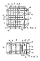
- a nuclear reactor fuel assembly grid 14 (see Figures 1 and 7) is manufactured by the welding together of grid straps 12.
- the grid 14 generally is of an approximately square configuration with the grid straps 12 fixedly disposed in an egg-crate array.
- Four outer grid straps 12a form the periphery of the grid 14 while inner grid straps 12b with mating slots are interleaved providing points of intersection 15.
- the outer grid straps 12a are generally wider and thicker than the inner grid straps 12b.
- Each end of an outer grid strap 12a is welded by a corner seam weld to the end of a perpendicularly disposed outer grid strap.
- the inner grid straps 12b are welded together at their points of intersection 15.
- the inner grid straps 12b have tabs at each end which mate with slits in the outer grid straps 12a. Tab and slit welds join together the outer grid straps 12a and the inner grid straps 12b.
- a computer-controlled precision laser welding apparatus (not shown) controls the welding beam and the positioning of the welding platform.
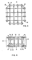
- the grid welding fixture 10 of the invention which would be mounted on the welding platform, properly positions the grid straps 12 in the desired egg-crate array for their welding together into a grid 14.
- the grid welding fixture 10 has a rigid bottom member 16, a rigid top member 26, and means for releasably securing the bottom member 16 and the top member 26 rigidly together.
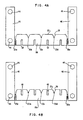
- the bottom member 16 has a number of interleaved bottom fixture straps 18 (see Figures 3, 4A and 4B) which are fixedly arranged in an egg-crate configuration (see Figure 1).
- a first set of elongated, spaced-apart, parallel bottom fixture straps has each of its straps 18a (see Figure 4B) with interleavable top slits 48.
- a second set of elongated, spaced-apart, parallel bottom fixture straps has each of its straps 18b (see Figure 4A) with interleavable bottom slits 50.
- the second set of straps 18b is rotated 90° and lowered to perpendicularly interweave with the first set of straps 18a by the engagement of the top slits 48 with the bottom slits 50.
- These bottom fixture straps 18a and 18b are secured together by welding.
- the top edges 22 of the bottom fixture straps 18 have top alignment notches 20 which are located to engage the bottom edges 24 of the grid straps 12 when the latter are in proper alignment for welding together into a grid 14.
- the top member 26 has a number of interleaved top fixture straps 28 (see Figures 3 and 5), which are fixedly arranged in an egg-crate configuration (see Figures 1 and 3) in a manner similar to that previously discussed for the bottom fixture straps 18.
- the bottom edges 32 of the top fixture straps 28 have bottom alignment notches 30 which are located to engage the top edges 34 of the grid straps 12 when the latter are in proper alignment for welding together into a grid 14.
- a top fixture strap assemblage is identical to a bottom fixture strap assemblage which has been turned upside down.
- the top notches 20 are located such that a line segment connecting any two adjacent top notches (e.g. 20a and 20b, 20b and 20c, etc. in Figure 4B) on any one bottom fixture strap (e.g. 18a) is generally perpendicularly bisected by a corresponding interleaved other bottom fixture strap (e.g. 18b in Figure 4A).
- the bottom notches 30 preferably are located such that a line segment connecting any two adjacent bottom notches 30 on any one top fixture strap 28 is generally perpendicularly bisected by a corresponding interleaved other top fixture strap. This will generally position the top and bottom weldable points of intersection 15 of any two interleaved grid straps in the middle of a top and a bottom square cell array of surrounding fixture straps which provides such points of intersection 15 with ready access for beam welding.
- each top notch 20 has at least one side with a lead-in chamfered upper portion 36 and each bottom notch 30 has at least one side with a lead-in chamfered lower portion 38 to help guide in the edges 32 and 22 of the grid straps 12.
- the outermost top notches (e.g. 20a and 20e in Figure 4B) on each bottom fixture strap 18 are deeper and wider than the other top notches (e.g. 20b, 20c, and 20d in Figure 4B) on that bottom fixture strap 18.
- the outermost bottom notches 30 on each top fixture strap 28 are deeper and wider than the other bottom notches 30 on that top fixture strap 28.
- the securing means releasably secures the bottom member 16 and the top member 26 rigidly together when the grid straps 12 are engaged in the top 20 and bottom 30 notches.
- the securing means includes the bottom member 16 also having a number of vertically upward extending links 40, the top member 26 also having a number of vertically downward extending links 42, and means for releasably connecting each upward extending link's upper end to the top member 26 and each downward extending link's lower end to the bottom member 16 when the grid straps 12 are engaged in the top 20 and bottom 30 notches.
- each upward extending link 40 is integral with one end of an associated bottom fixture strap 18 and the upper end of each downward extending link 42 is integral with one end of an associated top fixture strap 28. It is desirable that the ends of each bottom fixture strap 18 have integral upward extending links 40 and the ends of each top fixture strap 28 have integral downward extending links 42.
- the upward extending links 40 define one side of the outermost top notches 20 of the bottom fixture straps 18 (see Figures 4A and 4B), and likewise the downward extending links 42 define one side of the outermost bottom notches 30 of the top fixture straps 28.
- the connecting means include the links 40 and 42 being positioned to define the sides of a cage-like square array surrounding the grid straps 12 when the grid straps 12 are engaged in the notches 20 and 30.
- the links 40 and 42 associated with each side of the square array have at least one set (and preferably two) of aligned holes 44.
- a pin 46 slidably engages a corresponding set of aligned holes 44.
- Other connecting means include standard mechanical fastening techniques, known to those skilled in the art, such as bolts, clamps, or ohook and latch mechanisms on several pairs of adjacent upward extending and downward extending links, and the like.
- securing means includes "C"-type clamps on peripheral flanges of the top and bottom member fixture straps (without any links), bolts secured against mounting plates of the top and bottom member fixture straps, and any standard mechanical, releasable attaching devices; as is known to those skilled in the art.
- the fixture straps 18 and 28 are made by machining or punching or the like from strap stock as desired.
- Fixture strap material includes tool steel, stainless steel, and the like. These fixture straps are welded or brazed at their intersects to form the bottom 16 or top 26 member of the grid welding fixture 10.
- a short pin or button could engage aligned holes in each outermost pair of upward extending 40 and downward extending 42 links with the other intervening links being devoid of holes.
- the grid welding fixture 10 can be sized to accommodate any grid configuration such as a 4 x 4 grid (4 rows and 4 columns of nuclear fuel rods), a 16 x 16 grid, etc.
- the links 40 (and 42) are offset from their fixture strap 18 (and 28) such that opposing upward extending 40 and downward extending 42 links are touching (or nearly touching) when the top fixture member 26 is secured to the bottom fixture member 16.
- the bottom edges 24 of some grid straps 12 are alignably engaged in the top notches 20 of the bottom fixture straps 18 of the bottom member 16 to form a first parallel set. Then more grid straps 12 are perpendicularly interleaved with the grid straps of the first parallel set and guided to have their bottom edges 24 alignably engaged in the remaining top notches 20 of the bottom fixture straps 18.
- the top member 26 is then lowered, and the grid strap's top edges 34 are guided into the bottom notches 30 of the top fixture straps 28.
- a separate pin 46 is slidably engaged in each set of aligned holes 44.
- the grid straps 12 are now held in the grid welding fixture 10 to be welded into a grid 14. After welding, the grid welding fixture 10 is disassembled and the welded grid 14 obtained by removal of the pins 46 and then by separation of the bottom 16 and top 26 members.
Landscapes
- Physics & Mathematics (AREA)
- Engineering & Computer Science (AREA)
- Optics & Photonics (AREA)
- Plasma & Fusion (AREA)
- Mechanical Engineering (AREA)
- General Engineering & Computer Science (AREA)
- High Energy & Nuclear Physics (AREA)
- Butt Welding And Welding Of Specific Article (AREA)
- Laser Beam Processing (AREA)
- Structure Of Emergency Protection For Nuclear Reactors (AREA)
Applications Claiming Priority (2)
| Application Number | Priority Date | Filing Date | Title |
|---|---|---|---|
| US06/517,496 US4556776A (en) | 1983-07-26 | 1983-07-26 | Welding fixture for nuclear reactor fuel assembly grid |
| US517496 | 1995-08-21 |
Publications (2)
| Publication Number | Publication Date |
|---|---|
| EP0134920A1 EP0134920A1 (en) | 1985-03-27 |
| EP0134920B1 true EP0134920B1 (en) | 1987-10-28 |
Family
ID=24060056
Family Applications (1)
| Application Number | Title | Priority Date | Filing Date |
|---|---|---|---|
| EP84106854A Expired EP0134920B1 (en) | 1983-07-26 | 1984-06-15 | Welding fixture for nuclear reactor fuel assembly grid |
Country Status (7)
| Country | Link |
|---|---|
| US (1) | US4556776A (es) |
| EP (1) | EP0134920B1 (es) |
| JP (1) | JPS6042692A (es) |
| KR (1) | KR920003191B1 (es) |
| DE (1) | DE3466944D1 (es) |
| ES (1) | ES296423Y (es) |
| ZA (1) | ZA844730B (es) |
Families Citing this family (10)
| Publication number | Priority date | Publication date | Assignee | Title |
|---|---|---|---|---|
| GB8520844D0 (en) * | 1985-08-20 | 1985-09-25 | Sun Ind Coatings | Holding electrical/electronic components |
| US4873051A (en) * | 1988-04-06 | 1989-10-10 | Westinghouse Electric Corp. | Nuclear fuel grid outer strap |
| JPH02134000A (ja) * | 1988-11-15 | 1990-05-23 | Matsushita Electric Ind Co Ltd | 多品種対応プリント基板保持方法 |
| US5519747A (en) * | 1994-10-04 | 1996-05-21 | General Electric Company | Apparatus and methods for fabricating spacers for a nuclear fuel rod bundle |
| FR2736191B1 (fr) * | 1995-06-29 | 1997-09-26 | Franco Belge Combustibles | Procede et installation de soudage d'une grille-entretoise d'un assemblage de combustible pour un reacteur nucleaire et dispositif de soudage par l'interieur d'une grille |
| EP1858029B1 (en) * | 2006-05-19 | 2010-08-11 | Korea Atomic Energy Research Institute | Apparatus and method for welding strap connections between inner grid straps of spacer grid using laser tool, and spacer grid manufactured using the same |
| WO2014152851A2 (en) | 2013-03-14 | 2014-09-25 | Babcock & Wilcox Mpower, Inc. | Spacer grid welding fixtrue |
| DE102013105881A1 (de) * | 2013-06-06 | 2014-12-11 | Jenoptik Automatisierungstechnik Gmbh | Vorrichtungen zum Verbinden zweier Werkstückteile mittels Laser- Durchstrahlschweißen |
| CN105014288A (zh) * | 2015-08-20 | 2015-11-04 | 哈尔滨工业大学 | 用于核燃料组件定位格架的焊接夹具 |
| DE202019102247U1 (de) * | 2019-04-18 | 2019-04-30 | Zell Metalltechnik Gmbh | Gitterförmiger Werkstückträger |
Family Cites Families (9)
| Publication number | Priority date | Publication date | Assignee | Title |
|---|---|---|---|---|
| US3836135A (en) * | 1973-01-26 | 1974-09-17 | L Wightman | Plate spacing fixture for electrostatic air cleaners |
| GB1518311A (en) * | 1975-04-02 | 1978-07-19 | Atomic Energy Authority Uk | Welding jigs |
| US4101752A (en) * | 1976-09-15 | 1978-07-18 | Westinghouse Electric Corp. | Process for welding corner cells in fuel assembly grids |
| US4137125A (en) * | 1976-11-12 | 1979-01-30 | Westinghouse Electric Corp. | Method of welding nuclear reactor fuel assemblies |
| US4291218A (en) * | 1976-12-20 | 1981-09-22 | Myhre Kjell E | Transducer diaphragm elements and methods and apparatus for making same |
| US4132396A (en) * | 1978-04-06 | 1979-01-02 | Graham George W | Glueing clamp assembly |
| US4286778A (en) * | 1979-11-07 | 1981-09-01 | Follmeyer Fred R | Machining fixtures |
| FR2522560A1 (fr) * | 1982-03-03 | 1983-09-09 | Commissariat Energie Atomique | Procede et dispositif pour la realisation par soudage laser par impulsions d'elements de structure de reacteurs nucleaires et grilles en alliage de zirconium obtenues par ce procede |
| US4492844A (en) * | 1982-09-01 | 1985-01-08 | Westinghouse Electric Corp. | Welding plates for a fuel rod grid |
-
1983
- 1983-07-26 US US06/517,496 patent/US4556776A/en not_active Expired - Fee Related
-
1984
- 1984-06-15 EP EP84106854A patent/EP0134920B1/en not_active Expired
- 1984-06-15 DE DE8484106854T patent/DE3466944D1/de not_active Expired
- 1984-06-21 ZA ZA844730A patent/ZA844730B/xx unknown
- 1984-07-23 JP JP59151473A patent/JPS6042692A/ja active Granted
- 1984-07-23 ES ES1984296423U patent/ES296423Y/es not_active Expired
- 1984-07-23 KR KR1019840004374A patent/KR920003191B1/ko active IP Right Grant
Also Published As
| Publication number | Publication date |
|---|---|
| KR850001049A (ko) | 1985-03-14 |
| US4556776A (en) | 1985-12-03 |
| ES296423U (es) | 1987-09-01 |
| ZA844730B (en) | 1985-02-27 |
| DE3466944D1 (en) | 1987-12-03 |
| JPS6042692A (ja) | 1985-03-06 |
| JPS6344480B2 (es) | 1988-09-05 |
| ES296423Y (es) | 1988-04-16 |
| KR920003191B1 (ko) | 1992-04-24 |
| EP0134920A1 (en) | 1985-03-27 |
Similar Documents
| Publication | Publication Date | Title |
|---|---|---|
| EP0514120B1 (en) | Swirl vanes in inconel spacer | |
| EP0134920B1 (en) | Welding fixture for nuclear reactor fuel assembly grid | |
| JPH029550B2 (es) | ||
| KR100338912B1 (ko) | 원자로내에서연료봉을지지하기위한격자구조체 | |
| US3255091A (en) | Fuel arrangement for a nuclear reactor | |
| JPS61184487A (ja) | 燃料棒の間隔および位置保持装置 | |
| EP0456055A1 (en) | Modified cross point spacer apparatus and construction | |
| JPH029552B2 (es) | ||
| US4714585A (en) | Interlocking egg-crate type grid assembly | |
| US4090918A (en) | Spacer structure | |
| EP0103444B1 (en) | Fuel grid with sleeves welded in notched grid straps | |
| US4522330A (en) | Grid and sleeves welding fixture and method | |
| US4711436A (en) | Grid assembly fixture, retention strap and method | |
| EP0528333B1 (en) | Boiling water reactor fuel rod assembly with fuel rod spacer arrangement | |
| US4762676A (en) | Top nozzle adapter plate with fuel rod capture grid having pressure drop adjusting means | |
| EP1402538B1 (en) | Integrally fastened spacer for grid of a nuclear reactor with associated method | |
| EP0762430A1 (en) | Reduced height flat spring spacer for nucelar fuel rods | |
| JP2650092B2 (ja) | 原子炉用燃料集合体の支持格子 | |
| KR910001978B1 (ko) | 일체 베인을 가진 지지 그리드 | |
| US4351795A (en) | Grids for nuclear fuel assemblies | |
| JPH08170994A (ja) | ばねアセンブリ、一対のフェルールと組み合わせたばねアセンブリ、スペーサ集合体、ばね、及び一対の隣接したフェルールと組み合わせたばね | |
| US5084237A (en) | Side insertable spacer | |
| US4519593A (en) | Grid assembly fixture, retention strap | |
| US5188798A (en) | Grid for nuclear fuel assembly | |
| US4725402A (en) | Welded nuclear fuel grid and method |
Legal Events
| Date | Code | Title | Description |
|---|---|---|---|
| PUAI | Public reference made under article 153(3) epc to a published international application that has entered the european phase |
Free format text: ORIGINAL CODE: 0009012 |
|
| AK | Designated contracting states |
Designated state(s): BE CH DE FR GB IT LI SE |
|
| 17P | Request for examination filed |
Effective date: 19850816 |
|
| 17Q | First examination report despatched |
Effective date: 19860903 |
|
| ITF | It: translation for a ep patent filed | ||
| GRAA | (expected) grant |
Free format text: ORIGINAL CODE: 0009210 |
|
| AK | Designated contracting states |
Kind code of ref document: B1 Designated state(s): BE CH DE FR GB IT LI SE |
|
| REF | Corresponds to: |
Ref document number: 3466944 Country of ref document: DE Date of ref document: 19871203 |
|
| ET | Fr: translation filed | ||
| PLBE | No opposition filed within time limit |
Free format text: ORIGINAL CODE: 0009261 |
|
| STAA | Information on the status of an ep patent application or granted ep patent |
Free format text: STATUS: NO OPPOSITION FILED WITHIN TIME LIMIT |
|
| 26N | No opposition filed | ||
| PGFP | Annual fee paid to national office [announced via postgrant information from national office to epo] |
Ref country code: FR Payment date: 19920318 Year of fee payment: 9 |
|
| PGFP | Annual fee paid to national office [announced via postgrant information from national office to epo] |
Ref country code: SE Payment date: 19920323 Year of fee payment: 9 Ref country code: GB Payment date: 19920323 Year of fee payment: 9 |
|
| PGFP | Annual fee paid to national office [announced via postgrant information from national office to epo] |
Ref country code: BE Payment date: 19920402 Year of fee payment: 9 |
|
| PGFP | Annual fee paid to national office [announced via postgrant information from national office to epo] |
Ref country code: DE Payment date: 19920630 Year of fee payment: 9 |
|
| PGFP | Annual fee paid to national office [announced via postgrant information from national office to epo] |
Ref country code: CH Payment date: 19920710 Year of fee payment: 9 |
|
| PG25 | Lapsed in a contracting state [announced via postgrant information from national office to epo] |
Ref country code: GB Effective date: 19930615 |
|
| PG25 | Lapsed in a contracting state [announced via postgrant information from national office to epo] |
Ref country code: SE Effective date: 19930616 |
|
| PG25 | Lapsed in a contracting state [announced via postgrant information from national office to epo] |
Ref country code: LI Effective date: 19930630 Ref country code: CH Effective date: 19930630 Ref country code: BE Effective date: 19930630 |
|
| BERE | Be: lapsed |
Owner name: WESTINGHOUSE ELECTRIC CORP. Effective date: 19930630 |
|
| GBPC | Gb: european patent ceased through non-payment of renewal fee |
Effective date: 19930615 |
|
| PG25 | Lapsed in a contracting state [announced via postgrant information from national office to epo] |
Ref country code: FR Effective date: 19940228 |
|
| REG | Reference to a national code |
Ref country code: CH Ref legal event code: PL |
|
| PG25 | Lapsed in a contracting state [announced via postgrant information from national office to epo] |
Ref country code: DE Effective date: 19940301 |
|
| REG | Reference to a national code |
Ref country code: FR Ref legal event code: ST |
|
| EUG | Se: european patent has lapsed |
Ref document number: 84106854.7 Effective date: 19940110 |