EP0134737B1 - Submarine suction cup of the low pressure by suction type - Google Patents
Submarine suction cup of the low pressure by suction type Download PDFInfo
- Publication number
- EP0134737B1 EP0134737B1 EP19840401515 EP84401515A EP0134737B1 EP 0134737 B1 EP0134737 B1 EP 0134737B1 EP 19840401515 EP19840401515 EP 19840401515 EP 84401515 A EP84401515 A EP 84401515A EP 0134737 B1 EP0134737 B1 EP 0134737B1
- Authority
- EP
- European Patent Office
- Prior art keywords
- wall
- suction cup
- underwater
- skirt
- watertightness
- Prior art date
- Legal status (The legal status is an assumption and is not a legal conclusion. Google has not performed a legal analysis and makes no representation as to the accuracy of the status listed.)
- Expired
Links
Images


Classifications
-
- B—PERFORMING OPERATIONS; TRANSPORTING
- B63—SHIPS OR OTHER WATERBORNE VESSELS; RELATED EQUIPMENT
- B63C—LAUNCHING, HAULING-OUT, OR DRY-DOCKING OF VESSELS; LIFE-SAVING IN WATER; EQUIPMENT FOR DWELLING OR WORKING UNDER WATER; MEANS FOR SALVAGING OR SEARCHING FOR UNDERWATER OBJECTS
- B63C7/00—Salvaging of disabled, stranded, or sunken vessels; Salvaging of vessel parts or furnishings, e.g. of safes; Salvaging of other underwater objects
- B63C7/16—Apparatus engaging vessels or objects
- B63C7/22—Apparatus engaging vessels or objects using electromagnets or suction devices
Definitions
- the technical sector of the present invention is that of underwater works, and more particularly devices aimed at producing solid attachment points on an underwater wall.
- Suction cups of different types have been used for a long time to achieve these solid support points.
- the first principle is generally used for the fixing and the maintenance of the explosive charges of destruction but their effectiveness is limited in time (and strongly depends on the care brought to their installation) and their force of adhesion is rather weak. They also require a surface cleaned beforehand.
- the second principle is used for the attachment of robots or machining systems.
- the magnetic suction cups are not very effective, require careful cleaning of the magnetic walls and their weight allows only horizontal applications downwards.
- the third principle is also unsatisfactory since it is not very effective due to the absence of skirts. In addition, this is heavy and bulky equipment.
- a last principle (FR-A-2 071 477) consists in using suction cups of the vacuum type maintained by a permanent pumping means for possible leaks, corresponding to a suction cup according to the preamble of claim 1.
- the object of the invention is to provide a suction cup of the latter type (with maintained vacuum) which is portable, therefore of low weight, but retains a large autonomy without the addition of energy or fluid from a carrier boat.
- a feature of the invention is to include the batteries and the motor 2 driving the pump 9 inside a sealed enclosure 7 without opening towards the pump, which ensures better sealing of the electrical circuit and batteries, this being permitted by virtue of the motor-pump connection produced through the sealed wall of the enclosure 7 without opening of the latter by means of a magnetic coupling.
- the skirt is made of neoprene.
- the sealing skirt 10 is a single-walled skirt, interchangeable.
- the sealing skirt 10 has a double wall with a profile suitable for holding plates before welding, the wall with internal profile 13 being longer than the external wall 12 and the two walls each having a variation. 19 in their length over part of their circumference, the variation in length being a function of the thickness of the plate to be welded,
- the sealing skirt 10 is double-walled, the profile of which is suitable for lifting spherical objects, the internal wall 13 being either shorter or the same length as the external wall 12 and the skirt 10 being interchangeable according to the extent of the variation in the diameters of the various spherical objects to be lifted.
- Another object of the invention is to provide an autonomous device for assisting the progression underwater of a diver along a wall despite the presence of significant sea currents, the device comprising two suction cups according to the invention used alternately.
- the suction cups may include a means of simultaneous action of stopping the engine and putting the vacuum bell of the suction cup at ambient pressure.
- Another object of the invention is to achieve by means of the suction cups according to the invention an underwater workshop comprising a platform allowing the laying of heavy loads or tools, this underwater workshop can be applied in any place under the hull of a ship by means of the aforementioned suction cups, to assist a diver carrying out repairs under the hull and ensuring off-shore work.
- the underwater suction cup can include a safety device triggering the operation of the pump 9 at a predetermined depth.
- the underwater suction cup is presented according to FIG. 1.
- the sealed enclosure 7 of the suction cup contains the pump 9 and the motor 2, the drive of the pump 9 by the motor 2 being done by means of the magnetic coupling 8.
- the motor is started manually using the contactor 4, and thanks to the safety device 11 (see fig. 2 and 9) triggering at a predetermined depth.
- the contactor 4 is engaged, the motor 2 is supplied, either by the internal batteries 3, or by means of the external power connector 6.
- a vacuum by suction is then created in the bell formed by the skirt 10, the pump 9 being provided with exhaust 1.
- This pump 9 differs from vacuum pumps by air suction in the following way: it works by only sucking water, which is also its lubricating liquid and can maintain a significant vacuum inside of the bell formed by the skirt 10, even in the absence of flow. Sealing is achieved thanks to the neoprene skirt 10. A skirt holder allows its interchangeability. Finally, to allow good maneuverability of the suction cup by divers, it is provided with a handle 5.
- the underwater suction cup according to the second variant is presented according to FIG. 5.
- the skirt is provided with two walls 12 and 13 substantially of the same length, which makes it possible to obtain a better seal in the case where one of the two skirts would be badly positioned.
- the wall 13 is longer than the wall 12 (see for example the right part of FIG. 7).
- the plunger by applying the suction cup against an underwater wall, only brings the wall into contact with the latter 13. Adhesion is then achieved, but the wall 13 may not be perfectly positioned and leaks remain .
- the plunger having released the handle 5, can then perfectly position the wall 12, the latter not having yet adhered to the underwater wall.
- This principle has the enormous advantage of avoiding the diver during an imperfect adhesion to the wall 12, having to start the whole maneuver again, and having a perfect seal, the plunger having all the time necessary to perform positioning. wall 12.
- the skirt shown in Figure 7 is provided with a wall 13 longer than the wall 12.
- the variant of the underwater suction cup shown in Figure 7 is also suitable for holding plates before welding.
- the two walls, of unequal length each have a variation in their length over part of their circumference. This variation corresponds to the thickness of the plate to be welded and can range, while guaranteeing a perfect seal, up to a maximum of 12 mm.
- Figure 6 shows the variant of an underwater suction cup suitable for lifting spherical objects.
- the two walls 12 and 13 are of different length, the wall 12 being longer than the wall 13 so that the end of the two walls is arranged on the same sphere.
- the adhesion of the two walls will be carried out in a perfect manner, the end of the two walls also being bevelled to allow total sealing.
- the wall 13 will adhere first, thus allowing the plunger to perfectly position the wall 12.
- the basic principle of the underwater suction cup can be adapted as required.
- the device shown in FIG. 8 comprises a single vacuum pump 9 connected by means of flexible pipes 15 to different vacuum chambers provided with single or double walled sealing skirts.
- the suction cups are connected together by a rigid frame 14. This device allows for example to fix along an underwater hull a cleaning robot or other automatic mechanisms.
- specific skirts can be adapted to each particular case.
- FIG. 9 shows the safety device triggering the pump at a certain depth.
- This device is composed of a plate with holes 16 in which the water establishes a pressure acting on the membrane 17. The latter, by deforming, will establish contact at a certain pressure corresponding to a predetermined immersion depth, with relay 18 connected in series in the control circuit between the contactor and the motor. Thus the engine will be started and the pump will come into action.
- the suction cup In lateral traction, the suction cup is pulled out between 50 daN and 100 daN depending on the surface condition.
- FIGS 10 and 11 show a variant of space-saving suction cup which can be intended to aid the progression of a diver along a boat hull in the presence of a sea current.
- the control means 20 is made in the form of an on / off switch 22 for the motor 2, actuated by a sealed push button 23 acting against a spring 24, the push button 23 being integral with a rod 25 operating a valve 21 which allows, by pressing on the pusher, to put the interior of the vacuum bell 10 into communication with the marine environment through an adjustment 26.
- the batteries 3 for supplying the engine 2 may not be placed inside the sealed enclosure 7 but be placed on the compressed air bottles 27 of the plunger (see FIG. 12). , the batteries 3 then being connected to the motor 2 by cables 28.
- the invention allows the realization of an autonomous means of assistance with the progression under water of a plunger along a wall against currents of 1 to 2 knots.
- the diver holds in each hand a suction cup carrying a built-in battery or connected by a cable 28 to a battery 3 supported by its compressed air bottles.
- the plunger presses a suction cup against the wall by releasing the control means 20; the pump then operates while the vacuum bell is closed by the valve 21 and the suction cup becomes vacuum.
- the diver places a second suction cup further on the wall and detaches the first suction cup by pressing on the control means 20, which has the effect of stopping the motor 2 and putting the bell 10 and the sea in communication .
- Lightened suction cups weighing less than 3 daN made according to the invention thus made it possible for a diver to progress or work with an autonomy of more than an hour in currents of 2 knots.
- an underwater workshop is produced by means of a platform scaffolding 30 comprising expandable horizontal and vertical tubes 31 at the end of which suction cups 33 can be arranged according to the invention.
- the suction cups 33 are arranged at the end of the horizontal or vertical tubes 31, depending on the inclination of the hull or of the wall on which the underwater workshop is to be fixed. To allow better adaptability of the assembly, the suction cups are mounted to rotate on the arms 31 by means of rotation axes 32.
- the load capacity of the platform 30 is under water of 1,000 daN with an autonomy of one hour.
- external batteries can be used on the carrier boat to which the suction cups 33 will be connected.
- the submarine workshop thus produced has an important advantage compared to previous achievements which were fixed under the ship using two straps passed from one edge to the other.
- the implementation time of these prior devices required approximately four hours of work for two divers and three men on board while the device according to the present invention requires only half an hour of work for 2 divers and a man of edge.
Landscapes
- Physics & Mathematics (AREA)
- Electromagnetism (AREA)
- Engineering & Computer Science (AREA)
- Mechanical Engineering (AREA)
- Ocean & Marine Engineering (AREA)
- Manipulator (AREA)
- Toys (AREA)
Description
Le secteur technique de la présente invention est celui des travaux sous-marins, et plus particulièrement des dispositifs visant à réaliser des points d'accrochage solides sur une paroi sous-marine.The technical sector of the present invention is that of underwater works, and more particularly devices aimed at producing solid attachment points on an underwater wall.
Dans le domaine des travaux sous-marins, les plongeurs se sont toujours heurtés au problème, pourtant essentiel, de se fixer solidement sur une paroi pour y effectuer des travaux par exemple de soudage, de perçage, ou encore de fixation de tape pour l'évacuation de produits contenus dans des cuves.In the field of underwater works, divers have always come up against the problem, however essential, of fixing themselves firmly on a wall to carry out work there, for example welding, drilling, or even fixing tape for the evacuation of products contained in tanks.
On utilise depuis longtemps des ventouses de différents types pour réaliser ces points d'appuis solides. Les types de réalisations antérieures connus sont au nombre de trois : les ventouses statiques sous-marines, les ventouses magnétiques et les ventouses magnétiques entretenues.Suction cups of different types have been used for a long time to achieve these solid support points. There are three types of prior known embodiments: underwater static suction cups, magnetic suction cups and maintained magnetic suction cups.
Le premier principe est en général utilisé pour la fixation et le maintien des charges explosives de destruction mais leur efficacité est limitée dans le temps (et dépend fortement du soin apporté à leur pose) et leur force d'adhésion est assez faible. Elles exigent en outre une surface nettoyée au préalable.The first principle is generally used for the fixing and the maintenance of the explosive charges of destruction but their effectiveness is limited in time (and strongly depends on the care brought to their installation) and their force of adhesion is rather weak. They also require a surface cleaned beforehand.
Le second principe est utilisé pour la fixation de robots ou de systèmes d'usinages. Mais les ventouses magnétiques sont peu efficaces, demandent un nettoyage soigné des parois magnétiques et leur poids n'autorise que des applications horizontales vers le bas.The second principle is used for the attachment of robots or machining systems. However, the magnetic suction cups are not very effective, require careful cleaning of the magnetic walls and their weight allows only horizontal applications downwards.
Le troisième principe est également insatisfaisant car peu efficace du fait de l'absence de jupes. De plus, il s'agit là de matériel lourd et encombrant.The third principle is also unsatisfactory since it is not very effective due to the absence of skirts. In addition, this is heavy and bulky equipment.
Un dernier principe (FR-A-2 071 477) consiste à utiliser des ventouses du type à dépression entretenue par un moyen de pompage permanent des fuites éventuelles, correspondant à une ventouse selon le préambule de la revendication 1.A last principle (FR-A-2 071 477) consists in using suction cups of the vacuum type maintained by a permanent pumping means for possible leaks, corresponding to a suction cup according to the preamble of claim 1.
Les brevets US 2 347 491, US 2 876 026 et FR 2 071 477 décrivent des ventouses similaires. Toutefois, ils décrivent des dispositifs tous reliés à une alimentation externe disposée sur un bateau porteur, les ventouses elles-mêmes étant de gros volume pour permettre avec seulement trois ou quatre ventouses d'assurer le renfloue- ment du navire. Ces dispositifs ne sont pas autonomes et ne sont pas portables par un plongeur.US Patents 2,347,491, US 2,876,026 and FR 2,071,477 describe similar suction cups. However, they describe devices all connected to an external power supply arranged on a carrier boat, the suction cups themselves being of large volume to allow with only three or four suction cups to ensure the refloating of the ship. These devices are not autonomous and are not portable by a diver.
L'invention a pour but de fournir une ventouse de ce dernier type (à dépression entretenue) qui soit portable, donc de faible poids, mais conserve une grande autonomie sans apport d'énergie ou de fluide à partir d'un bateau porteur.The object of the invention is to provide a suction cup of the latter type (with maintained vacuum) which is portable, therefore of low weight, but retains a large autonomy without the addition of energy or fluid from a carrier boat.
L'invention vise donc à obtenir, tout en évitant les inconvénients cités, une fixation efficace le long d'une paroi immergée. Le point d'accrochage solide sera réalisé par une ventouse sous-marine, du type à dépression entretenue par un moyen de pompage permanent des fuites éventuelles selon le préambule de la revendication 1. Selon l'invention, la ventouse comprend :
- - une enceinte étanche contenant les batteries, le circuit électrique et le moteur d'entraînement ;
- - un accouplement magnétique d'entraînement de la pompe par le moteur au travers de la paroi étanche de l'enceinte.
- - a sealed enclosure containing the batteries, the electrical circuit and the drive motor;
- - a magnetic coupling for driving the pump by the motor through the sealed wall of the enclosure.
Une particularité de l'invention est de comporter les batteries et le moteur 2 d'entraînement de la pompe 9 à l'intérieur d'une enceinte étanche 7 sans ouverture vers la pompe, ce qui permet d'assurer une meilleure étanchéité du circuit électrique et des batteries, ceci étant permis grâce à la liaison moteur-pompe réalisée au travers de la paroi étanche de l'enceinte 7 sans ouverture de celle-ci au moyen d'un accouplement magnétique.A feature of the invention is to include the batteries and the
De préférence, la jupe est réalisée en néoprène.Preferably, the skirt is made of neoprene.
Selon une première variante la jupe d'étanchéité 10 est une jupe à simple paroi, interchangeable.According to a first variant, the sealing
Dans une application de l'invention, la jupe d'étanchéité 10 est à double paroi à profil adapté au maintien de plaques avant soudure, la paroi à profil interne 13 étant plus longue que la paroi externe 12 et les deux parois présentant chacune une variation 19 dans leur longueur sur une partie de leur circonférence, la variation de longueur étant fonction de l'épaisseur de la plaque à souder,In one application of the invention, the
Dans une autre application de l'invention, la jupe d'étanchéité 10 est à double paroi dont le profil est adapté au levage d'objets sphériques, la paroi interne 13 étant soit plus courte soit de même longueur que la paroi externe 12 et la jupe 10 étant interchangeable en fonction de l'importance de la variation des diamètres des différents objets sphériques à lever.In another application of the invention, the
Un autre objet de l'invention est de fournir un dispositif autonome d'aide à la progression sous l'eau d'un plongeur le long d'une paroi malgré la présence de courants marins importants, le dispositif comportant deux ventouses selon l'invention utilisées alternativement.Another object of the invention is to provide an autonomous device for assisting the progression underwater of a diver along a wall despite the presence of significant sea currents, the device comprising two suction cups according to the invention used alternately.
Dans ce cas, les ventouses peuvent comporter un moyen d'action simultané de l'arrêt du moteur et de la mise à pression ambiante de la cloche à dépression de la ventouse.In this case, the suction cups may include a means of simultaneous action of stopping the engine and putting the vacuum bell of the suction cup at ambient pressure.
Un autre objet de l'invention est de réaliser au moyen des ventouses selon l'invention un atelier sous-marin comportant une plate-forme permettant la pose de charges lourdes ou d'outillages, cet atelier sous-marin pouvant être appliqué en un quelconque endroit sous la coque d'un navire au moyen des ventouses précitées, pour assister un plongeur effectuant des réparations sous la coque et assurant un travail off-shore.Another object of the invention is to achieve by means of the suction cups according to the invention an underwater workshop comprising a platform allowing the laying of heavy loads or tools, this underwater workshop can be applied in any place under the hull of a ship by means of the aforementioned suction cups, to assist a diver carrying out repairs under the hull and ensuring off-shore work.
Enfin, une autre particularité de l'invention est que la ventouse sous-marine peut comporter un dispositif de sécurité déclenchant le fonctionnement de la pompe 9 à une profondeur prédéterminée.Finally, another feature of the invention is that the underwater suction cup can include a safety device triggering the operation of the pump 9 at a predetermined depth.
L'invention sera illustrée à l'aide de la description détaillée qui suit d'un mode de réalisation donné à titre d'exemple non limitatif, en référence aux dessins sur lesquels :
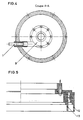
- la figure 1 montre la ventouse en coupe longitudinale selon la première variante, c'est-à-dire munie d'une jupe en néoprène à simple paroi ;
- la figure 2 montre la ventouse de dessus suivant F, munie de son couvercle ;
- la figure 3 montre la ventouse de dessus suivant F, sans son couvercle :
- la figure 4 montre la ventouse selon la coupe A-A de la figure 1 ;
- la figure 5 montre un détail de la ventouse en coupe longitudinale selon la seconde variante, c'est-à-dire munie d'une jupe en néoprène à double paroi ;
- la figure 6 montre une jupe à double paroi adaptée au cas particulier du levage d'objets sphériques ;
- la figure 7 montre une jupe à double paroi à profil spécial adaptée au cas particulier de maintien d'une plaque avant soudure ;
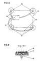
- la figure 8 schématise une centrale de dépression avec des ventouses séparées pour la fixation de matériels importants ;
- la figure 9 montre un dispositif de sécurité selon la coupe C-C de la figure 2 ;
- la figure 10 représente en coupe un autre mode de réalisation de la ventouse selon l'invention de forme moins volumineuse ;
- la figure 11 montre en coupe partielle AA de la figure 10 le détail du moyen d'actionnement simultané de l'arrêt du moteur et de la mise à pression ambiante de la cloche à dépression ;
- la figure 12 montre l'application de telles ventouses à la progression d'un plongeur le long d'une paroi et
- la figure 13 montre l'application des ventouses selon l'invention à la réalisation d'ateliers sous-marins.
- Figure 1 shows the suction cup in longitudinal section according to the first variant, that is to say provided with a single wall neoprene skirt;
- FIG. 2 shows the upper suction cup along F, fitted with its cover;
- FIG. 3 shows the upper suction cup along F, without its cover:
- Figure 4 shows the suction cup according to section AA of Figure 1;
- Figure 5 shows a detail of the suction cup in longitudinal section according to the second variant, that is to say provided with a double-walled neoprene skirt;
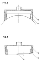
- Figure 6 shows a double-walled skirt suitable for the specific case of lifting spherical objects;
- FIG. 7 shows a double-walled skirt with a special profile adapted to the particular case of holding a plate before welding;
- Figure 8 shows schematically a central vacuum with separate suction cups for fixing important equipment;
- Figure 9 shows a safety device according to section CC of Figure 2;
- FIG. 10 shows in section another embodiment of the suction cup according to the invention of less bulky shape;
- FIG. 11 shows in partial section AA of FIG. 10 the detail of the means for simultaneously actuating the stopping of the engine and the setting of the vacuum bell at ambient pressure;
- FIG. 12 shows the application of such suction cups to the progression of a plunger along a wall and
- FIG. 13 shows the application of the suction cups according to the invention to the production of underwater workshops.
La ventouse sous-marine, d'après la première variante, se présente selon la figure 1. L'enceinte étanche 7 de la ventouse contient la pompe 9 et le moteur 2, l'entraînement de la pompe 9 par le moteur 2 se faisant au moyen de l'accouplement magnétique 8. Le moteur est mis en route manuellement à l'aide du contacteur 4, et grâce au dispositif de sécurité 11 (voir fig. 2 et 9) se déclenchant à une profondeur prédéterminée. Une fois le contacteur 4 enclenché, le moteur 2 est alimenté, soit par les batteries internes 3, soit à l'aide du connecteur d'alimentation extérieur 6. Une dépression par aspiration se crée alors dans la cloche formée par la jupe 10, la pompe 9 étant munie de l'échappement 1.The underwater suction cup, according to the first variant, is presented according to FIG. 1. The sealed
Cette pompe 9 se différencie des pompes à dépression par aspiration d'air de la manière suivante : elle ne fonctionne en n'aspirant que de l'eau, qui est en outre son liquide de lubrification et peut maintenir une dépression importante à l'intérieur de la cloche formée par la jupe 10, même en l'absence de débit. L'étanchéité est réalisée grâce à la jupe en néoprène 10. Un porte- jupe permet son interchangeabilité. Enfin, pour permettre une bonne maniabilité de la ventouse par les plongeurs, celle-ci est munie d'une poignée 5.This pump 9 differs from vacuum pumps by air suction in the following way: it works by only sucking water, which is also its lubricating liquid and can maintain a significant vacuum inside of the bell formed by the
La ventouse sous-marine d'après la seconde variante se présente selon la figure 5. La jupe est munie de deux parois 12 et 13 sensiblement de même longueur, ce qui permet d'obtenir une meilleure étanchéité dans le cas où l'une des deux jupes serait mal positionnée.The underwater suction cup according to the second variant is presented according to FIG. 5. The skirt is provided with two
Selon une autre variante, la paroi 13 est plus longue que la paroi 12 (voir par exemple la partie droite de la figure 7). Ainsi le plongeur, en appliquant la ventouse contre une paroi sous-marine, ne met en contact avec cette dernière que la paroi 13. Une adhérence est alors réalisée mais il se peut que la paroi 13 ne soit pas parfaitement positionnée et que des fuites subsistent. Le plongeur ayant lâché la poignée 5, peut alors positionner de manière parfaite la paroi 12, cette dernière n'ayant pas encore adhéré à la paroi sous-marine. Ce principe présente l'énorme avantage d'éviter au plongeur lors d'une adhérence imparfaite à la paroi 12, d'avoir à recommencer toute la manoeuvre, et présente une étanchéité parfaite, le plongeur disposant de tout le temps nécessaire pour effectuer un positionnement parfait de la paroi 12.According to another variant, the
La jupe représentée figure 7 est munie d'une paroi 13 plus longue que la paroi 12. Mais la variante de la ventouse sous-marine représentée figure 7 est en outre adaptée au maintien de plaques avant soudure. De ce fait, les deux parois, de longueur inégale, présentent chacune une variation dans leur longueur sur une partie de leur circonférence. Cette variation correspond à l'épaisseur de la plaque à souder et peut aller, tout en garantissant une étanchéité parfaite, jusqu'à un maximum de 12 mm.The skirt shown in Figure 7 is provided with a
La figure 6 représente la variante d'une ventouse sous-marine adaptée au levage d'objets sphériques. Les deux parois 12 et 13 sont de longueur différente, la paroi 12 étant plus longue que la paroi 13 de manière à ce que l'extrémité des deux parois soit disposée sur une même sphère. Ainsi, pour des objets sphériques d'un diamètre sensiblement égal, l'adhérence des deux parois sera réalisée de manière parfaite, l'extrémité des deux parois étant de plus, bisautée pour permettre une étanchéité totale. Il est également possible de prévoir une longueur identique des deux parois 12 et 13. Ainsi selon le principe précédent, la paroi 13 adhérera en premier, permettant ainsi au plongeur de positionner parfaitement la paroi 12.Figure 6 shows the variant of an underwater suction cup suitable for lifting spherical objects. The two
Il est également possible de procéder au levage d'objets sphériques de diamètre différent, grâce à l'interchangeabilité des jupes. Le principe de base de la ventouse sous-marine peut être adapté en fonction des besoins.It is also possible to lift spherical objects of different diameter, thanks to the interchangeability of the skirts. The basic principle of the underwater suction cup can be adapted as required.
Le dispositif représenté figure 8 comporte une pompe à dépression unique 9 reliée à l'aide de tuyaux flexibles 15 à différentes chambres à dépression munies des jupes d'étanchéité à simple ou double paroi. Les ventouses sont reliées entre elles grâce à un cadre rigide 14. Ce dispositif permet par exemple de fixer le long d'une coque sous-marine un robot de nettoyage ou d'autres mécanismes automatiques. En outre, des jupes spécifiques peuvent être adaptées à chaque cas particulier.The device shown in FIG. 8 comprises a single vacuum pump 9 connected by means of
La figure 9 enfin, représente le dispositif de sécurité déclenchant la pompe à une certaine profondeur. Ce dispositif est composé d'une plaque à trous 16 dans lesquels l'eau établit une pression agissant sur la membrane 17. Celle-ci, en se déformant, va établir le contact à une certaine pression correspondant à une profondeur d'immersion prédéterminée, avec le relais 18 mis en série dans le circuit de commande entre le contacteur et le moteur. Ainsi le moteur sera mis en route et la pompe entrera en action.Finally, FIG. 9 shows the safety device triggering the pump at a certain depth. This device is composed of a plate with
Les résultats acquis lors des essais en laboratoire et en milieu marin prouvent l'efficacité de ce dispositif. Les essais en milieu marin ont prouvé l'excellente tenue de la ventouse dynamique équipée d'une jupe double en néoprène dont le diamètre de la paroi externe est de 300 mm et le diamètre de la paroi interne est de 220 mm.The results acquired during laboratory and marine tests prove the effectiveness of this device. Tests in the marine environment have proven the excellent performance of the dynamic suction cup equipped with a double neoprene skirt, the diameter of the external wall is 300 mm and the diameter of the internal wall is 220 mm.
Après adhésion sur une paroi bétonnée brute de coffrage, la ventouse immergée à 1 m de profondeur a résisté à des tractions dans l'axe de 280 daN.After adhesion to a rough concrete formwork wall, the submerged suction cup 1 m deep resisted pulls in the axis of 280 daN.
En traction latérale, l'arrachage de la ventouse se réalise entre 50 daN et 100 daN suivant l'état de surface.In lateral traction, the suction cup is pulled out between 50 daN and 100 daN depending on the surface condition.
Les figures 10 et 11 montrent une variante de ventouse à faible encombrement qui peut être destinée à l'aide à la progression d'un plongeur le long d'une coque de bateau en présence d'un courant marin. Dans cette variante, le principe de fonctionnement est conservé mais peut être amélioré par la présence d'un moyen de commande 20 simultané de l'arrêt du pompage et de la mise à pression ambiante de la cloche à dépression 10. Le moyen de commande 20 est réalisé sous la forme d'un contacteur 22 de marche-arrêt du moteur 2, actionné par un bouton-poussoir étanche 23 agissant à l'encontre d'un ressort 24, le bouton-poussoir 23 étant solidaire d'une tige 25 manoeuvrant un clapet 21 qui permet par appui sur le poussoir, de mettre en communication l'intérieur de la cloche à dépression 10 et le milieu marin au travers d'un ajustage 26.Figures 10 and 11 show a variant of space-saving suction cup which can be intended to aid the progression of a diver along a boat hull in the presence of a sea current. In this variant, the operating principle is preserved but can be improved by the presence of a means for simultaneously controlling the stopping of the pumping and the setting of the
Dans une version allégée de cette variante, les batteries 3 d'alimentation du moteur 2 peuvent ne pas être disposées à l'intérieur de l'enceinte étanche 7 mais être placées sur les bouteilles d'air comprimé 27 du plongeur (voir figure 12), les batteries 3 étant alors reliées au moteur 2 par des câbles 28.In a light version of this variant, the
Au moyen de telles ventouses, l'invention permet la réalisation d'un moyen autonome d'aide à la progression sous l'eau d'un plongeur le long d'une paroi contre des courants de 1 à 2 noeuds.By means of such suction cups, the invention allows the realization of an autonomous means of assistance with the progression under water of a plunger along a wall against currents of 1 to 2 knots.
Ainsi pour aider sa progression, le plongeur tient dans chaque main une ventouse portant une batterie intégrée ou reliée par un câble 28 à une batterie 3 supportée par ses bouteilles d'air comprimé. Pour s'agripper à la paroi (flanc de navire, épave, quai, ...) le plongeur plaque une ventouse contre la paroi en relâchant le moyen de commande 20 ; la pompe fonctionne alors tandis que la cloche à dépression est fermée par le clapet 21 et la ventouse se met en dépression. Pour avancer, le plongeur plaque une seconde ventouse plus loin sur la paroi et détache la première ventouse en appuyant sur le moyen de commande 20, ce qui a pour effet d'arrêter le moteur 2 et de mettre en communication la cloche 10 et la mer.Thus to help his progress, the diver holds in each hand a suction cup carrying a built-in battery or connected by a
De telles ventouses permettent ainsi d'assurer des travaux sous-marins dans des courants importants, chose qui était impossible auparavant faute de points d'appui et de réaction du plongeur par rapport à la paroi.Such suction cups thus make it possible to ensure underwater work in large currents, something which was previously impossible due to the lack of support points and of reaction of the plunger relative to the wall.
Des ventouses allégées pesant moins de 3 daN réalisées selon l'invention ont ainsi permis la progression ou le travail d'un plongeur avec une autonomie de plus d'une heure dans des courants de 2 noeuds.Lightened suction cups weighing less than 3 daN made according to the invention thus made it possible for a diver to progress or work with an autonomy of more than an hour in currents of 2 knots.
Dans l'utilisation prévue à la figure 12, on réalise un atelier sous-marin au moyen d'un échafaudage à plate-forme 30 comportant des tubes 31 horizontaux et verticaux extensibles à l'extrémité desquels peuvent être disposées des ventouses 33 selon l'invention.In the use provided for in FIG. 12, an underwater workshop is produced by means of a
Les ventouses 33 sont disposées à l'extrémité des tubes 31 horizontaux ou verticaux, selon l'inclinaison de la coque ou de la paroi sur laquelle on veut fixer l'atelier sous-marin. Pour permettre une meilleure adaptabilité de l'ensemble, les ventouses sont montées tournantes sur les bras 31 au moyen d'axes de rotation 32.The suction cups 33 are arranged at the end of the horizontal or
Suivant la taille des ventouses, on pourra disposer des batteries et une pompe plus ou moins importants permettant une autonomie plus ou moins grande ainsi qu'une capacité de charge plus ou moins élevée.Depending on the size of the suction cups, it will be possible to have more or less important batteries and a pump allowing a greater or less autonomy as well as a more or less high load capacity.
A titre d'exemple, à l'aide de quatre ventouses de caractéristiques déjà décrites la capacité de charge de la plate-forme 30 est sous l'eau de 1 000 daN avec une autonomie d'une heure.By way of example, using four suction cups with the characteristics already described, the load capacity of the
Si l'on désire une autonomie plus importante, on pourra utiliser des batteries extérieures sur le bateau porteur auxquelles seront reliées les ventouses 33.If more autonomy is desired, external batteries can be used on the carrier boat to which the
L'atelier sous-marin ainsi réalisé présente un avantage important par rapport aux réalisations antérieures qui se fixaient sous le navire à l'aide de deux sangles passées d'un bord sur l'autre. Le temps de mise en oeuvre de ces dispositifs antérieurs exigeait environ quatre heures de travail pour deux plongeurs et trois hommes du bord alors que le dispositif selon la présente invention ne nécessite plus qu'une demi-heure de travail pour 2 plongeurs et un homme de bord.The submarine workshop thus produced has an important advantage compared to previous achievements which were fixed under the ship using two straps passed from one edge to the other. The implementation time of these prior devices required approximately four hours of work for two divers and three men on board while the device according to the present invention requires only half an hour of work for 2 divers and a man of edge.
En outre, de tels ateliers permettent aux plongeurs de disposer de pinces de soudage, de paniers à électrodes ou de tous autres outillages nécessaires à leur activité sous l'eau.In addition, such workshops allow divers to have welding tongs, electrode baskets or any other tools necessary for their activity underwater.
De plus, grâce à la facilité d'utilisation des ventouses, de tels ateliers peuvent être utilisés le long de parois horizontales ou verticales ou de toute inclinaison.In addition, thanks to the ease of use of the suction cups, such workshops can be used along horizontal or vertical walls or any inclination.
Il sera cependant possible de dépasser ces valeurs en alimentant le module en 18 V continu. les essais en laboratoire étant concluants dans ce domaine.It will however be possible to exceed these values by supplying the module with 18 V DC. laboratory tests being conclusive in this area.
Différentes applications peuvent être envisagées. notamment le placage sur une coque d'une plaque de réparation pour le pointage des soudures préliminaires avant la soudure continue, la création d'un point fixe pour l'accrochage de différents matériels pour l'exécution des travaux de réparation, l'accrochage sous une coque d'un plateau de travail, l'arrachage d'une charge par ventouse tractée par un canot rapide, le levage d'un engin explosif envasé pour éviter au plongeur de soulever manuellement cet engin ou enfin la fixation d'un canon à eau pour décrocher des charges.Different applications can be envisaged. in particular the plating on a hull of a repair plate for the pointing of the preliminary welds before the continuous welding, the creation of a fixed point for the attachment of different materials for the execution of repair work, the attachment under a hull of a work platform, the lifting of a load by suction cup towed by a fast boat, the lifting of a silted explosive device to avoid the diver from manually lifting this device or finally the fixing of a barrel to water to get loads.
Claims (9)
Applications Claiming Priority (2)
| Application Number | Priority Date | Filing Date | Title |
|---|---|---|---|
| FR8311980 | 1983-07-20 | ||
| FR8311980A FR2549550B1 (en) | 1983-07-20 | 1983-07-20 | UNDERWATER TYPE SUCTION VACUUM SUCTION CUP |
Publications (2)
| Publication Number | Publication Date |
|---|---|
| EP0134737A1 EP0134737A1 (en) | 1985-03-20 |
| EP0134737B1 true EP0134737B1 (en) | 1986-11-12 |
Family
ID=9290964
Family Applications (1)
| Application Number | Title | Priority Date | Filing Date |
|---|---|---|---|
| EP19840401515 Expired EP0134737B1 (en) | 1983-07-20 | 1984-07-19 | Submarine suction cup of the low pressure by suction type |
Country Status (3)
| Country | Link |
|---|---|
| EP (1) | EP0134737B1 (en) |
| DE (1) | DE3461269D1 (en) |
| FR (1) | FR2549550B1 (en) |
Families Citing this family (3)
| Publication number | Priority date | Publication date | Assignee | Title |
|---|---|---|---|---|
| AU8176287A (en) * | 1986-10-28 | 1988-05-25 | Raymond Stenton Hind | Surface and underwater handling device |
| FR2672650B1 (en) * | 1991-02-08 | 1993-08-27 | Devco Ingenierie | DYNAMIC SUCTION CUP. |
| CN110873159A (en) * | 2019-11-18 | 2020-03-10 | 上海海事大学 | Underwater screw rod sliding block transmission device |
Family Cites Families (10)
| Publication number | Priority date | Publication date | Assignee | Title |
|---|---|---|---|---|
| US2347491A (en) * | 1941-08-29 | 1944-04-25 | Lente Howard Otis | Salvaging apparatus and system |
| DE866324C (en) * | 1951-04-25 | 1953-02-09 | Gottfried Dr Cremer | Suction head for vacuum transport systems, especially for ceramic moldings |
| US2876026A (en) * | 1952-11-24 | 1959-03-03 | Mancini Luigi | Suction cup device for equipment to be applied onto submersed surfaces, such as hull plates and the like |
| FR71519E (en) * | 1957-05-07 | 1960-01-05 | France Etat | Underwater piston suction cup |
| US3348517A (en) * | 1966-02-18 | 1967-10-24 | Hydronautics | Underwater suction anchors |
| US3354856A (en) * | 1966-03-16 | 1967-11-28 | Joseph R Annibale | Submerged object lifting device |
| US3361469A (en) * | 1966-06-01 | 1968-01-02 | Budd Co | Fluid pressure controlled holding device for a lift unit |
| FR1547625A (en) * | 1967-10-13 | 1968-11-29 | Anchoring device | |
| FR2071477A5 (en) * | 1969-12-30 | 1971-09-17 | Wetdocking France Sa | |
| US4154185A (en) * | 1977-10-11 | 1979-05-15 | The United States Of America As Represented By The Secretary Of The Navy | Submersible apparatus for evacuating seawater from suction-type work-handling gripper members |
-
1983
- 1983-07-20 FR FR8311980A patent/FR2549550B1/en not_active Expired
-
1984
- 1984-07-19 DE DE8484401515T patent/DE3461269D1/en not_active Expired
- 1984-07-19 EP EP19840401515 patent/EP0134737B1/en not_active Expired
Also Published As
| Publication number | Publication date |
|---|---|
| DE3461269D1 (en) | 1987-01-02 |
| FR2549550A1 (en) | 1985-01-25 |
| FR2549550B1 (en) | 1987-05-22 |
| EP0134737A1 (en) | 1985-03-20 |
Similar Documents
| Publication | Publication Date | Title |
|---|---|---|
| EP2922748B1 (en) | Floating vessel for taking liquid samples | |
| FR2542243A1 (en) | TOOL HOLDER FOR INDUSTRIAL ROBOT | |
| CA1156689A (en) | Submarine device for collecting modules on the seabed and for bringing them to the surface | |
| FR2762825A1 (en) | Articulating pressure conduit | |
| WO2011015786A1 (en) | Automatic hull-cleaning robot | |
| FR3041982A1 (en) | AUTONOMOUS SWIMMING POOL CLEANING ROBOT | |
| EP3253648B1 (en) | Device of use in transporting and/or handling materiel in an underwater environment for carrying out work | |
| EP0134737B1 (en) | Submarine suction cup of the low pressure by suction type | |
| EP2726367A1 (en) | Underwater vehicle for cleaning submerged surfaces | |
| FR2483004A1 (en) | DISCHARGE PIPING SYSTEM | |
| EP4183955A1 (en) | Autonomous vacuum cleaner with propeller for cleaning swimming pools | |
| FR2529131A1 (en) | ROBOT CAPABLE OF MOVING ON INCLINED OR VERTICAL WALLS | |
| FR2620937A1 (en) | FLOATABLE DEVICE FOR BUBBLE BATH | |
| EP0144261A2 (en) | Autonomous cleaning station for pleasure boat hulls | |
| FR2672650A1 (en) | DYNAMIC SUCTION CUP. | |
| FR2929589A1 (en) | Self-propelled rapid intervention and rescuing device i.e. skiff, for use by seaside supervising lifeguard, has float made of polyurethane foam reinforced with plyglass-wool, and provided with electric motor and rechargeable batteries | |
| FR2684065A1 (en) | Boat for recovering floating objects | |
| CN213535044U (en) | Overwater dangerous chemical recovery ship for inland river water area | |
| FR3003483A1 (en) | DEVICE FOR CLEANING IMMERSE SURFACES | |
| JP2004238905A (en) | Mud suction apparatus | |
| FR2744558A1 (en) | METHOD AND DEVICE FOR REMOVING RESIDUES IN PARTICULAR FOR THE DECONTAMINATION OF NUCLEAR INSTALLATIONS | |
| FR3111363A1 (en) | Device for moving a floating or submerged element | |
| FR2850631A1 (en) | PROCESS FOR RECOVERING A CARGO OF POLLUTANT LIQUIDS ON BOARD A SHAVING | |
| EP1877305A1 (en) | Propulsion unit for multihull such as a catamaran | |
| FR2703652A1 (en) | Concept of structure and of propulsion making it possible for a nautical craft to alternate surface displacement and submerged displacement |
Legal Events
| Date | Code | Title | Description |
|---|---|---|---|
| PUAI | Public reference made under article 153(3) epc to a published international application that has entered the european phase |
Free format text: ORIGINAL CODE: 0009012 |
|
| 17P | Request for examination filed |
Effective date: 19840802 |
|
| AK | Designated contracting states |
Designated state(s): BE DE GB IT NL SE |
|
| 17Q | First examination report despatched |
Effective date: 19860129 |
|
| ITF | It: translation for a ep patent filed |
Owner name: BARZANO' E ZANARDO MILANO S.P.A. |
|
| GRAA | (expected) grant |
Free format text: ORIGINAL CODE: 0009210 |
|
| AK | Designated contracting states |
Kind code of ref document: B1 Designated state(s): BE DE GB IT NL SE |
|
| REF | Corresponds to: |
Ref document number: 3461269 Country of ref document: DE Date of ref document: 19870102 |
|
| PLBE | No opposition filed within time limit |
Free format text: ORIGINAL CODE: 0009261 |
|
| STAA | Information on the status of an ep patent application or granted ep patent |
Free format text: STATUS: NO OPPOSITION FILED WITHIN TIME LIMIT |
|
| 26N | No opposition filed | ||
| ITTA | It: last paid annual fee | ||
| EAL | Se: european patent in force in sweden |
Ref document number: 84401515.6 |
|
| PGFP | Annual fee paid to national office [announced via postgrant information from national office to epo] |
Ref country code: GB Payment date: 19960709 Year of fee payment: 13 |
|
| PGFP | Annual fee paid to national office [announced via postgrant information from national office to epo] |
Ref country code: NL Payment date: 19960731 Year of fee payment: 13 |
|
| PGFP | Annual fee paid to national office [announced via postgrant information from national office to epo] |
Ref country code: BE Payment date: 19960812 Year of fee payment: 13 |
|
| PGFP | Annual fee paid to national office [announced via postgrant information from national office to epo] |
Ref country code: DE Payment date: 19960911 Year of fee payment: 13 |
|
| PGFP | Annual fee paid to national office [announced via postgrant information from national office to epo] |
Ref country code: SE Payment date: 19970625 Year of fee payment: 14 |
|
| PG25 | Lapsed in a contracting state [announced via postgrant information from national office to epo] |
Ref country code: GB Free format text: LAPSE BECAUSE OF NON-PAYMENT OF DUE FEES Effective date: 19970719 |
|
| PG25 | Lapsed in a contracting state [announced via postgrant information from national office to epo] |
Ref country code: SE Effective date: 19970720 |
|
| PG25 | Lapsed in a contracting state [announced via postgrant information from national office to epo] |
Ref country code: BE Free format text: LAPSE BECAUSE OF NON-PAYMENT OF DUE FEES Effective date: 19970731 |
|
| BERE | Be: lapsed |
Owner name: ETAT-FRANCAIS REPRESENTE PAR LE DELEGUE GENERAL P Effective date: 19970731 |
|
| PG25 | Lapsed in a contracting state [announced via postgrant information from national office to epo] |
Ref country code: NL Free format text: LAPSE BECAUSE OF NON-PAYMENT OF DUE FEES Effective date: 19980201 |
|
| GBPC | Gb: european patent ceased through non-payment of renewal fee |
Effective date: 19970719 |
|
| NLV4 | Nl: lapsed or anulled due to non-payment of the annual fee |
Effective date: 19980201 |
|
| PG25 | Lapsed in a contracting state [announced via postgrant information from national office to epo] |
Ref country code: DE Free format text: LAPSE BECAUSE OF NON-PAYMENT OF DUE FEES Effective date: 19980401 |
|
| EUG | Se: european patent has lapsed |
Ref document number: 84401515.6 |