EP0133807B1 - Ortsbestimmungssystem - Google Patents
Ortsbestimmungssystem Download PDFInfo
- Publication number
- EP0133807B1 EP0133807B1 EP84305348A EP84305348A EP0133807B1 EP 0133807 B1 EP0133807 B1 EP 0133807B1 EP 84305348 A EP84305348 A EP 84305348A EP 84305348 A EP84305348 A EP 84305348A EP 0133807 B1 EP0133807 B1 EP 0133807B1
- Authority
- EP
- European Patent Office
- Prior art keywords
- geodetic
- stations
- receiving means
- azimuths
- station
- Prior art date
- Legal status (The legal status is an assumption and is not a legal conclusion. Google has not performed a legal analysis and makes no representation as to the accuracy of the status listed.)
- Expired
Links
- 238000012937 correction Methods 0.000 claims description 18
- 238000005259 measurement Methods 0.000 claims description 8
- 238000012545 processing Methods 0.000 claims description 7
- 230000001360 synchronised effect Effects 0.000 claims description 2
- 238000004891 communication Methods 0.000 description 4
- 239000005433 ionosphere Substances 0.000 description 4
- 238000012544 monitoring process Methods 0.000 description 4
- 230000000694 effects Effects 0.000 description 3
- 230000005540 biological transmission Effects 0.000 description 2
- 239000003653 coastal water Substances 0.000 description 2
- 238000010586 diagram Methods 0.000 description 2
- 238000000034 method Methods 0.000 description 2
- 238000013459 approach Methods 0.000 description 1
- 230000001419 dependent effect Effects 0.000 description 1
- 230000006866 deterioration Effects 0.000 description 1
- 238000011161 development Methods 0.000 description 1
- 230000018109 developmental process Effects 0.000 description 1
- 239000000284 extract Substances 0.000 description 1
- 230000014509 gene expression Effects 0.000 description 1
- 239000002689 soil Substances 0.000 description 1
- 238000010561 standard procedure Methods 0.000 description 1
- 238000012876 topography Methods 0.000 description 1
Images

Classifications
-
- G—PHYSICS
- G01—MEASURING; TESTING
- G01S—RADIO DIRECTION-FINDING; RADIO NAVIGATION; DETERMINING DISTANCE OR VELOCITY BY USE OF RADIO WAVES; LOCATING OR PRESENCE-DETECTING BY USE OF THE REFLECTION OR RERADIATION OF RADIO WAVES; ANALOGOUS ARRANGEMENTS USING OTHER WAVES
- G01S5/00—Position-fixing by co-ordinating two or more direction or position line determinations; Position-fixing by co-ordinating two or more distance determinations
- G01S5/02—Position-fixing by co-ordinating two or more direction or position line determinations; Position-fixing by co-ordinating two or more distance determinations using radio waves
- G01S5/10—Position of receiver fixed by co-ordinating a plurality of position lines defined by path-difference measurements, e.g. omega or decca systems
-
- G—PHYSICS
- G01—MEASURING; TESTING
- G01S—RADIO DIRECTION-FINDING; RADIO NAVIGATION; DETERMINING DISTANCE OR VELOCITY BY USE OF RADIO WAVES; LOCATING OR PRESENCE-DETECTING BY USE OF THE REFLECTION OR RERADIATION OF RADIO WAVES; ANALOGOUS ARRANGEMENTS USING OTHER WAVES
- G01S5/00—Position-fixing by co-ordinating two or more direction or position line determinations; Position-fixing by co-ordinating two or more distance determinations
- G01S5/0009—Transmission of position information to remote stations
Definitions
- the present invention relates to a position finding system of the type in which radio signals are transmitted from a plurality of transmitters to enable the position of mobile receivers to be determined, in particular according to the introductory part of Claim 1.
- This may be effected by determining the relative times of arrival or relative phases of signals received from transmitter pairs, using at least three transmitters.
- such systems establish sets of hyperbolae, one set for each transmitter pair and, providing steps are taken to resolve the ambiguity as to the "lane" in which the mobile receiver is, it is possible to obtain a fix at the intersection of a hyperbola pertaining to one transmitter pair with a hyperbola pertaining to another transmitter pair.
- a mobile receiver can operate in such a system using the signals from just two transmitters providing the mobile receiver is capable of measuring absolute phase, i.e. the receiver incorporates an atomic time standard, such as a local oscillator circuit which is synchronised when the vehicle is stationary at a known geodetic position.
- an atomic time standard such as a local oscillator circuit which is synchronised when the vehicle is stationary at a known geodetic position.
- hyperbolic position finding systems including Loran, Deca Navigator and Omega.
- the present invention is applicable to any of these known systems and is not concerned with the particular nature of the signals transmitted or with the way in which the receiver extracts the position information from the received signals. These matters are very well known in the art at least for the three specific systems mentioned above.
- the invention may nevertheless be applied in particular to the Omega system for the practical reason that Omega provides worldwise coverage from eight transmitters in Hawaii, North America, Argentina, Norway, Liberia, La Reunion, Japan, and Australia.
- the principles on which Omega is based are described in US. Patent Specification 2,844,816.
- the basic frequency of the Omega network is very low (10.2 kHz) and the waves propagate in waveguide mode between the ionosphere and the surface of the earth.
- Such a fix may be of value on the high seas the need for better accuracy is apparent and some improvement is possible using published tables of corrections which are related to locality and time of day (since the height of the ionosphere varies very much in dependence upon the latter factor).
- an accuracy in the order of 2 to 5x1852 m with a 95% probability may be obtained. Even so the system remains suited only to high-seas navigation.
- a substantial increase in the accuracy of Omega is obtained by Differential Omega which is in use for example, in French and North West African coastal waters and can reduce the margin of error to the order of hundreds of metres.
- Each coastal area is served by a fixed receiving station which repeatedly takes fixes, compares these with its known position and transmits correcting data used by the mobile receivers in its area to correct their fixes on the assumption that the error is a simple offset, expressible as an off-set in latitude and an offset in longitude measured at the fixed receiving station, which affects all fixes uniformly over the whole area.
- the present invention is concerned with an even more severe problem in accuracy.
- a position finding system which will enable a fleet operator to control a fleet of vehicles effectively on land.
- Typical examples are police cars and ambulances.
- Omega there are considerable attractions to use of Omega in that the transmissions are there, anywhere in the world and Omega receivers are available at reasonable cost.
- the accuracy required for locating land vehicles depends on the operator, the environment and the area to be covered. According to a recent report by the U.S. Department of Transport most of the requirements lie in the range 75-300 m.
- U.S. Patent 4,232,317 One approach to increasing accuracy, U.S. Patent 4,232,317, is to record hyperbolic coordinate measurements with a navigation receiver at a large number of points over the operational area and to store these in a computer.
- the coordinates measured by the vehicle receiver are transmitted to base and compared with the stored values to determine the nearest value and hence the nearest point to the vehicle.
- Such a system does not take account of time varying effects, which in Omega are large, and would be prohibitively expensive to apply over a large area. It is therefore an object of the invention to provide an improved system which is capable of an accuracy of, say around 100 m of error and can be applied over a large area at a minimal cost. It is emphasised that the invention is applicable to hyperbolic position finding systems in general; it is not restricted to Omega although Omega is the preferred implementation.
- the basis of the invention is that the phase of the field of radio navigation transmitting stations in an area may be completely described by the azimuth angle of the wavefront relative to a geodetic reference such as grid or true north and the local wavelength. Measurements at three stations situated at known geodetic positions enables the local azimuth angles and local wavelength, and hence corresponding corrections, to be determined for any group of the three transmitting stations required for hyperbolic position finding.
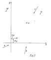
- Figure 1 shows a system comprising three fixed stations, namely a master station SO and two subsidiary stations S1 and S2.
- the station SO is assumed to be at a control centre constituting the origin of a coordinate system used in determining the positions x, y of vehicles typified by one vehicle V.
- Each station is equipped with a receiver of known form, e.g. an Omega receiver, adapted to determine its position.
- a receiver of known form e.g. an Omega receiver
- the fixes are made, as in all hyperbolic systems, on the basis of the signals coming from three transmitters which will be denoted A, B, and C.
- Correspondingly labelled arrows in Figure 1 symbolise the direction of the incoming signals.
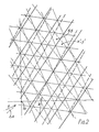
- Figure 2 illustrates the princple underlying hyperbolic systems in general. Only the A and B signals are considered and their wavefronts are shown by light lines normal to the arrows A and B respectively. Over an area a few tens of kilometres across the wavefronts may be assumed to be straight as may the sections of the hyperbolae which are lines of constant phase difference, shown in heavy lines. The spacing between these lines, i.e. the lane width, is determined by the local wavelength ⁇ of the signals.
- the propagation distortions affecting the transmitted signals do not merely affect their absolute phase at any phase. They also affect ⁇ and they alter the angles of the wavefronts.
- AA will usually consist of an unvarying component ⁇ A o and a time varying component AA'.
- the latter component has to be determined by continuous monitoring by application of the present invention but the unvarying component ⁇ A 0 , which arises essentially from the local topography, can be determined and stored in a computer.
- the above equation becomes which can be rewritten
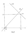
- Figure 3 illustrates the principle upon which the present invention is based.
- the master station is assumed to be correctly located at the origin i.e. the correction according to differential Omega has been applied.
- the line AP represents the propagation direction while the line AW represents a wavefront through S1.
- Equation (5) and (6) we have A second, non-redundant equation may be written for station S1, and a third w signal C, namely Two equations may also be written for station S2, of the same form as equations (8) and (9).
- the terms are the constants calculable from the geodetically known conditions, the nine measured quantities PA 0 , PB 0 , PC o , PA 1 , PB 1 , PC 1 , PA 2 , PB 2 , PC 2 and four unknowns, AA, ⁇ B, ⁇ C and ⁇ .
- the equations are linear simultaneous equations which are readily solvable to determine the four unknowns.
- PA 0 etc. are preferably first corrected to take account of the fixed azimuth errors ⁇ A 0 etc.
- FIG. 4 shows a system embodying the invention.
- the station SO comprises an Omega receiver 10 and a central data processing unit (CPU) 12 provided with a communications interface 14.
- the stations S1 and S2 comprise respective Omega receivers 16 and 18 and interfaces 20 and 22.
- Communication links 24, e.g. landlines or radio communication channels, enable the stations S1 and S2 to transmit their raw data PA 1 ...PC 2 to the CPU 12 which is programmed to solve the equations as explained above.
- the CPU therefore stores the correcting quantities AA, ⁇ B, ⁇ C and ⁇ . In practice, use may be made of more than three of the Omega transmitters and additional correcting quantities ⁇ D, AE... may be calculated and stored.
- the mobile station V also comprises an Omega receiver 26 and interface 28 for a communications link 30 with the station S0.
- This link will be a radio link.
- the way in which use is made of the correcting terms will depend upon the nahure of the fleet of vehicles and where the position information is required. If the information is required at the station S0, e.g. in the case of a fleet of police cars, the link 30 may be used to send the raw Omega data to the station S0.
- the CPU 12 calculates the vehicle position from this data by firstly applying the differential Omega correction in known way and they by correcting A o , B o and C o before applying the Omega calculations to determine x and y for the vehicle.
- the link 30 may be used to transmit phase correcting information in the normal way for differential Omega, the receiver 26 being a conventional differential Omega receiver which transmits data to the station SO already corrected to bring SO to the origin.
- the corrections to take account of AA, ⁇ B, ⁇ C and ⁇ are then made in the CPU 12.
- the corrections AA, AB, AC and ⁇ may be transmitted thereto over the link 30.
- the receiver 26 then has to be adapted to apply these corrections to A o , B o , C o and ⁇ 0 before calculating a fix. Operation in this manner will yield even better accuracy for coastal water navigation. To economise in data link capacity it may be desirable to undertake signal processing before transmission in a CPU at stations S1, S2 and V.
Landscapes
- Physics & Mathematics (AREA)
- Engineering & Computer Science (AREA)
- General Physics & Mathematics (AREA)
- Radar, Positioning & Navigation (AREA)
- Remote Sensing (AREA)
- Position Fixing By Use Of Radio Waves (AREA)
Claims (9)
Applications Claiming Priority (2)
| Application Number | Priority Date | Filing Date | Title |
|---|---|---|---|
| EP83304611 | 1983-08-09 | ||
| EP83304611 | 1983-08-09 |
Publications (2)
| Publication Number | Publication Date |
|---|---|
| EP0133807A1 EP0133807A1 (de) | 1985-03-06 |
| EP0133807B1 true EP0133807B1 (de) | 1989-05-24 |
Family
ID=8191237
Family Applications (1)
| Application Number | Title | Priority Date | Filing Date |
|---|---|---|---|
| EP84305348A Expired EP0133807B1 (de) | 1983-08-09 | 1984-08-07 | Ortsbestimmungssystem |
Country Status (4)
| Country | Link |
|---|---|
| US (1) | US4680590A (de) |
| EP (1) | EP0133807B1 (de) |
| JP (1) | JPS6058566A (de) |
| DE (1) | DE3478348D1 (de) |
Families Citing this family (6)
| Publication number | Priority date | Publication date | Assignee | Title |
|---|---|---|---|---|
| FI78566C (fi) * | 1988-04-26 | 1989-08-10 | Vaisala Oy | Foerfarande och anordning vid antenn- och mottagningssystem av en radioteodolit. |
| US4884208A (en) * | 1988-05-16 | 1989-11-28 | Equipment Tracking Network, Inc. | System for continuously establishing and indicating the location of a movable object |
| US5165302A (en) * | 1988-12-02 | 1992-11-24 | Kabushiki Kaisha Tokai-Rika-Denki-Seisakusho | Steering apparatus with fixed pad |
| GB2241623A (en) * | 1990-02-28 | 1991-09-04 | Philips Electronic Associated | Vehicle location system |
| US5208756A (en) * | 1991-01-28 | 1993-05-04 | Song Han L | Vehicle locating and navigating system |
| US9081078B2 (en) * | 2010-02-02 | 2015-07-14 | Alcatel Lucent | Technique for effectively communicating location information in a wireless communication service |
Family Cites Families (10)
| Publication number | Priority date | Publication date | Assignee | Title |
|---|---|---|---|---|
| GB673050A (en) * | 1950-09-07 | 1952-05-28 | Decca Record Co Ltd | Improvements in or relating to radio range-indicating systems |
| GB765573A (en) * | 1954-03-08 | 1957-01-09 | Decca Record Co Ltd | Improvements in or relating to radio navigation systems |
| US3242494A (en) * | 1962-01-25 | 1966-03-22 | Raytheon Co | Position determination system |
| US3419865A (en) * | 1967-05-10 | 1968-12-31 | John P. Chisholm | Mobile emergency unit locating system |
| DE1934960C3 (de) * | 1969-07-10 | 1979-01-25 | Prakla-Seismos Gmbh, 3000 Hannover | Verfahren und Anordnung zum genauen Orten von Punkten |
| US3774215A (en) * | 1970-11-23 | 1973-11-20 | Gen Systems Dev Corp | Position locating system |
| FR2180549B1 (de) * | 1972-04-20 | 1977-01-14 | Sercel Rech Const Elect | |
| US4232317A (en) * | 1978-11-01 | 1980-11-04 | Freeny Jr Charles C | Quantized hyperbolic and inverse hyperbolic object location system |
| DE2853317A1 (de) * | 1978-12-09 | 1980-06-19 | Licentia Gmbh | Einrichtung zur standortbestimmung von fahrzeugen |
| US4492963A (en) * | 1983-10-05 | 1985-01-08 | Eg&G, Inc. | Method and apparatus for determining lane count error in a radio navigational system |
-
1984
- 1984-08-02 US US06/637,204 patent/US4680590A/en not_active Expired - Lifetime
- 1984-08-07 EP EP84305348A patent/EP0133807B1/de not_active Expired
- 1984-08-07 DE DE8484305348T patent/DE3478348D1/de not_active Expired
- 1984-08-09 JP JP59167264A patent/JPS6058566A/ja active Pending
Also Published As
| Publication number | Publication date |
|---|---|
| JPS6058566A (ja) | 1985-04-04 |
| EP0133807A1 (de) | 1985-03-06 |
| US4680590A (en) | 1987-07-14 |
| DE3478348D1 (en) | 1989-06-29 |
Similar Documents
| Publication | Publication Date | Title |
|---|---|---|
| US4652884A (en) | Satellite navigational system and method | |
| US5099245A (en) | Vehicle location system accuracy enhancement for airborne vehicles | |
| EP0346461B1 (de) | Fahrzeug-ortungssystem mit grösserer genauigkeit für luftfahrzeuge | |
| US6127975A (en) | Single station communications localization system | |
| CA1313560C (en) | Position determination and message transfer system employing satellites and stored terrain map | |
| EP1185878B1 (de) | Verbesserungen in funkortungssystemen | |
| CA1297972C (en) | Landing assistance system using navigation satellites | |
| US5191342A (en) | Fix-tracking system | |
| US5111209A (en) | Satellite-based position determining system | |
| US7646338B2 (en) | Method of optimization of processing of location data in the presence of a plurality of satellite positioning constellations | |
| EP2312331A1 (de) | Verfahren und system zum benutzen eines ausstrahlungs-fm-signals zur positionsbestimmung der geografischen position | |
| US3430234A (en) | Navigation systems using earth satellites | |
| US20020126046A1 (en) | Instantaneous radiopositioning using signals of opportunity | |
| US20040119638A1 (en) | Navigation system using locally augmented GPS | |
| JPS58129277A (ja) | 双曲線方式電波航行装置 | |
| US20080036654A1 (en) | Method for fusing multiple gps measurement types into a weighted least squares solution | |
| CN115426035B (zh) | 一种基于剖分网格的定位初值搜索方法及系统 | |
| KR20240013313A (ko) | 지상파 항법 시스템의 asf 측정 및 예측 시스템과 그 방법 | |
| US4680590A (en) | Position finding system | |
| US5181041A (en) | Accurate location system using transponded and correlated LORAN signals | |
| Swanson et al. | The Omega navigation system | |
| EP1671150B1 (de) | Geographisches und raum-positionierungssystem und prozess | |
| EP3896475A1 (de) | Verbessertes loran-system mit mehreren sendefrequenzen | |
| Tyler et al. | Location and guidance for site‐specific management | |
| JP2000180528A (ja) | 移動体測位方法とその移動体測位システム |
Legal Events
| Date | Code | Title | Description |
|---|---|---|---|
| PUAI | Public reference made under article 153(3) epc to a published international application that has entered the european phase |
Free format text: ORIGINAL CODE: 0009012 |
|
| AK | Designated contracting states |
Designated state(s): DE FR GB NL SE |
|
| 17P | Request for examination filed |
Effective date: 19850326 |
|
| 17Q | First examination report despatched |
Effective date: 19870305 |
|
| GRAA | (expected) grant |
Free format text: ORIGINAL CODE: 0009210 |
|
| AK | Designated contracting states |
Kind code of ref document: B1 Designated state(s): DE FR GB NL SE |
|
| REF | Corresponds to: |
Ref document number: 3478348 Country of ref document: DE Date of ref document: 19890629 |
|
| PGFP | Annual fee paid to national office [announced via postgrant information from national office to epo] |
Ref country code: SE Payment date: 19890630 Year of fee payment: 6 |
|
| ET | Fr: translation filed | ||
| PGFP | Annual fee paid to national office [announced via postgrant information from national office to epo] |
Ref country code: NL Payment date: 19890831 Year of fee payment: 6 |
|
| PGFP | Annual fee paid to national office [announced via postgrant information from national office to epo] |
Ref country code: DE Payment date: 19891031 Year of fee payment: 6 |
|
| PLBE | No opposition filed within time limit |
Free format text: ORIGINAL CODE: 0009261 |
|
| STAA | Information on the status of an ep patent application or granted ep patent |
Free format text: STATUS: NO OPPOSITION FILED WITHIN TIME LIMIT |
|
| 26N | No opposition filed | ||
| PG25 | Lapsed in a contracting state [announced via postgrant information from national office to epo] |
Ref country code: SE Effective date: 19900808 |
|
| PG25 | Lapsed in a contracting state [announced via postgrant information from national office to epo] |
Ref country code: NL Effective date: 19910301 |
|
| NLV4 | Nl: lapsed or anulled due to non-payment of the annual fee | ||
| PG25 | Lapsed in a contracting state [announced via postgrant information from national office to epo] |
Ref country code: DE Effective date: 19910501 |
|
| EUG | Se: european patent has lapsed |
Ref document number: 84305348.9 Effective date: 19910410 |
|
| REG | Reference to a national code |
Ref country code: GB Ref legal event code: IF02 |
|
| PGFP | Annual fee paid to national office [announced via postgrant information from national office to epo] |
Ref country code: GB Payment date: 20030806 Year of fee payment: 20 |
|
| PGFP | Annual fee paid to national office [announced via postgrant information from national office to epo] |
Ref country code: FR Payment date: 20030808 Year of fee payment: 20 |
|
| PG25 | Lapsed in a contracting state [announced via postgrant information from national office to epo] |
Ref country code: GB Free format text: LAPSE BECAUSE OF EXPIRATION OF PROTECTION Effective date: 20040806 |
|
| REG | Reference to a national code |
Ref country code: GB Ref legal event code: PE20 |