EP0133629B1 - A rotary positive displacement machine - Google Patents
A rotary positive displacement machine Download PDFInfo
- Publication number
- EP0133629B1 EP0133629B1 EP83304358A EP83304358A EP0133629B1 EP 0133629 B1 EP0133629 B1 EP 0133629B1 EP 83304358 A EP83304358 A EP 83304358A EP 83304358 A EP83304358 A EP 83304358A EP 0133629 B1 EP0133629 B1 EP 0133629B1
- Authority
- EP
- European Patent Office
- Prior art keywords
- port
- rotor
- arc
- edge
- rotation
- Prior art date
- Legal status (The legal status is an assumption and is not a legal conclusion. Google has not performed a legal analysis and makes no representation as to the accuracy of the status listed.)
- Expired
Links
- 238000006073 displacement reaction Methods 0.000 title claims description 14
- 239000012530 fluid Substances 0.000 claims description 19
- 238000007789 sealing Methods 0.000 claims description 9
- 230000006835 compression Effects 0.000 claims description 3
- 238000007906 compression Methods 0.000 claims description 3
- 230000003405 preventing effect Effects 0.000 claims 1
- 238000003801 milling Methods 0.000 description 4
- 230000015572 biosynthetic process Effects 0.000 description 1
- 238000010276 construction Methods 0.000 description 1
- 238000004519 manufacturing process Methods 0.000 description 1
Images


Classifications
-
- F—MECHANICAL ENGINEERING; LIGHTING; HEATING; WEAPONS; BLASTING
- F01—MACHINES OR ENGINES IN GENERAL; ENGINE PLANTS IN GENERAL; STEAM ENGINES
- F01C—ROTARY-PISTON OR OSCILLATING-PISTON MACHINES OR ENGINES
- F01C1/00—Rotary-piston machines or engines
- F01C1/08—Rotary-piston machines or engines of intermeshing engagement type, i.e. with engagement of co- operating members similar to that of toothed gearing
- F01C1/12—Rotary-piston machines or engines of intermeshing engagement type, i.e. with engagement of co- operating members similar to that of toothed gearing of other than internal-axis type
- F01C1/123—Rotary-piston machines or engines of intermeshing engagement type, i.e. with engagement of co- operating members similar to that of toothed gearing of other than internal-axis type with tooth-like elements, extending generally radially from the rotor body cooperating with recesses in the other rotor, e.g. one tooth
Definitions
- This invention pertains to rotary, positive displacement machines for handling a working fluid, such as gas and, in particular, to such machines as are useful as gas compressors or gas expanders, or the like.
- US-A-3,472,445 appears to have set forth the first teaching of the optimum location and definition or configuration of the high-pressure port in the end wall (or walls) of a rotary displacement machine such as a gas compressor.
- This teaching is of defining the port with an arcuate edge which conforms and aligns, axially, with the outermost reach or tip of the main rotor tooth.
- GB-A-1,304,394 discloses a rotary, positive displacement machine having two rotors mounted in respective bores, each rotor having a hub and a lobe integral with the hub. One of the discharge rotors occludes a discharge port for some of the time, the discharge port being substantially fully opened during rotation of one of the rotors and being closed off as close to a plane joining the axes of the rotors as possible. In GB-A-1,304,394, to carry the discharge port beyond said plane would open the discharge port to the low-pressure side of the machine, which would be self-defeating.
- a rotary, positive displacement machine adapted to handle a working fluid, comprising a casing structure having two intersecting bores and end walls; a first rotor mounted for rotation in one said bore; and a second rotor mounted for rotation in the other said bore said rotors being mounted on parallel axes on a common plane; wherein each rotor has a hub and at least one lobe; each lobe is integral with a respective hub and projects generally radially outward therefrom, defining an outermost radial surface of the rotor; each hub has formed therein at least one groove; defining an innermost radial surface of the rotor, to receive, interengagingly therein, one of said lobes; said hubs are configured so as to rotate in substantially sealing relation to each other during at least a portion of each rotation; said casing structure has a first port for the passage therethrough of the working fluid at a given pressure, and a second port for the passage therethrough of the working fluid at higher
- the minor wall portion of the second port is traversed by the common plane.
- the prior art rotary, positive displacement machines 10 have an end wall exhaust port 12 which terminates at approximately twenty degrees of arc from the plane 14 in which both the gating rotor 16 and the main rotor 18 are journalled. Simply, the twenty-degree termination is necessary due to the fact that the milling machine cannot define a smaller-radius- sed, narrower cut. Hence, a pocket "A" of product, compressed gas can not be delivered and must be dumped back to the inlet side of the machine.
- an exhaust port 12' would extend to, and terminate at, the plane 14 in which the rotors are journalled, as shown in Figure 2, but there is no practical way to cut such a thin, tapering and disappearing extension 20 with customary milling machines or the like. Too, to define such a cut with other machinery or hand tools is prohibitively time-consuming and expensive.
- the end wall exhaust port 12 has a radially outermost edge 22 which obtains at a slightly shorter radial distance than does the arc defined by the hub 24 of the gating rotor 16. This is to ensure that during the compression cycle the exhaust port 12 will be occluded by the gating rotor hub 24. During the delivery cycle, the exhaust port 12 must be fully exposed and, as a consequence, the innermost edge 26 of the port is drawn on an arc which axially aligns with the arc of the groove 28 of the gating rotor 16.
- the outermost and the innermost edges are joined by an arcuate edge describing a radial arc substantially common with the outermost radial surface of the main rotor 18.
- the innermost edge 26 of the exhaust port 12 should not extend, radially, further than the groove 28 of the gating rotor, as this would occlude some of the port and cause undue throttling thereat.
- to have the edge 26 foreshortened, to underlie the groove 28, would be counter-productive as the underlying portion would serve no function; such underlying portion would not contribute to the effective area of the port, and it would simply be inoperatively occluded by the rotor 16.
- Such is the plausible thinking in this art and, accordingly, sensibly, machines of this type have the innermost edge 26 of the high-pressure port 26 fully axially aligned with the edge of the groove 28 (which is to fully expose the port).
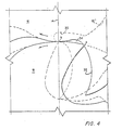
- Figures 3 and 4 show, in full line illustration, the disposition of the rotors 16 and 18 prior to the final or terminal delivery of the product gas.
- the invention as defined in claim 1 gives rise to the formation of an extension, for the end wall exhaust port 12", having a width which can be cut by a conventional milling machine, the innermost edge of the extension being concentric and parallel to the arcuate edge of the second port, and consequently beyond the rotary sweep of the second rotor.
- the rotors 16 and 18 define sealing lines "a" and "b", the latter always occurring on the plane 14. Now, when the sealing lines coincide, the rotors are in the dashed-line positionings shown ( Figures 3 and 4). At such time, the concave flank 32 of the gating rotor 16 is just concluding a closure of the smallest portion of the extension.. Immediately thereafter, the extension is fully occluded. However, while the rotors travel from the full-line positioning to the dashed-line positioning, the extension 30 provides an access 34 for the last portion of product gas to be delivered into the end wall exhaust port 12".
Landscapes
- Engineering & Computer Science (AREA)
- Mechanical Engineering (AREA)
- General Engineering & Computer Science (AREA)
- Applications Or Details Of Rotary Compressors (AREA)
- Rotary Pumps (AREA)
Description
- This invention pertains to rotary, positive displacement machines for handling a working fluid, such as gas and, in particular, to such machines as are useful as gas compressors or gas expanders, or the like.
- Machines of the type to which the invention pertains are rather well known in the prior art, particularly from US-A-3,535,060; 3,472,445 and 4,224,016, and CA-A-965,354.
- US-A-3,472,445 appears to have set forth the first teaching of the optimum location and definition or configuration of the high-pressure port in the end wall (or walls) of a rotary displacement machine such as a gas compressor. This teaching is of defining the port with an arcuate edge which conforms and aligns, axially, with the outermost reach or tip of the main rotor tooth. Thus, as the high-pressure port is closed over, by the interengagement of the coacting rotor teeth and grooves, substantially all of the product gas will be delivered, therethrough (in a gas compressorfunc- tion, wherein the port is an exhaust port).
- In US-A-3,535,060, column 5, lines 73 through h 75, the point is made that the end wall exhaust port should have an optimum shape and area. More pointedly, in the CA-A-965,354 it is suggested, with some want of clarity, that the end wall exhaust port should extend to (a) within approximately twenty degrees of the common plane in which the rotors are journal led, and (b) to the plane whereat sealing lines between the rotors coincide. Well, extension to about twenty degrees of the common plane of rotor journalling appears to be disclosed in the prior art (including US-A-3,472,445), and extension to the plane whereat the sealing lines coincide is not "... approximately 20 degrees about the axis of rotation ..." of the gating rotor from the common plane. Rather, the sealing lines coincide on said common plane. If the Canadian patent disclosure is ambiguous, and if the US-A-3,472,445 disclosed only a desired feature, it is a fact of manufacturing reality that it has not been possible to define the exhaust port with a sufficient extension. Accordingly, there has always been a minor portion of the compressed- gas product which is not deliverable and must be dumped back to the inlet.
- GB-A-1,304,394 discloses a rotary, positive displacement machine having two rotors mounted in respective bores, each rotor having a hub and a lobe integral with the hub. One of the discharge rotors occludes a discharge port for some of the time, the discharge port being substantially fully opened during rotation of one of the rotors and being closed off as close to a plane joining the axes of the rotors as possible. In GB-A-1,304,394, to carry the discharge port beyond said plane would open the discharge port to the low-pressure side of the machine, which would be self-defeating.
- It is an object of this invention to disclose a rotary positive displacement machine having an end wall exhaust port with an extension which, in use of the machine as a gas compressor, will ensure the delivery of all the product gas (except for gas lost internally in the machine).
- According to the present invention, there is provided a rotary, positive displacement machine adapted to handle a working fluid, comprising a casing structure having two intersecting bores and end walls; a first rotor mounted for rotation in one said bore; and a second rotor mounted for rotation in the other said bore said rotors being mounted on parallel axes on a common plane; wherein each rotor has a hub and at least one lobe; each lobe is integral with a respective hub and projects generally radially outward therefrom, defining an outermost radial surface of the rotor; each hub has formed therein at least one groove; defining an innermost radial surface of the rotor, to receive, interengagingly therein, one of said lobes; said hubs are configured so as to rotate in substantially sealing relation to each other during at least a portion of each rotation; said casing structure has a first port for the passage therethrough of the working fluid at a given pressure, and a second port for the passage therethrough of the working fluid at higher pressure than said given pressure; at least a portion of said second port is located in an end wall of the bore containing said first rotor, and has a radially innermost edge, a radially outermost edge, and an arcuate edge joining said innermost and outermost edges; said hub of the first rotor and its groove therein comprise means for cyclically covering and uncovering said second port so as to control the flow of the higher-pressure working fluid through said second port; said rotors are adapted to displace the working fluid inside said bores; said machine has a built-in compression ratio, when operating as a fluid compressor, such that the working fluid is compressed internally within the machine before passing through said second port, and a built-in expansion ratio, when operating as a fluid expander, such that the working fluid expands internally within the machine before passing through said first port; said outermost radial surface of said second rotor, during rotation of the latter, and said arcuate edge of said port, describe a first, substantially common, radial arc; and said radially innermost edge of said second port has a major portion thereof which, with rotor rotation, comes into substantially axial alignment with said groove in said first rotor, said major portion of said radially innermost edge of said second port describing a second arc, drawn from the radial centre of said first rotor, which second arc is substantially the same as an arc described, during rotation thereof, by said innermost radial surface of said first rotor; characterized in that said radially innermost edge of said second port has a minor portion thereof which is radially inward relative to said second arc and is constantly occluded by said first rotor, and said minor portion and said arcuate edge being concentric.
- Preferably, the minor wall portion of the second port is traversed by the common plane.
- For a better understanding of the invention and to show how the same may be carried into effect, reference will now be made, by way of example, to the accompanying drawings, in which:-
- Figure 1 is a detailed illustration of a typical, end wall exhaust port, shown cross-hatched for contrast only, in a rotary positive displacement machine according to the prior art;
- Figure 2 is a depiction of an idealised or theoretical, end wall exhaust port, also shown cross-hatched for contrast, for such machines as aforesaid;
- Figure 3 is an illustration of the present rotary, positive displacement machine; and
- Figure 4 is an enlarged, detailed view of part of the construction shown in Figure 3.
- Referring to Figures 1 and 2, the prior art rotary,
positive displacement machines 10 have an endwall exhaust port 12 which terminates at approximately twenty degrees of arc from theplane 14 in which both thegating rotor 16 and themain rotor 18 are journalled. Simply, the twenty-degree termination is necessary due to the fact that the milling machine cannot define a smaller-radius- sed, narrower cut. Hence, a pocket "A" of product, compressed gas can not be delivered and must be dumped back to the inlet side of the machine. Ideally, an exhaust port 12' would extend to, and terminate at, theplane 14 in which the rotors are journalled, as shown in Figure 2, but there is no practical way to cut such a thin, tapering and disappearingextension 20 with customary milling machines or the like. Too, to define such a cut with other machinery or hand tools is prohibitively time-consuming and expensive. - As set forth in the prior art, and notably the patents discussed above, the end
wall exhaust port 12 has a radiallyoutermost edge 22 which obtains at a slightly shorter radial distance than does the arc defined by thehub 24 of thegating rotor 16. This is to ensure that during the compression cycle theexhaust port 12 will be occluded by thegating rotor hub 24. During the delivery cycle, theexhaust port 12 must be fully exposed and, as a consequence, theinnermost edge 26 of the port is drawn on an arc which axially aligns with the arc of thegroove 28 of thegating rotor 16. The outermost and the innermost edges are joined by an arcuate edge describing a radial arc substantially common with the outermost radial surface of themain rotor 18. Theinnermost edge 26 of theexhaust port 12 should not extend, radially, further than thegroove 28 of the gating rotor, as this would occlude some of the port and cause undue throttling thereat. Conversely, to have theedge 26 foreshortened, to underlie thegroove 28, would be counter-productive as the underlying portion would serve no function; such underlying portion would not contribute to the effective area of the port, and it would simply be inoperatively occluded by therotor 16. Such is the plausible thinking in this art and, accordingly, sensibly, machines of this type have theinnermost edge 26 of the high-pressure port 26 fully axially aligned with the edge of the groove 28 (which is to fully expose the port). - It is the teaching of the present invention, however, to proceed counter to this prior art thinking, and deliberately define a portion of the exhaust port to underlie the gating rotor so that it is constantly occluded by the gating rotor. Further, it is the teaching of the present invention to define the exhaust or high-pressure port with an extension which is traversed by the plane in which the rotors are journalled. This is to ensure that, during the delivery cycle, the port is opened fully to that plane, that plane being the same in which the sealing lines coincide. Following the delivery cycle, the
gating rotor 16 closes off the entire port extension, so that the extension is not, then, exposed to the inlet side of the machine. - Figures 3 and 4 show, in full line illustration, the disposition of the
rotors wall exhaust port 12", having a width which can be cut by a conventional milling machine, the innermost edge of the extension being concentric and parallel to the arcuate edge of the second port, and consequently beyond the rotary sweep of the second rotor. - It will be seen that, while a substantial portion of the exhaust port extension is occluded by the
gating rotor 16, a minor portion thereof can remain open fully to theplane 14 whereat therotors - The
rotors plane 14. Now, when the sealing lines coincide, the rotors are in the dashed-line positionings shown (Figures 3 and 4). At such time, theconcave flank 32 of thegating rotor 16 is just concluding a closure of the smallest portion of the extension.. Immediately thereafter, the extension is fully occluded. However, while the rotors travel from the full-line positioning to the dashed-line positioning, theextension 30 provides anaccess 34 for the last portion of product gas to be delivered into the endwall exhaust port 12". - By milling a greater exhaust port extension than can be useful, a minor portion thereof is defined which is not only functional, but comprises the means for ensuring delivery of all possible product gas.
Claims (5)
Priority Applications (2)
| Application Number | Priority Date | Filing Date | Title |
|---|---|---|---|
| DE8383304358T DE3376276D1 (en) | 1983-07-27 | 1983-07-27 | A rotary positive displacement machine |
| AT83304358T ATE33515T1 (en) | 1983-07-27 | 1983-07-27 | ROTARY PISTON DISPLACEMENT MACHINE. |
Applications Claiming Priority (1)
| Application Number | Priority Date | Filing Date | Title |
|---|---|---|---|
| US06/222,050 US4406601A (en) | 1981-01-02 | 1981-01-02 | Rotary positive displacement machine |
Publications (2)
| Publication Number | Publication Date |
|---|---|
| EP0133629A1 EP0133629A1 (en) | 1985-03-06 |
| EP0133629B1 true EP0133629B1 (en) | 1988-04-13 |
Family
ID=22830577
Family Applications (1)
| Application Number | Title | Priority Date | Filing Date |
|---|---|---|---|
| EP83304358A Expired EP0133629B1 (en) | 1981-01-02 | 1983-07-27 | A rotary positive displacement machine |
Country Status (3)
| Country | Link |
|---|---|
| US (1) | US4406601A (en) |
| EP (1) | EP0133629B1 (en) |
| AU (1) | AU563204B2 (en) |
Families Citing this family (14)
| Publication number | Priority date | Publication date | Assignee | Title |
|---|---|---|---|---|
| US4556324A (en) * | 1984-05-01 | 1985-12-03 | E. I. Du Pont De Nemours And Company | Apparatus for forming films of constant thickness |
| GB2243651A (en) * | 1990-05-05 | 1991-11-06 | Drum Eng Co Ltd | Rotary, positive displacement machine |
| RS50951B (en) * | 2001-02-23 | 2010-08-31 | Ateliers Busch Sa. | COMPRESSIBLE MEDIA PISTON MACHINE |
| US6776594B1 (en) * | 2003-06-02 | 2004-08-17 | Liung Feng Industrial Co., Ltd. | Rotor mechanism |
| CN1904365B (en) * | 2005-07-29 | 2010-06-16 | 良峰塑胶机械股份有限公司 | Claw type rotor design method |
| RU2282063C1 (en) * | 2005-09-01 | 2006-08-20 | Виктор Павлович Шлапацкий | Rotary machine |
| CN100526607C (en) * | 2005-12-23 | 2009-08-12 | 良峰塑胶机械股份有限公司 | Blade design method of claw type rotor |
| CN100526609C (en) * | 2005-12-30 | 2009-08-12 | 良峰塑胶机械股份有限公司 | Single-claw and double-claw design method of claw type rotor |
| CN100526608C (en) * | 2006-01-05 | 2009-08-12 | 良峰塑胶机械股份有限公司 | Three-jaw and more than three-jaw design method of jaw type rotor |
| CN100526610C (en) * | 2006-01-05 | 2009-08-12 | 良峰塑胶机械股份有限公司 | Single-claw design method of claw type rotor |
| EP2088284A1 (en) | 2008-02-11 | 2009-08-12 | Liung Feng Industrial Co Ltd | Method for designing lobe-type rotors |
| WO2012051710A1 (en) | 2010-10-22 | 2012-04-26 | Peter South | Rotary positive displacement machine |
| JP5725660B2 (en) | 2011-09-30 | 2015-05-27 | アネスト岩田株式会社 | Claw pump |
| CN103775341B (en) | 2012-10-15 | 2016-05-18 | 良峰塑胶机械股份有限公司 | Two jaw-type rotor pairs with the same shape |
Citations (3)
| Publication number | Priority date | Publication date | Assignee | Title |
|---|---|---|---|---|
| US3472445A (en) * | 1968-04-08 | 1969-10-14 | Arthur E Brown | Rotary positive displacement machines |
| US3535060A (en) * | 1969-03-21 | 1970-10-20 | Arthur E Brown | Rotary displacement machines |
| GB1304394A (en) * | 1969-04-29 | 1973-01-24 |
Family Cites Families (7)
| Publication number | Priority date | Publication date | Assignee | Title |
|---|---|---|---|---|
| SE399946B (en) * | 1969-06-18 | 1978-03-06 | Atlas Copco Ab | ROTOR MACHINE WITH A MAIN ROTOR AND A SLIDING ROTOR |
| US3894822A (en) * | 1974-04-22 | 1975-07-15 | Alfred Ibragimovich Abaidullin | Interengaging rotor displacement machine |
| US3989413A (en) * | 1975-05-14 | 1976-11-02 | Ingersoll-Rand Company | Gas compressor unloading means |
| US4138848A (en) * | 1976-12-27 | 1979-02-13 | Bates Kenneth C | Compressor-expander apparatus |
| US4224016A (en) * | 1978-09-27 | 1980-09-23 | Brown Arthur E | Rotary positive displacement machines |
| US4324538A (en) * | 1978-09-27 | 1982-04-13 | Ingersoll-Rand Company | Rotary positive displacement machine with specific lobed rotor profiles |
| ZA794573B (en) * | 1978-09-28 | 1980-08-27 | A Brown | Rotary positive displacement machines |
-
1981
- 1981-01-02 US US06/222,050 patent/US4406601A/en not_active Expired - Fee Related
-
1983
- 1983-07-27 EP EP83304358A patent/EP0133629B1/en not_active Expired
- 1983-08-04 AU AU17594/83A patent/AU563204B2/en not_active Ceased
Patent Citations (3)
| Publication number | Priority date | Publication date | Assignee | Title |
|---|---|---|---|---|
| US3472445A (en) * | 1968-04-08 | 1969-10-14 | Arthur E Brown | Rotary positive displacement machines |
| US3535060A (en) * | 1969-03-21 | 1970-10-20 | Arthur E Brown | Rotary displacement machines |
| GB1304394A (en) * | 1969-04-29 | 1973-01-24 |
Also Published As
| Publication number | Publication date |
|---|---|
| AU563204B2 (en) | 1987-07-02 |
| US4406601A (en) | 1983-09-27 |
| EP0133629A1 (en) | 1985-03-06 |
| AU1759483A (en) | 1985-02-07 |
Similar Documents
| Publication | Publication Date | Title |
|---|---|---|
| US4406601A (en) | Rotary positive displacement machine | |
| US4412796A (en) | Helical screw rotor profiles | |
| US3472445A (en) | Rotary positive displacement machines | |
| US5149256A (en) | Rotary, positive displacement machine with specific lobed rotor profile | |
| US4508496A (en) | Rotary, positive-displacement machine, of the helical-rotor type, and rotors therefor | |
| EP0009916B1 (en) | Rotary positive displacement machines | |
| JPH0456155B2 (en) | ||
| EP0421499B1 (en) | Rotary fluid machine | |
| US4430050A (en) | Rotary, positive-displacement machine | |
| KR970001456B1 (en) | Scroll type machine | |
| US7520738B2 (en) | Closed system rotary machine | |
| JPH0320481Y2 (en) | ||
| JPH0311101A (en) | Scroll fluid machine | |
| US4981424A (en) | High pressure single screw compressors | |
| CA1246510A (en) | Rotary positive displacement machine | |
| JPH0565681B2 (en) | ||
| JPS6344956B2 (en) | ||
| JPS63230979A (en) | Vane type compressor | |
| US7163387B2 (en) | Meshing helical rotors | |
| US3072316A (en) | Rotary pump or expansion engine | |
| WO1993017223A1 (en) | Screw rotors type machine | |
| US4312629A (en) | Universal rotating machine for expanding or compressing a compressible fluid | |
| JPH0347495A (en) | Screw-type fluid machine | |
| JP2002021791A (en) | Turbo compressor | |
| JPH0367085A (en) | Contactless pump with single vane |
Legal Events
| Date | Code | Title | Description |
|---|---|---|---|
| PUAI | Public reference made under article 153(3) epc to a published international application that has entered the european phase |
Free format text: ORIGINAL CODE: 0009012 |
|
| AK | Designated contracting states |
Designated state(s): AT BE CH DE FR GB IT LI LU NL SE |
|
| 17P | Request for examination filed |
Effective date: 19850614 |
|
| ITF | It: translation for a ep patent filed | ||
| GRAA | (expected) grant |
Free format text: ORIGINAL CODE: 0009210 |
|
| AK | Designated contracting states |
Kind code of ref document: B1 Designated state(s): AT BE CH DE FR GB IT LI LU NL SE |
|
| REF | Corresponds to: |
Ref document number: 33515 Country of ref document: AT Date of ref document: 19880415 Kind code of ref document: T |
|
| REF | Corresponds to: |
Ref document number: 3376276 Country of ref document: DE Date of ref document: 19880519 |
|
| ET | Fr: translation filed | ||
| PLBE | No opposition filed within time limit |
Free format text: ORIGINAL CODE: 0009261 |
|
| STAA | Information on the status of an ep patent application or granted ep patent |
Free format text: STATUS: NO OPPOSITION FILED WITHIN TIME LIMIT |
|
| 26N | No opposition filed | ||
| ITTA | It: last paid annual fee | ||
| PGFP | Annual fee paid to national office [announced via postgrant information from national office to epo] |
Ref country code: FR Payment date: 19930610 Year of fee payment: 11 |
|
| PGFP | Annual fee paid to national office [announced via postgrant information from national office to epo] |
Ref country code: CH Payment date: 19930614 Year of fee payment: 11 |
|
| PGFP | Annual fee paid to national office [announced via postgrant information from national office to epo] |
Ref country code: AT Payment date: 19930617 Year of fee payment: 11 |
|
| PGFP | Annual fee paid to national office [announced via postgrant information from national office to epo] |
Ref country code: LU Payment date: 19930618 Year of fee payment: 11 Ref country code: DE Payment date: 19930618 Year of fee payment: 11 |
|
| PGFP | Annual fee paid to national office [announced via postgrant information from national office to epo] |
Ref country code: SE Payment date: 19930621 Year of fee payment: 11 |
|
| PGFP | Annual fee paid to national office [announced via postgrant information from national office to epo] |
Ref country code: GB Payment date: 19930624 Year of fee payment: 11 |
|
| PGFP | Annual fee paid to national office [announced via postgrant information from national office to epo] |
Ref country code: BE Payment date: 19930629 Year of fee payment: 11 |
|
| PGFP | Annual fee paid to national office [announced via postgrant information from national office to epo] |
Ref country code: NL Payment date: 19930731 Year of fee payment: 11 |
|
| EPTA | Lu: last paid annual fee | ||
| PG25 | Lapsed in a contracting state [announced via postgrant information from national office to epo] |
Ref country code: LU Free format text: LAPSE BECAUSE OF NON-PAYMENT OF DUE FEES Effective date: 19940727 Ref country code: GB Effective date: 19940727 Ref country code: AT Effective date: 19940727 |
|
| PG25 | Lapsed in a contracting state [announced via postgrant information from national office to epo] |
Ref country code: SE Effective date: 19940728 |
|
| PG25 | Lapsed in a contracting state [announced via postgrant information from national office to epo] |
Ref country code: LI Effective date: 19940731 Ref country code: CH Effective date: 19940731 Ref country code: BE Effective date: 19940731 |
|
| BERE | Be: lapsed |
Owner name: INGERSOLL-RAND CY Effective date: 19940731 |
|
| EUG | Se: european patent has lapsed |
Ref document number: 83304358.1 Effective date: 19950210 |
|
| PG25 | Lapsed in a contracting state [announced via postgrant information from national office to epo] |
Ref country code: NL Effective date: 19950201 |
|
| NLV4 | Nl: lapsed or anulled due to non-payment of the annual fee | ||
| GBPC | Gb: european patent ceased through non-payment of renewal fee |
Effective date: 19940727 |
|
| PG25 | Lapsed in a contracting state [announced via postgrant information from national office to epo] |
Ref country code: FR Effective date: 19950331 |
|
| REG | Reference to a national code |
Ref country code: CH Ref legal event code: PL |
|
| PG25 | Lapsed in a contracting state [announced via postgrant information from national office to epo] |
Ref country code: DE Effective date: 19950401 |
|
| EUG | Se: european patent has lapsed |
Ref document number: 83304358.1 |
|
| REG | Reference to a national code |
Ref country code: FR Ref legal event code: ST |