JP5725660B2 - Claw pump - Google Patents
Claw pump Download PDFInfo
- Publication number
- JP5725660B2 JP5725660B2 JP2011216393A JP2011216393A JP5725660B2 JP 5725660 B2 JP5725660 B2 JP 5725660B2 JP 2011216393 A JP2011216393 A JP 2011216393A JP 2011216393 A JP2011216393 A JP 2011216393A JP 5725660 B2 JP5725660 B2 JP 5725660B2
- Authority
- JP
- Japan
- Prior art keywords
- rotor
- compression pocket
- discharge port
- claw
- recess
- Prior art date
- Legal status (The legal status is an assumption and is not a legal conclusion. Google has not performed a legal analysis and makes no representation as to the accuracy of the status listed.)
- Expired - Fee Related
Links
Images


Classifications
-
- F—MECHANICAL ENGINEERING; LIGHTING; HEATING; WEAPONS; BLASTING
- F04—POSITIVE - DISPLACEMENT MACHINES FOR LIQUIDS; PUMPS FOR LIQUIDS OR ELASTIC FLUIDS
- F04C—ROTARY-PISTON, OR OSCILLATING-PISTON, POSITIVE-DISPLACEMENT MACHINES FOR LIQUIDS; ROTARY-PISTON, OR OSCILLATING-PISTON, POSITIVE-DISPLACEMENT PUMPS
- F04C18/00—Rotary-piston pumps specially adapted for elastic fluids
- F04C18/08—Rotary-piston pumps specially adapted for elastic fluids of intermeshing-engagement type, i.e. with engagement of co-operating members similar to that of toothed gearing
-
- F—MECHANICAL ENGINEERING; LIGHTING; HEATING; WEAPONS; BLASTING
- F04—POSITIVE - DISPLACEMENT MACHINES FOR LIQUIDS; PUMPS FOR LIQUIDS OR ELASTIC FLUIDS
- F04C—ROTARY-PISTON, OR OSCILLATING-PISTON, POSITIVE-DISPLACEMENT MACHINES FOR LIQUIDS; ROTARY-PISTON, OR OSCILLATING-PISTON, POSITIVE-DISPLACEMENT PUMPS
- F04C25/00—Adaptations of pumps for special use of pumps for elastic fluids
- F04C25/02—Adaptations of pumps for special use of pumps for elastic fluids for producing high vacuum
-
- F—MECHANICAL ENGINEERING; LIGHTING; HEATING; WEAPONS; BLASTING
- F01—MACHINES OR ENGINES IN GENERAL; ENGINE PLANTS IN GENERAL; STEAM ENGINES
- F01C—ROTARY-PISTON OR OSCILLATING-PISTON MACHINES OR ENGINES
- F01C21/00—Component parts, details or accessories not provided for in groups F01C1/00 - F01C20/00
- F01C21/08—Rotary pistons
-
- F—MECHANICAL ENGINEERING; LIGHTING; HEATING; WEAPONS; BLASTING
- F01—MACHINES OR ENGINES IN GENERAL; ENGINE PLANTS IN GENERAL; STEAM ENGINES
- F01C—ROTARY-PISTON OR OSCILLATING-PISTON MACHINES OR ENGINES
- F01C21/00—Component parts, details or accessories not provided for in groups F01C1/00 - F01C20/00
- F01C21/10—Outer members for co-operation with rotary pistons; Casings
- F01C21/104—Stators; Members defining the outer boundaries of the working chamber
- F01C21/108—Stators; Members defining the outer boundaries of the working chamber with an axial surface, e.g. side plates
-
- F—MECHANICAL ENGINEERING; LIGHTING; HEATING; WEAPONS; BLASTING
- F04—POSITIVE - DISPLACEMENT MACHINES FOR LIQUIDS; PUMPS FOR LIQUIDS OR ELASTIC FLUIDS
- F04C—ROTARY-PISTON, OR OSCILLATING-PISTON, POSITIVE-DISPLACEMENT MACHINES FOR LIQUIDS; ROTARY-PISTON, OR OSCILLATING-PISTON, POSITIVE-DISPLACEMENT PUMPS
- F04C18/00—Rotary-piston pumps specially adapted for elastic fluids
- F04C18/08—Rotary-piston pumps specially adapted for elastic fluids of intermeshing-engagement type, i.e. with engagement of co-operating members similar to that of toothed gearing
- F04C18/082—Details specially related to intermeshing engagement type pumps
- F04C18/086—Carter
-
- F—MECHANICAL ENGINEERING; LIGHTING; HEATING; WEAPONS; BLASTING
- F04—POSITIVE - DISPLACEMENT MACHINES FOR LIQUIDS; PUMPS FOR LIQUIDS OR ELASTIC FLUIDS
- F04C—ROTARY-PISTON, OR OSCILLATING-PISTON, POSITIVE-DISPLACEMENT MACHINES FOR LIQUIDS; ROTARY-PISTON, OR OSCILLATING-PISTON, POSITIVE-DISPLACEMENT PUMPS
- F04C18/00—Rotary-piston pumps specially adapted for elastic fluids
- F04C18/08—Rotary-piston pumps specially adapted for elastic fluids of intermeshing-engagement type, i.e. with engagement of co-operating members similar to that of toothed gearing
- F04C18/12—Rotary-piston pumps specially adapted for elastic fluids of intermeshing-engagement type, i.e. with engagement of co-operating members similar to that of toothed gearing of other than internal-axis type
- F04C18/123—Rotary-piston pumps specially adapted for elastic fluids of intermeshing-engagement type, i.e. with engagement of co-operating members similar to that of toothed gearing of other than internal-axis type with radially or approximately radially from the rotor body extending tooth-like elements, co-operating with recesses in the other rotor, e.g. one tooth
-
- F—MECHANICAL ENGINEERING; LIGHTING; HEATING; WEAPONS; BLASTING
- F04—POSITIVE - DISPLACEMENT MACHINES FOR LIQUIDS; PUMPS FOR LIQUIDS OR ELASTIC FLUIDS
- F04C—ROTARY-PISTON, OR OSCILLATING-PISTON, POSITIVE-DISPLACEMENT MACHINES FOR LIQUIDS; ROTARY-PISTON, OR OSCILLATING-PISTON, POSITIVE-DISPLACEMENT PUMPS
- F04C2270/00—Control; Monitoring or safety arrangements
- F04C2270/12—Vibration
-
- F—MECHANICAL ENGINEERING; LIGHTING; HEATING; WEAPONS; BLASTING
- F04—POSITIVE - DISPLACEMENT MACHINES FOR LIQUIDS; PUMPS FOR LIQUIDS OR ELASTIC FLUIDS
- F04C—ROTARY-PISTON, OR OSCILLATING-PISTON, POSITIVE-DISPLACEMENT MACHINES FOR LIQUIDS; ROTARY-PISTON, OR OSCILLATING-PISTON, POSITIVE-DISPLACEMENT PUMPS
- F04C29/00—Component parts, details or accessories of pumps or pumping installations, not provided for in groups F04C18/00 - F04C28/00
- F04C29/0021—Systems for the equilibration of forces acting on the pump
- F04C29/0035—Equalization of pressure pulses
-
- F—MECHANICAL ENGINEERING; LIGHTING; HEATING; WEAPONS; BLASTING
- F04—POSITIVE - DISPLACEMENT MACHINES FOR LIQUIDS; PUMPS FOR LIQUIDS OR ELASTIC FLUIDS
- F04C—ROTARY-PISTON, OR OSCILLATING-PISTON, POSITIVE-DISPLACEMENT MACHINES FOR LIQUIDS; ROTARY-PISTON, OR OSCILLATING-PISTON, POSITIVE-DISPLACEMENT PUMPS
- F04C29/00—Component parts, details or accessories of pumps or pumping installations, not provided for in groups F04C18/00 - F04C28/00
- F04C29/06—Silencing
Description
本発明は、鉤状の爪部を有する2つのロータを備えたクローポンプに関し、詳しくは、圧縮工程の最後に形成される過圧縮ポケットによる動力損失や脈動を抑制又はなくすようにしたクローポンプに関する。 The present invention relates to a claw pump having two rotors having hook-shaped claw portions, and more particularly, to a claw pump that suppresses or eliminates power loss and pulsation due to an over-compression pocket formed at the end of a compression process. .
クローポンプは、ポンプ室を形成するハウジング内で、二つの爪型ロータが、非常に狭いクリアランスを保ったまま非接触で反対方向に回転する。二つの爪型ロータで圧縮ポケットを形成し、この圧縮ポケットで圧縮した圧縮気体を吐出口から吐出する。潤滑油や封液を使わずに連続して吸引、圧縮、及び排気を行う事で、真空状態又は加圧空気を作り出す。このように、潤滑油等の液体を使用しないので、クリーンな排気、吐出を可能とする。また、圧縮工程のないルーツポンプより高い圧縮比を実現できると共に、非接触回転であるので、回転数を制御する事で、省エネ効果の有る、必要に応じた排気を容易に実現できる等の長所をもつ。 In a claw pump, two claw-type rotors rotate in opposite directions in a non-contact manner while maintaining a very narrow clearance in a housing forming a pump chamber. A compression pocket is formed by the two claw-shaped rotors, and compressed gas compressed by the compression pocket is discharged from the discharge port. Vacuum or pressurized air is created by continuous suction, compression, and exhaust without using lubricating oil or sealant. Thus, since liquid such as lubricating oil is not used, clean exhaust and discharge are possible. In addition, it can achieve a higher compression ratio than a roots pump without a compression process, and it is non-contact rotation, so controlling the number of rotations has an energy saving effect and can easily achieve exhaust as needed. It has.
特許文献1には、かかるクローポンプの構成が開示されている。また、本発明者等は、先に、クローポンプを用い、脈動や動力変動を抑制できる多段真空ポンプを提案している(特許文献2)。 Patent Document 1 discloses the configuration of such a claw pump. The present inventors have previously proposed a multistage vacuum pump that can suppress pulsation and power fluctuation using a claw pump (Patent Document 2).
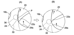
図8に従来の真空用クローポンプの構成を説明する。図8において、クローポンプ100のポンプ室102は、内面が2つの円の一部を重ね合わせた断面形状をした外周壁104と、外周壁104に対し2列に並列に配置された前後サイド壁106とからなる。なお、前方サイド壁の図示は省略されている。ポンプ室102に2本の回転軸108a及び108bが、互いに平行な状態で貫通配置されている。回転軸108aに、半径方向に突出した2個の爪部112a及び112bを備えた雄ロータ110が取り付けられている。一方、回転軸108bに、爪部112a、112bが侵入する凹部116a及び116bを有する雌ロータ114が取り付けられている。
FIG. 8 illustrates the configuration of a conventional vacuum claw pump. In FIG. 8, the
回転軸108a及び108bの軸線を含む平面Lに対して、一方側に吸入口118が設けられ、他方側に吐出口120が設けられている。一対のロータ間、及びロータとポンプ室102の壁面間には微小なクリアランスが設けられている。このクリアランスが大きすぎると、ポンプ室の逆流が起こり、効率が低下する。平面Lより吐出口側に、一対のロータ110、114及び外周壁104、サイド壁106によって囲まれた圧縮ポケットPが形成される。雄雌ロータ110、114が矢印方向に回転するに従って、圧縮ポケットPの容積が減少し、圧縮ポケットPの気体が圧縮されていく。図8(B)の時点では、吐出口120が圧縮ポケットPと連通し、圧縮ポケットPの気体は吐出口120に吐出される。
The
図8(C)の時点では、雄雌ロータ110,114の回転によって、吐出口120の開口面積が縮小され、圧縮ポケットPも縮小する。図8(D)の時点では、吐出口120が閉じた状態となっているのに対し、圧縮ポケットPが存在し、圧縮ポケットPでは圧縮が継続されている状態を示す。圧縮工程の最後には、圧縮ポケットPの容積がゼロになるため、計算上は、容積比(圧縮比)が無限大になる。
At the time of FIG. 8C, the opening area of the
吐出口120の先端120aは、加工上R形状にせざるを得ないなどの制約がある。そのため、図8(D)及び(E)に示すように、雌ロータ114の回転によって、吐出口120が閉じた後でも、圧縮ポケットPが残存し、圧縮ポケットPの容積がゼロとなるまで、圧縮ポケットPで気体の圧縮が行われる。そのため、圧縮ポケットPの圧力が一時的に急上昇する過圧縮状態が発生する。この状態で行き場を失った圧縮気体は、ロータ間やロータとポンプ室間の微小隙間から、他の空隙ポケットに逃げることになる。
The
圧縮ポケットPが過圧縮になると、脈動が起こり、騒音や振動の原因となったり、ロータの回転方向と逆方向の反力が発生して、動力損失となるという問題がある。また、過圧縮により高い圧縮熱が発生する。これによって、ロータの熱膨張が起こり、ロータ間又はロータとポンプ室間で微小クリアランスがなくなり、摺動部で摩耗が起こるなどの問題が発生する。さらに、真空ポンプの場合、圧縮ポケットPで行き場を失った気体が吸入口側に多量に流れ込むと、到達圧力を悪くするという問題も生じる。 If the compression pocket P is overcompressed, pulsation occurs, causing noise and vibration, and causing a reaction force in the direction opposite to the rotation direction of the rotor, resulting in power loss. Further, high compression heat is generated by over-compression. As a result, thermal expansion of the rotor occurs, there is no fine clearance between the rotors or between the rotor and the pump chamber, and problems such as wear at the sliding portion occur. Furthermore, in the case of a vacuum pump, if a large amount of gas that has lost its place in the compression pocket P flows into the suction port side, there is a problem that the ultimate pressure is deteriorated.
本発明は、かかる従来技術の課題に鑑み、低コストな手段で、圧縮ポケットでの過圧縮の発生を緩和又はなくし、前記問題点を解消することを目的とする。 SUMMARY OF THE INVENTION The present invention has been made in view of the above-described problems of the prior art, and aims to alleviate or eliminate the occurrence of over-compression in a compression pocket by a low-cost means and solve the above-mentioned problems.
かかる課題を解決するため、本発明のクローポンプは、一対の回転軸の軸線を含む平面より第2のロータの回転方向上流側に、逃がし空間を形成する。即ち、逃がし空間を、第1のロータの爪部と第2のロータの凹部との間に形成された圧縮ポケットが吐出口から分離した時、該圧縮ポケットに連通する位置に設ける。これによって、吐出口から分離した圧縮ポケットの容積が減少して過圧縮が生じても、圧縮ポケットの気体が逃がし空間に逃げることができるので、過圧縮を緩和できる。また、逃がし空間を一対の回転軸の軸線を含む平面より第2のロータの回転方向上流側に設けたことにより、圧縮ポケットの圧縮気体が、第1のロータと第2のロータとの間の微小クリアランスから吸入口側のポケットへ逃げるのを抑制できる。 In order to solve this problem, the claw pump of the present invention forms an escape space on the upstream side in the rotation direction of the second rotor from the plane including the axis of the pair of rotation shafts. That is, the escape space is provided at a position where the compression pocket formed between the claw portion of the first rotor and the concave portion of the second rotor is communicated with the compression pocket when separated from the discharge port. Thereby, even if the compression pocket volume separated from the discharge port decreases and overcompression occurs, the gas in the compression pocket can escape and escape into the space, so that overcompression can be mitigated. Further, by providing the escape space on the upstream side in the rotation direction of the second rotor with respect to the plane including the axis of the pair of rotation shafts, the compressed gas in the compression pocket is transferred between the first rotor and the second rotor. Escape from the minute clearance to the pocket on the inlet side can be suppressed.
そのため、過圧縮に起因した脈動、及びこの脈動に起因した振動や騒音を抑制できると共に、ロータの回転方向と逆方向の反力が発生しなくなり、動力損失を抑止できる。また、過圧縮により発生する高い圧縮熱を抑制できるので、ロータの熱膨張による摺動部位の摩耗の発生を防止できる。さらに、真空ポンプの場合、圧縮ポケットで行き場を失った気体が吸入口側に多量に流れ込むことがなくなるので、到達圧力の悪化を招かない。 Therefore, the pulsation due to overcompression and the vibration and noise due to the pulsation can be suppressed, and the reaction force in the direction opposite to the rotation direction of the rotor is not generated, so that power loss can be suppressed. In addition, since high compression heat generated by overcompression can be suppressed, it is possible to prevent the sliding portion from being worn due to thermal expansion of the rotor. Further, in the case of a vacuum pump, a large amount of gas that has lost its place in the compression pocket does not flow into the suction port side, so that the ultimate pressure is not deteriorated.
また、本発明の第1の発明においては、逃がし空間は、第1のロータの爪部に対面する第2のロータの凹部の対向面に設けられた窪みによって形成されていることを特徴とする。これによって、簡単な加工で逃がし空間を形成できる。該窪みは、凹部の対向面の板厚方向の一部又は全域に形成されるようにする。該窪みの形状は、例えば、円弧形状や角形状、又はその他の形状でもよく、特定の形状に限定する必要はない。
Further, in the first aspect of the present invention, the relief space, characterized in that it is formed by a recess provided on the opposite surface of the concave portion of the second rotor facing the claw portion of the first rotor . As a result, the escape space can be formed by simple processing. The recess is formed in a part or the entire region of the opposing surface of the recess in the thickness direction. The shape of the recess may be, for example, an arc shape, a square shape, or other shapes, and need not be limited to a specific shape.
前記窪みは、吐出口に面した第2のロータの表面まで延設され、圧縮ポケットが吐出口から分離した時、該窪みを介して圧縮ポケットと吐出口とを連通させ、圧縮ポケットが消滅するまで吐出口と圧縮ポケットとを連通させるように配置位置又は大きさ、形状が選定されているとよい。該窪みを吐出口に面した第2のロータの表面まで延設することで、窪みと吐出口との連通が可能になる。これによって、圧縮ポケットが吐出口から分離した後、圧縮ポケット内で過圧縮が生じても、圧縮ポケット内の気体を窪みを介して吐出口に逃がすことができる。 The recess extends to the surface of the second rotor facing the discharge port. When the compression pocket is separated from the discharge port, the compression pocket and the discharge port communicate with each other through the recess, and the compression pocket disappears. The arrangement position, size, and shape may be selected so that the discharge port and the compression pocket communicate with each other. By extending the recess to the surface of the second rotor facing the discharge port, communication between the recess and the discharge port becomes possible. Thus, even if overcompression occurs in the compression pocket after the compression pocket is separated from the discharge port, the gas in the compression pocket can be released to the discharge port through the depression.
前記構成に加えて、前記窪みが、圧縮ポケットが消滅すると同時に、吐出口から分離されるように配置されていれば、圧縮ポケットが消滅した後で、吐出口から窪みへの吐出気体の逆流を防止できる。真空ポンプと比べて、圧縮ポンプは、吸入側と吐出側との圧力差が大きいので、逆流による到達圧力の悪化の程度は大きい。吐出口から窪みを経由し他の空隙ポケットへの吐出気体の逆流をなくすことで、これを防止できる。真空ポンプの場合でも、逆流した吐出気体が次の圧縮ポケットに流れ込むので効率が悪くなる。そのため、逆流をなくすことで、ポンプ効率の低下を防止できる。 In addition to the above-described configuration, if the depression is disposed so as to be separated from the discharge port at the same time as the compression pocket disappears, the discharge gas from the discharge port to the depression is allowed to flow backward after the compression pocket disappears. Can be prevented. Compared with the vacuum pump, the compression pump has a large pressure difference between the suction side and the discharge side, and therefore the degree of deterioration of the ultimate pressure due to the backflow is large. This can be prevented by eliminating the backflow of the discharge gas from the discharge port to the other gap pocket via the recess. Even in the case of a vacuum pump, the discharged gas that has flowed backward flows into the next compression pocket, so that the efficiency is deteriorated. Therefore, the pump efficiency can be prevented from decreasing by eliminating the backflow.
また、本発明の第2の発明においては、逃がし空間は、ポンプ室を構成するサイド壁の内面に設けられた窪みによって形成されていることを特徴する。これによって、簡単な加工で逃がし空間を形成できる。該窪みの断面形状は、例えば、円弧形状や角形状、又はその他の形状でもよく、特定の形状に限定する必要はない。
In the second aspect of the present invention, the relief space is characterized by being formed by a recess provided on the inner face of the side wall constituting the pump chamber. As a result, the escape space can be formed by simple processing. The cross-sectional shape of the recess may be, for example, an arc shape, a square shape, or other shapes, and need not be limited to a specific shape.
この窪みは、吐出口に対して第2のロータの回転方向下流側に設けられ、圧縮ポケットが吐出口と分離した時から圧縮ポケットが消滅する時まで、圧縮ポケットと連通するように配置位置、大きさ、形状等が選定されているとよい。これによって、圧縮ポケットが吐出口と分離した時から圧縮ポケットが消滅する時までの間、圧縮ポケットの気体を窪みに逃がすことができ、圧縮ポケットの過圧縮を緩和できる。 The recess is provided on the downstream side in the rotational direction of the second rotor with respect to the discharge port, and is disposed so as to communicate with the compression pocket from when the compression pocket is separated from the discharge port until the compression pocket disappears, The size, shape, etc. should be selected. Thus, the gas in the compression pocket can be released into the recess from the time when the compression pocket is separated from the discharge port until the time when the compression pocket disappears, and the overcompression of the compression pocket can be alleviated.
前記構成に加えて、前記窪みは、圧縮ポケットが消滅すると同時に、第2のロータで閉じられるように配置されているとよい。これによって、吐出空気が吐出口から窪みを介して他の圧縮ポケットに逆流するのを抑制できる。 In addition to the above configuration, the recess may be arranged so as to be closed by the second rotor at the same time as the compression pocket disappears. Thereby, it is possible to suppress the discharge air from flowing backward from the discharge port to the other compression pocket through the depression.
本発明のクローポンプは、回転軸の軸線を含む平面より第2のロータの回転方向上流側に、かつ第1のロータと第2のロータ間に形成された圧縮ポケットが吐出口と分離した時に、圧縮ポケットに連通する逃がし空間を設けるようにしたので、簡易かつ低コストな加工により、吐出口から分離した圧縮ポケットで過圧縮が起こるのを抑制できる。そのため、過圧縮に起因した振動や騒音、及び動力損失等を抑制できると共に、到達圧力の悪化を抑制できる。 When the compression pocket formed between the first rotor and the second rotor is separated from the discharge port, the claw pump of the present invention is located upstream of the plane including the axis of the rotation axis and in the rotation direction of the second rotor. Since the escape space communicating with the compression pocket is provided, it is possible to suppress over-compression in the compression pocket separated from the discharge port by simple and low-cost processing. Therefore, vibration and noise due to overcompression, power loss, and the like can be suppressed, and deterioration of ultimate pressure can be suppressed.
以下、本発明を図に示した実施形態を用いて詳細に説明する。但し、この実施形態に記載されている構成部品の寸法、材質、形状、その相対配置などは特に特定的な記載がない限り、この発明の範囲をそれのみに限定する趣旨ではない。 Hereinafter, the present invention will be described in detail with reference to embodiments shown in the drawings. However, the dimensions, materials, shapes, relative arrangements, and the like of the component parts described in this embodiment are not intended to limit the scope of the present invention to that unless otherwise specified.
(実施形態1)
本発明のクローポンプをオイルフリー型真空ポンプに適用した第1実施形態を図1〜図3によって説明する。図1において、本実施形態のクローポンプ10Aのポンプ室12は、内面が2つの円の一部を重ね合わせた断面形状を有する外周壁14と、外周壁14に対し2列に並列に配置された前後サイド壁16(前方側サイド壁は省略されている。)とからなる。前後サイド壁16に穿設された孔に、2本の回転軸18a及び18bが、互いに平行な状態で貫通配置されている。回転軸18aに、半径方向に突出した2個の爪部22a及び22bを備えた雄ロータ20が固定され、回転軸18bに、爪部22a、22bが侵入する凹部26a及び26bを有する雌ロータ24が固定されている。
(Embodiment 1)
A first embodiment in which the claw pump of the present invention is applied to an oil-free vacuum pump will be described with reference to FIGS. In FIG. 1, the
回転軸18a及び18bの軸線を含む水平方向の平面Lを境にして、一方側に吸入口28が設けられ、他方側に吐出口30が設けられている。吐出口側に、雄ロータ20の爪部22a、22bと雌ロータ24の凹部26a、26bとの対向面、及び外周壁14、サイド壁16によって囲まれた圧縮ポケットPが形成される。雄雌ロータ20、24が矢印方向に回転するに従って、圧縮ポケットPの容積が減少し、圧縮ポケットP内の気体が圧縮されていく。そして、吐出口30が開放され、圧縮ポケットPの気体は吐出口30に吐出される。
A
図2は、本実施形態の雌ロータ24の構成を示す。雌ロータ24は、雄ロータ20の爪部22aが侵入する凹部26aと、雄ロータ20の爪部22bが侵入する凹部26bを有する。また、爪部22aに対面する凹部26aの対向面に窪み32aが刻設され、爪部22bに対面する凹部26bの対向面に窪み32bが刻設されている。窪み32a及び32bは、回転軸18a及び18bの軸線を含む平面Lに対し、雌ロータ24の回転方向aの上流側に設けられている。窪み32a、32bは、円弧形状をしており、かつ雌ロータ24の板厚方向全域に亘って形成されている。円弧形状としたことで、切削ドリルを用いた窪みの加工が容易になる。
FIG. 2 shows a configuration of the
窪み32a及び32bは、圧縮工程の終盤で、圧縮ポケットPが吐出口30との連通を止め、吐出口30から分離した時から、圧縮ポケットPが徐々に縮小して消滅する時まで、圧縮ポケットPと吐出口30とを連通させるように、配置位置及び大きさ、形状が選定されている。さらに、圧縮ポケットPが消滅すると同時に、吐出口30との連通を止め、吐出口30と分離するように、配置位置及び大きさ、形状が選定されている。
The
図1及び図3(A)は、ロータの動作タイミング上、図8の(D)及び(E)に相当する図であり、圧縮ポケットPの圧縮工程の終盤を示す。圧縮工程の終盤で、縮小した圧縮ポケットPは吐出口30と分離するが、本実施形態では、窪み32bが設けられているため、圧縮ポケットPが残存している間、圧縮ポケットPは窪み32bを通して吐出口30と連通している。そのため、圧縮ポケットPの気体は、圧縮ポケットPの容積が減少するにつれて、窪み32bを通って吐出口30に逃げることができる。従って、圧縮ポケットPが過圧縮になることはない。
FIGS. 1 and 3A are diagrams corresponding to FIGS. 8D and 8E in terms of the operation timing of the rotor, and show the final stage of the compression process of the compression pocket P. FIG. At the end of the compression process, the reduced compression pocket P is separated from the
図3(B)は、図3(A)に示す状態の直後で、圧縮ポケットPが消滅した瞬間を示している。圧縮ポケットPが消滅すると同時に、窪み32bと吐出口30とは分離している。窪み32aも、窪み32bと同様な機能をもつように、配置位置及び大きさ、形状が選定されている。
FIG. 3B shows the moment when the compression pocket P disappears immediately after the state shown in FIG. At the same time as the compression pocket P disappears, the
本実施形態によれば、窪み32a及び32bを設けたことにより、圧縮工程の終盤で、雄ロータ20の爪部22a、22bと雌ロータ24の凹部26a、26bの互いに対面した対向面に圧縮ポケットPが残存している間、圧縮ポケットPは、窪み32a、32bを介して吐出口30と連通しているので、圧縮ポケットPが過圧縮となることはない。そのため、過圧縮に起因した脈動の発生、及び脈動の発生に起因した振動や騒音の発生を抑えることができる。また、過圧縮によって発生した反力による動力損失を抑制できる。
According to the present embodiment, by providing the
また、窪み32a、32bは、平面Lより雌ロータ24の回転方向上流側に配置されているので、圧縮ポケットPで過圧縮した気体が吸入口28側のポケットに流れ込むのを抑制できる。そのため、到達圧力の悪化を抑制できる。また、過圧縮によって発生した圧縮熱によるロータの熱膨張を抑えることができ、これによって、ロータの摺動部の摩耗を防止できる。
Further, since the
さらに、圧縮ポケットPが消滅すると同時に、窪み32a、32bと吐出口30とが分離するので、吐出気体が吐出口30から逆流して、次の圧縮ポケットに流れ込むことがなくなる。そのため、真空ポンプとしてのポンプ効率の低下を防止できる。
Furthermore, since the
図4は、雌ロータ24に設けられた窪みの変形例である。この変形例では、四角形状の窪み34a及び34bが刻設されている。窪み34a、34bの配置位置は、第1実施形態の窪み32a、32bと同一である。この変形例でも、第1実施形態と同様の作用効果を得ることができる。
FIG. 4 is a modification of the recess provided in the
(実施形態2)
次に、本発明装置の第2実施形態を図5〜図7により説明する。本実施形態も、第1実施形態と同様に、クローポンプをオイルフリー型真空ポンプに適用したものである。第1実施形態と同一の部位又は部材には同一の符号を付し、それら部位又は部材の説明は重複するので省略する。本実施形態のクローポンプ10Bでは、平面Lに対し、雌ロータ24の回転方向上流側の位置、即ち、回転軸18a、18b間の領域では、平面Lより吐出口30側の位置で、サイド壁16の内面に窪み36が刻設されている。窪み36は、円形の外周と球状の曲面を形成している。かかる形状とすることによって、切削ドリルによる加工が容易になる。
(Embodiment 2)
Next, a second embodiment of the device of the present invention will be described with reference to FIGS. In the present embodiment, as in the first embodiment, the claw pump is applied to an oil-free vacuum pump. The same parts or members as those in the first embodiment are denoted by the same reference numerals, and descriptions of those parts or members are omitted because they are duplicated. In the
図6は本実施形態に係るクローポンプ10Bのポンプ室12を示す。このポンプ12は、第1実施形態のポンプ室12と同一の構成を有する。図6では、前側に配置されるサイド壁は省略されている。サイド壁16には回転軸18a及び18bが貫通する孔38a及び38bが穿設されている。
FIG. 6 shows the
窪み36は、圧縮工程の終盤に、雄ロータ20の爪部22a、22bと雌ロータ24の凹部26a、26bとの対向面間に残存する圧縮ポケットPが、吐出口30と分離した時から、圧縮ポケットPが消滅する時まで、圧縮ポケットPと連通するように、その位置、大きさ、形状が選定されている。また、窪み36は、圧縮ポケットPが消滅すると同時に、雌ロータ24でその全域が閉じられるように、その位置、大きさ、形状が選定されている。
The
図7(A)は、雄雌ロータ20、24の動作タイミング上、図3(A)に相当する図である。圧縮工程の終盤で、圧縮ポケットPの容積が縮小し、吐出口30と分離した時、圧縮ポケットPは窪み36と連通している。この状態は圧縮ポケットPが消滅する時まで持続する。そのため、圧縮ポケットPの気体は窪み36に逃げることができるので、圧縮ポケットPの過圧縮を緩和できる。
FIG. 7A corresponds to FIG. 3A in terms of the operation timing of the male and
図7(B)は、図7(A)の直後に、圧縮ポケットPが消滅したタイミングを示す。この時、同時に、窪み36は雌ロータ24によって閉じられる。そのため、吐出口30の吐出気体が窪み36を通って他の圧縮ポケットに逆流するのを抑制できる。従って、真空ポンプとしてのクローポンプ10Bのポンプ効率が低下するのを抑制できる。
FIG. 7 (B) shows the timing when the compression pocket P disappears immediately after FIG. 7 (A). At the same time, the
前記第1実施形態及び第2実施形態は、本発明のクローポンプをいずれも真空ポンプに適当した例であるが、本発明は、圧縮用のクローポンプにも適用できる。 The first and second embodiments are examples in which the claw pump of the present invention is suitable for a vacuum pump, but the present invention can also be applied to a claw pump for compression.
本発明によれば、簡易かつ低コストな手段で、ロータ間に形成される圧縮ポケットの過圧縮を緩和でき、過圧縮の発生によって起こる不具合いを抑制できる。 According to the present invention, it is possible to alleviate over-compression of compression pockets formed between the rotors by simple and low-cost means, and it is possible to suppress problems caused by the occurrence of over-compression.
10A、10B、100 クローポンプ
12,102 ポンプ室
14,104 外周壁
16,106 サイド壁
18a、18b、108a、108b 回転軸
20,110 雄ロータ(第1のロータ)
22a、22b、112a、112b 爪部
24,114 雌ロータ(第2のロータ)
26a、26b、116a、116b 凹部
28,118 吸入口
30,120 吐出口
32a、32b、34a、34b、36 窪み
38a、38b 孔
L 平面
P 圧縮ポケット
10A, 10B, 100
22a, 22b, 112a, 112b
26a, 26b, 116a,
Claims (6)
前記平面より第2のロータの回転方向上流側に、かつ第1のロータの爪部と第2のロータの凹部との間に形成された圧縮ポケットが前記吐出口から分離した時、該圧縮ポケットに連通する逃がし空間を設け、該圧縮ポケット内の残存圧縮気体を該逃がし空間に逃がすように構成し、前記逃がし空間は、前記第1のロータの爪部に対面する前記第2のロータの凹部の対向面に設けられた窪みによって形成されていることを特徴とするクローポンプ。 A pair of rotating shafts parallel to each other and rotating in opposite directions, a first rotor fixed to the pair of rotating shafts and provided with a claw portion protruding in one radial direction, and a recess into which the claw portion enters A second rotor having a pump chamber accommodating the pair of rotors, a suction port formed in one pump chamber with a plane including the axis of the pair of rotating shafts as a boundary, and a pump chamber on the other side And a discharge port formed in the
When the compression pocket formed on the upstream side in the rotation direction of the second rotor from the plane and between the claw portion of the first rotor and the recess of the second rotor is separated from the discharge port, the compression pocket An escape space communicating with the first rotor is configured to allow the remaining compressed gas in the compression pocket to escape into the escape space, and the escape space is a recess of the second rotor facing the claw portion of the first rotor. A claw pump, characterized in that it is formed by a depression provided on the opposite surface of the .
前記平面より第2のロータの回転方向上流側に、かつ第1のロータの爪部と第2のロータの凹部との間に形成された圧縮ポケットが前記吐出口から分離した時、該圧縮ポケットに連通する逃がし空間を設け、該圧縮ポケット内の残存圧縮気体を逃がし空間に逃がすように構成し、前記逃がし空間は、前記ポンプ室を構成するサイド壁の内面に設けられた窪みによって形成されていることを特徴とするクローポンプ。 A pair of rotating shafts parallel to each other and rotating in opposite directions, a first rotor fixed to the pair of rotating shafts and provided with a claw portion protruding in one radial direction, and a recess into which the claw portion enters A second rotor having a pump chamber accommodating the pair of rotors, a suction port formed in one pump chamber with a plane including the axis of the pair of rotating shafts as a boundary, and a pump chamber on the other side And a discharge port formed in the
When the compression pocket formed on the upstream side in the rotation direction of the second rotor from the plane and between the claw portion of the first rotor and the recess of the second rotor is separated from the discharge port, the compression pocket An escape space communicating with the pump pocket is formed, and the remaining compressed gas in the compression pocket is allowed to escape into the escape space. The escape space is formed by a recess provided on the inner surface of the side wall constituting the pump chamber. claw pump, characterized in that there.
The claw pump according to claim 5 , wherein the depression is disposed so as to be closed by the second rotor at the same time as the compression pocket disappears.
Priority Applications (5)
| Application Number | Priority Date | Filing Date | Title |
|---|---|---|---|
| JP2011216393A JP5725660B2 (en) | 2011-09-30 | 2011-09-30 | Claw pump |
| US14/347,406 US9702361B2 (en) | 2011-09-30 | 2012-07-09 | Claw pump with relief space |
| PCT/JP2012/067466 WO2013046852A1 (en) | 2011-09-30 | 2012-07-09 | Claw pump |
| EP12837198.6A EP2765312A4 (en) | 2011-09-30 | 2012-07-09 | Claw pump |
| CN201280047482.5A CN103842657B (en) | 2011-09-30 | 2012-07-09 | Claw pumps |
Applications Claiming Priority (1)
| Application Number | Priority Date | Filing Date | Title |
|---|---|---|---|
| JP2011216393A JP5725660B2 (en) | 2011-09-30 | 2011-09-30 | Claw pump |
Publications (3)
| Publication Number | Publication Date |
|---|---|
| JP2013076361A JP2013076361A (en) | 2013-04-25 |
| JP2013076361A5 JP2013076361A5 (en) | 2014-08-14 |
| JP5725660B2 true JP5725660B2 (en) | 2015-05-27 |
Family
ID=47994910
Family Applications (1)
| Application Number | Title | Priority Date | Filing Date |
|---|---|---|---|
| JP2011216393A Expired - Fee Related JP5725660B2 (en) | 2011-09-30 | 2011-09-30 | Claw pump |
Country Status (5)
| Country | Link |
|---|---|
| US (1) | US9702361B2 (en) |
| EP (1) | EP2765312A4 (en) |
| JP (1) | JP5725660B2 (en) |
| CN (1) | CN103842657B (en) |
| WO (1) | WO2013046852A1 (en) |
Families Citing this family (7)
| Publication number | Priority date | Publication date | Assignee | Title |
|---|---|---|---|---|
| JP6033759B2 (en) | 2013-11-05 | 2016-11-30 | アネスト岩田株式会社 | Claw pump |
| JP5914449B2 (en) * | 2013-11-06 | 2016-05-11 | アネスト岩田株式会社 | Claw pump |
| US10670014B2 (en) * | 2015-01-15 | 2020-06-02 | Atlas Copco Airpower, Naamloze Vennootschap | Oil-injected vacuum pump element |
| CN105649981B (en) * | 2016-01-05 | 2018-10-26 | 西安交通大学 | A kind of bidentate compressor drum molded line |
| US20200032799A1 (en) * | 2017-01-10 | 2020-01-30 | The Queenstown Trust | Improvements in rotary claw pumps |
| TWI703269B (en) * | 2019-03-21 | 2020-09-01 | 亞台富士精機股份有限公司 | Exhaust attachment and pump apparatus thereof |
| CN111350665B (en) * | 2020-02-25 | 2022-02-18 | 宁波鲍斯能源装备股份有限公司 | Screw rotor set and hydrogen circulating pump with same |
Family Cites Families (18)
| Publication number | Priority date | Publication date | Assignee | Title |
|---|---|---|---|---|
| DE1503517A1 (en) * | 1965-02-26 | 1969-06-26 | Davey Compressor Co | Pressure fluid machine with two runners that mesh with one another through external gearing |
| US3472445A (en) * | 1968-04-08 | 1969-10-14 | Arthur E Brown | Rotary positive displacement machines |
| JPS5110362B1 (en) * | 1970-10-19 | 1976-04-03 | ||
| ZA794573B (en) | 1978-09-28 | 1980-08-27 | A Brown | Rotary positive displacement machines |
| US4406601A (en) | 1981-01-02 | 1983-09-27 | Ingersoll-Rand Company | Rotary positive displacement machine |
| JPS57206285A (en) | 1981-06-10 | 1982-12-17 | Matsushita Electric Ind Co Ltd | Speed setting device for sewing machine |
| DE3519170A1 (en) * | 1985-05-29 | 1986-12-04 | Wankel Gmbh | External-shaft rotary-piston blower |
| JPS6336083A (en) * | 1986-07-29 | 1988-02-16 | Mayekawa Mfg Co Ltd | Pressure alleviating device for delivery port of screw type compressor |
| JPH0169193U (en) * | 1987-10-28 | 1989-05-08 | ||
| GB8925018D0 (en) * | 1989-11-06 | 1989-12-28 | Surgevest Limited | A rotary fluid device |
| DE4244063A1 (en) * | 1992-12-24 | 1994-06-30 | Balzers Pfeiffer Gmbh | Roots vacuum pump |
| JPH07243331A (en) * | 1994-03-03 | 1995-09-19 | Toyota Motor Corp | Mechanical supercharger |
| DE19819538C2 (en) * | 1998-04-30 | 2000-02-17 | Rietschle Werner Gmbh & Co Kg | Pressure suction pump |
| TW200806888A (en) * | 2006-07-21 | 2008-02-01 | Liung Feng Ind Co Ltd | Pressure boost system and machine assembly |
| JP2008196353A (en) | 2007-02-09 | 2008-08-28 | Toyota Industries Corp | Roots type fluid machine |
| JP4818410B2 (en) | 2009-08-11 | 2011-11-16 | オリオン機械株式会社 | Claw pump exhaust structure and exhaust method |
| JP5284940B2 (en) * | 2009-12-24 | 2013-09-11 | アネスト岩田株式会社 | Multistage vacuum pump |
| TWM387159U (en) * | 2010-04-20 | 2010-08-21 | yi-lin Zhu | Air condensate device |
-
2011
- 2011-09-30 JP JP2011216393A patent/JP5725660B2/en not_active Expired - Fee Related
-
2012
- 2012-07-09 EP EP12837198.6A patent/EP2765312A4/en not_active Withdrawn
- 2012-07-09 WO PCT/JP2012/067466 patent/WO2013046852A1/en active Application Filing
- 2012-07-09 US US14/347,406 patent/US9702361B2/en not_active Expired - Fee Related
- 2012-07-09 CN CN201280047482.5A patent/CN103842657B/en not_active Expired - Fee Related
Also Published As
| Publication number | Publication date |
|---|---|
| EP2765312A4 (en) | 2015-07-01 |
| EP2765312A1 (en) | 2014-08-13 |
| US20140227122A1 (en) | 2014-08-14 |
| US9702361B2 (en) | 2017-07-11 |
| CN103842657A (en) | 2014-06-04 |
| WO2013046852A1 (en) | 2013-04-04 |
| JP2013076361A (en) | 2013-04-25 |
| CN103842657B (en) | 2016-08-17 |
Similar Documents
| Publication | Publication Date | Title |
|---|---|---|
| JP5725660B2 (en) | Claw pump | |
| JP6180860B2 (en) | Scroll compressor | |
| US7306439B2 (en) | Orbiting scroll in a scroll fluid machine | |
| US8936450B2 (en) | Roots fluid machine with reduced gas leakage | |
| EP2151583A2 (en) | Centrifugal compressor | |
| JP2009243431A (en) | Variable nozzle unit and variable capacity type turbocharger | |
| JP2013076361A5 (en) | ||
| WO2009051919A1 (en) | Sealing tabs on orbiting scroll | |
| US10012231B2 (en) | Claw pump | |
| JP5914449B2 (en) | Claw pump | |
| JP2008514865A (en) | Screw compressor seal | |
| US10858952B2 (en) | Variable displacement turbocharger | |
| JP6906887B2 (en) | Scroll fluid machine | |
| KR101928804B1 (en) | Two-shaft rotary pump | |
| JP4917921B2 (en) | External gear pump with relief pocket | |
| US7467935B2 (en) | Low input torque rotor for vane pump | |
| JP2003161277A (en) | Multi-stage dry vacuum pump | |
| JP7464552B2 (en) | Screw Compressor | |
| KR20190098144A (en) | Pump sealing | |
| JP6599099B2 (en) | Scroll fluid machinery | |
| KR20240033272A (en) | Elements, devices and methods for compressing gases | |
| JP2005188380A (en) | Trochoid type pump | |
| JP2008291681A (en) | Screw compressor | |
| JP2002130163A (en) | Fluid machine | |
| KR20170027894A (en) | Vane rotary compressor |
Legal Events
| Date | Code | Title | Description |
|---|---|---|---|
| A621 | Written request for application examination |
Free format text: JAPANESE INTERMEDIATE CODE: A621 Effective date: 20131205 |
|
| A521 | Request for written amendment filed |
Free format text: JAPANESE INTERMEDIATE CODE: A523 Effective date: 20140527 |
|
| A521 | Request for written amendment filed |
Free format text: JAPANESE INTERMEDIATE CODE: A523 Effective date: 20140625 |
|
| A131 | Notification of reasons for refusal |
Free format text: JAPANESE INTERMEDIATE CODE: A131 Effective date: 20140711 |
|
| A521 | Request for written amendment filed |
Free format text: JAPANESE INTERMEDIATE CODE: A523 Effective date: 20140905 |
|
| TRDD | Decision of grant or rejection written | ||
| A01 | Written decision to grant a patent or to grant a registration (utility model) |
Free format text: JAPANESE INTERMEDIATE CODE: A01 Effective date: 20150327 |
|
| A61 | First payment of annual fees (during grant procedure) |
Free format text: JAPANESE INTERMEDIATE CODE: A61 Effective date: 20150330 |
|
| R150 | Certificate of patent or registration of utility model |
Ref document number: 5725660 Country of ref document: JP Free format text: JAPANESE INTERMEDIATE CODE: R150 |
|
| R250 | Receipt of annual fees |
Free format text: JAPANESE INTERMEDIATE CODE: R250 |
|
| LAPS | Cancellation because of no payment of annual fees |