EP0133472A2 - Vertical stacking terminal for containers - Google Patents
Vertical stacking terminal for containers Download PDFInfo
- Publication number
- EP0133472A2 EP0133472A2 EP84107746A EP84107746A EP0133472A2 EP 0133472 A2 EP0133472 A2 EP 0133472A2 EP 84107746 A EP84107746 A EP 84107746A EP 84107746 A EP84107746 A EP 84107746A EP 0133472 A2 EP0133472 A2 EP 0133472A2
- Authority
- EP
- European Patent Office
- Prior art keywords
- container
- stacking
- carriage
- egress
- ingress
- Prior art date
- Legal status (The legal status is an assumption and is not a legal conclusion. Google has not performed a legal analysis and makes no representation as to the accuracy of the status listed.)
- Granted
Links
Images


Classifications
-
- B—PERFORMING OPERATIONS; TRANSPORTING
- B65—CONVEYING; PACKING; STORING; HANDLING THIN OR FILAMENTARY MATERIAL
- B65G—TRANSPORT OR STORAGE DEVICES, e.g. CONVEYORS FOR LOADING OR TIPPING, SHOP CONVEYOR SYSTEMS OR PNEUMATIC TUBE CONVEYORS
- B65G1/00—Storing articles, individually or in orderly arrangement, in warehouses or magazines
- B65G1/02—Storage devices
- B65G1/04—Storage devices mechanical
- B65G1/0492—Storage devices mechanical with cars adapted to travel in storage aisles
-
- B—PERFORMING OPERATIONS; TRANSPORTING
- B65—CONVEYING; PACKING; STORING; HANDLING THIN OR FILAMENTARY MATERIAL
- B65G—TRANSPORT OR STORAGE DEVICES, e.g. CONVEYORS FOR LOADING OR TIPPING, SHOP CONVEYOR SYSTEMS OR PNEUMATIC TUBE CONVEYORS
- B65G1/00—Storing articles, individually or in orderly arrangement, in warehouses or magazines
- B65G1/02—Storage devices
- B65G1/04—Storage devices mechanical
- B65G1/0485—Check-in, check-out devices
Definitions
- This invention relates to a vertical stacking terminal for containers, comprising at least one corridor having at both sides thereof a plurality of storage or stacking compartments in a multiple-tier arrangement and designed to receive the containers, robot transfer carriages being provided in said oorridor which are movable along the corridor on horizontal runways located at each tier or level of storage compartments and which are intended to move the containers horizontally along the corridor and to introduce them into (ensilage) and retrieve them from (de-ensilage) the storage compartments, while at least at one end of the corridor there is provided a lifting unit for moving the incoming and outgoing containers vertically.
- the robot carriages at each tier or level are generally constituted each by a bridge crane moving on respective horizontal runways at the corresponding level of stacking compartments and supporting a transfer trolley that carries a container, raising or lowering it as needed, and moves transversely of said runways so as to get off laterally from the bridge crane either to introduce and deposit a container into a storage compartment or to pick up and withdraw a container from a storage compartment.
- the lifting unit may be substantially constituted by an elevator.
- the containers are handled by means of a container-supporting platform suspended from the cables of a bridge crane moving on horizontal runways provided along the top sides of a corridor.
- the bridge crane both carries the container--supporting platform to the selected storage compartment and effects the container ensilage and de-ensilage operations.
- Inward and outward handlings of containers into and from the terminal are also effected by said container-supporting platform, arranged at a suitable end location, with the aid of two roller-runways for the longitudinal transfer of containers and of two portal cranes for the transversal handlings to and from said roller-runways.
- the containers are handled by a complex machine that is substantially formed by a bridge crane which is movable horizontally on runways provided at the top of the corridor.
- This bridge crane supports a structure wherein a container--supporting platform suspended from the cables of the bridge crane can be moved vertically. By means of this platform, both the container ensilage/de-ensilage operations and the introduction/retrieval operations into and from the storage terminal are performed.
- the robot carriages at each level are used also for the introduction (ingress) and retrieval (egress) operations into and from the terminal and are moved by the lifting unit together with the containers between the ground level and the selected stacking level.
- a cycle for the introduction of a container into this known vertical stacking terminal is performed as follows: the robot carriage at a given level enters the lifting unit and is hauled down thereon to the ground level, where it moves out of the lifting unit and to a position underneath the loading means to receive a container therefrom. Thereafter, said robot carriage moves back to the lifting unit and is lifted thereby together with the container up to the selected tier or level of the stacking compartment wherein said container is to be stored.
- the robot carriage then, moves out of the lifting unit and onto the runways of that tier to the selected storage compartment, where it introduces and deposits said container by suitable movements of its transfer trolley, whereafter said robot carriage moves back to the lifting unit.
- a cycle for the retrieval of a container from the storage terminal is performed similarly with contrary movements.
- the main disadvantage of this vertical stacking terminal for containers is that the lifting unit can handle only one container by means of a robot carriage at a stacking level and together with said robot carriage, so that it must wait for the completion of the container loading and unloading operations onto and from the robot carriage at the ground level, with resulting waste of time.
- each cycle requires an additional operation for transferring an empty robot carriage to a tier which is devoid thereof, before beginning hauling down a container, because a container can be transported by the lifting unit only with the aid of a robot carriage of that tier.
- This invention aims to overcome said disadvantages of the heretofore known terminals, and in order to achieve this object it provides a vertical stacking terminal for containers, of the type described in the preamble and substantially characterized in that the lifting unit is provided with its container-holding means which either receives a container from the robot carriage at the stacking level or delivers a container thereto, while at the ground level ingress and egress transport means are provided which are adapted to receive a container from a loading or ingress area and deliver it to the container--holding means of the lifting unit, and to retrieve the container from the container-holding means of the lifting unit and transfer it to an unloading or egress area.
- the vertical stacking terminal according to the invention is characterized by the complete separation of the three basic operations, namely ensilage or de-ensilage, lifting up or hauling down, and ingress or egress of a container, said three operations being carried out by three respective different machines (robot carriages, lifting unit with its own container-holding means, and ingress and egress transport means at ground level), in different and independent time periods that never add to each other.
- the average operating time of the robot carriages at stacking level and of the ingress and egress transport means at ground level is always within the operating time of the lifting unit, regardless of the length of the corridor, so that the total time period of a cycle is only the operating time of the lifting unit.
- the vertical stacking terminal according to the invention permits a considerable reduction of the total time period of a cycle, thus increasing considerably the average number of handlings per hour.
- 15 handlings per hour with a combination cycle and 22 handlings per hour with a single cycle can be performed.
- the average hourly number of containers handled by a quay operator is 13 during the loading of a ship and 18 during the unloading of a ship, it is evident that the vertical stacking terminal according to the invention can actually meet the quay requirements, i.e. it can carry out the loading and unloading of ships in a "real" time with no additional stay of the ship and assures a rational management of the terminal with limited costs.
- the container-holding means of the lifting unit in the vertical stacking terminal according to the invention may be constructed in any suitable manner and comprises, in a preferred embodiment, a container-suspending frame (the so-called "spreader").
- the lifting unit is constituted by an elevator
- the spreader is located in the upper portion of the cabin thereof and it may either have limited vertical movements to engage and disengage a container, or it may be fixed and in combination with means to raise and to lower the container in order to look it to the spreeader or unlook it therefrom.
- the cabin of the elevator is provided at the bottom with two runway sections which can get into alignment with the runways of each tier of stackingcompartments to enable the robot oarriage at that stacking tier to get into or to get out of the oabin of said elevator.
- the two runway sections in the cabin of the elevator are arranged on two corresponding beams which are guided so as to move vertically in the structure of the cabin and may be moved to an upper position wherein they permit or facilitate the ingress into, egress from and transit through the cabin of the elevator, of the ingress and egress transport means at ground level.
- the lifting unit of the vertical stacking terminal is provided with its own container-holding means and effects the vertical handling of a container (from ground level to a desired level of stacking compartments or vice versa, or from a level of stacking compartments to another one) without lifting up or hauling down a robot carriage with a container thereon, said lifting unit may also move a robot carriage (either empty or with a container), from a stacking level to another one, in compliance with the requirements and handling programs, and specifically when the number of robot carriages is lower than the number of stacking levels.
- the iingress and egress transport means at ground level may be constructed in any suitable manner.
- they comprise at least an ingress carriage and an egress carriage, movable on rails, the ingress carriage being designed to move from a loading area, where it receives a container to be introduced into the terminal, to the lifting unit in order to deliver said container to said container-holding means, and the egress carriage being designed to move from the lifting unit, where it receives an outgoing container from said holding means, to an unloading area where it discharges said container.
- At least one pedestal for the incoming containers beside the rails for the ingress and egress carriages at a side of the lifting unit on the corresponding end of the terminal, there is provided at least one pedestal for the incoming containers, to receive an incoming container from any suitable handing means, for example a portal or semi-portal crane or the like, and to permit an ingress carriage to pick up said container and deliver it to said container-holding means on the lifting unit, while on the opposite side of the lifting unit there is provided at least one pedestal for the outgoing containers to receive an outgoing container withdrawn by an egress carriage from the-container-holding means of the lifting unit, said container being then picked up from said pedestal by suitable handling means, for example, said portal or semi-portal crane.
- suitable handing means for example a portal or semi-portal crane or the like
- the containers may be directly loaded onto the ingress carriages or unloaded from the egress carriages by any handling means, for example a suitably modified portal or semi-portal crane.
- the advantage is granted to provide - according to another characteristic of the invention - two or more pedestals for incoming and/or outgoing containers, thus obtaining a buffer storage of a limited number of containers at the ingress and/or egress side.
- the loading and unloading operations carried-out by the container-holding means externally of the vertical stacking terminal are independent from the automatic operative cycle of said terminal.
- each corridor of the vertical stacking terminal is provided with a lifting unit at each end thereof.
- at least one transfer carriage may be provided to transfer the containers from a lifting unit to the other one, thus improving even more the operative capacity.
- the two ends of the corridor and the respective equipments may be specially designed, for example, for quay service and for road service, respectively.
- the vertical stacking terminal permits a thoroughly centralized data processing through the entry from a console of input data and output programs.
- the control may be either completely automatic according to an input/output program or semi-automatic through the entry of the data of a container and request of an ingress or egress operation. In both cases, all the intermediate operations are optimized, managed and performed directly by the central computer in compliance with the pre-established cycles.
- the selection of the stacking compartment is effected by the central processor, for example, according to a casual logic and taking into account certain conditions contained in the program. In case of breakdown of the central processor, the controls may be performed manually with the aid of a memorized map of the stacking terminal and with performance in a real time.
- the vertical stacking terminal for containers comprises at least one corridor 1 having at both sides thereof a plurality of storage compartments 2 in a multiple-tier arrangement and designed to receive the containers C.
- the size and number of corridors 1 and stacking compartments 2, and therefore the number of containers C that can be received in the terminal depend upon the size of the containers C, the estimated yearly traffic, the maximum peak traffic and average dwell periods of the containers in the terminal.
- the vertical stacking terminal according to the invention comprises two parallel corridors 1 with respective stacking compartments 2.
- the stacking compartments 2 associated with one of the corridors 1 are intended for containers up to 20 ft. (6,1 m), and those associated with the other corridor 1 are intended for containers up to 40 ft. (12,2 m).
- a lifting unit 3 is provided at least at one end, and preferably at both ends, of each corridor 1. Moreover, in each corridor 1 there are provided robot carriages 4 which are movable along the corridor on horizontal runways 5 located at each tier or level of stacking compartments 2 in registry with the bottom side thereof.
- the robot carriages 4 may be in any number which may vary from a minimum of three to a maximum depending upon the maximum number of tiers of storage compartments 2. In the drawings, we have shown, for descriptive purposes, one robot carriage 4 at each tier of storage compartments 2, but this is to be regarded as a limit case.
- the ingress carriage 6 moves between the lifting unit 3 and the pedestal/s 8 for the incoming containers, while the egress carriage 6' moves between the lifting unit 3 and the pedestal/s 8' for the outgoing containers.
- At least one portal or semi-portal crane for the loading and unloading operations i.e. for handling the containers C between the quay and the stacking terminal and between the road and said terminal
- one end side of the corridor/s of the stacking terminal and respective equipment may be specially deaigned for quay service, and the other end side of said corridor/s and respective equipment may be specially designed for road service.
- a maintenance workhop 10 that also may serve as a store for robot carriages 4 and as an inlet and outlet area of robot carriages into and from the corridor 1.
- the vertical stacking terminal may comprise any suitable self-supporting structure wherein the differential distortions of the maximum dimension are within controlled limits so as to guarantee the correct operation of all the machines in the terminal.
- the stacking terminal may be suitably protected and covered and it may be aerated, for example by natural ventilation.
- each robot transfer carriage 4 at stacking level comprises a bridge crane 11 having a framed construction of box-type beams and it moves through wheels 12 on runways 5. At least one wheel 12 at each end side of the bridge crane 11 is suitably powered at variable speed.
- a transfer trolley 13 movable transversely of the runways 5 and designed to carry a container C is mounted on the bridge crane 11.
- the transfer trolley 13 comprises a container-supporting platform 14 which may be lifted and lowered with respect to the trolley 13 with the aid of hydraulic jacks 15.
- the transfer trolley 14 moves through wheels 16 on rails 17 extending longitudinally of the bridge crane 11 from one end to the opposite end thereof, i.e.
- the transfer trolley 13 can then get off either of the opposite end sides of the bridge crane 11 and enter (by moving on the rails 17 of the bridge crane 11 and on the rails 18 of the stacking compartments 2) either of the opposite stacking compartments 2 in order to deposit therein (ensilage) or withdraw therefrom (de-ensilage) a container C, and thereafter it return to its position on the bridge crane 11.
- Said movement of the transfer trolley 13 with respect to the bridge crane 11 may be effected by any suitable means.
- an upper or top slider 19 and a lower or bottom slider 20 are arranged between the bridge crane 11 and transfer trolley 13.
- the lower slider 20 moves through wheels 120 on the bridge crane 11 longitudinally of the latter, i.e. parallelly to the rails 17 for the transfer trolley 13, while the upper slider 19 moves in the same direction through wheels 119 on the lower slider 20.
- the movement of the lower slider 20 with respect to the bridge crane 11 is effected by means of chains 21 which are secured at their ends to both ends of the lower slider 20 as indicated at 22 and are passed around corresponding driving sprocket wheels 23 mounted in the intermediate portion of the bridge crane 11.
- the movement of the upper slider 19 with respect to the lower slider 20 is effected by means of chains 25 which are passed around sprocket wheels 24 arranged at the ends of the lower slider 20 and secured at 26 to the intermediate portion of the bridge crane 11 and at 27 to the intermediate portion of the upper slider 19.
- the movement of the transfer trolley 13 with respect to the upper slider 19 is effected by means of chains 28 which are passed around sprocket wheels 30 arranged at the ends of the upper slider 19 and secured at 29 to the intermediate portion of the transfer trolley 13.
- the robot carriage 4 has the following operative cycle: to carry out the ensilage, i.e. to store into a stacking compartment 2 a container C disposed (over the lowered container-supporting platform 14) on the transfer trolley . 13 retracted in its intermediate position on the bridge crane 11 (see the upper portion of Figure 4), the bridge crane 11 moves on the runways 5 at the respective tier to the desired stacking compartment 2.
- the container supporting platform 14 of the transfer trolley 13 is then raised by the hydraulic jacks 15, thus lifting the container C from the transfer trolley 13, and the latter is introduced as described above, together with the container C, into the stacking compartment 2, as shown in the lower portion of Figure 4.
- the container-supporting platform 14 When the moder C has been completely introduced into the stacking compartment 2, the container-supporting platform 14 is lowered to lay down the container C onto the suitable bearing members 32 in the stacking compartment 2.
- the bridge crane moves on the runways 5 to the selected compartment and the transfer trolley 13 is introduced, with its container-supporting platform 14 in the lowered position, into the stacking compartment 2 under the container C which is now supported by the respective bearing members 32.
- the container-supporting platform 14 is then raised and picks up the container C by lifting it from the bearing members 32 of the compartment.
- the transfer trolley 13 is then moved back onto the bridge crane 11 and the container-supporting platform 14 is lowered, to lay down the container C onto the fixed structure of said transfer trolley 13.
- Each lifting unit 3 is formed substantially by a hydraulically-operated elevator actuated by electrical motors, preferably of a.c. type.
- the cabin 33 of the elevator comprises at the bottom thereof two horizontal beams 133 each provided with a section of runway 105 which may get into alignment with the runways 5 at stacking level as shown particularly in the Figures 9 and 10.
- the sections of runways 105 of said cabin 33 constitute an extension of the runways 5 of that tier and, therefore, permit the robot carriage to move on said sections of runways 105 into and out of the cabin 33 of the elevator.
- the beams 133 of the elevator cabin 33 with their runway sections 105 are mounted in said cabin so as to be raised and lowered therein between a lower position for inlet and outlet of a robot carriage 4 (shown with solid lines in Figure 9) and an upper position (shown with dot-and-dash lines in Figure 9).
- the beams 133 supporting the runway sections 105 are secured to sliders 34 which are guided to slide vertically along guide members 35 of uprights 233 in the elevator cabin 33.
- the vertical displacement of said sliders 34 may be obtained, for example, by means of endless chains 36 which are secured at 136 to said sliders 34 and are passed around direction-changing sprocket wheels 236 mounted at the top and bottom ends of the uprights 233 and suitably powered.
- container-holding means constituted by a so--called “spreader”, i.e. a frame 37 for suspending a container C.
- the suspending frame 37 is provided at the underside thereof with means 38 to hook or lock a container C.
- the container-suspending frame 37 is fixed in the elevator cabin 33, but in an alternative embodiment it may be raised and lowered to at least a limited extent.
- This type of container--suspending frames (so-called “spreaders”) and their container--locking means 38 are well known to those skilled in the art and, therefore, their detailed description may be omitted.
- An ingress carriage 6 or egress carriage 6' at ground level is shown specifically in the Figures 11, 12 and 13. It is constituted by a railway type truck or the like moving on the rails 7 through wheels 39- Preferably, at least a pair of wheels 39 are actuated by a suitable motor 40, whereby said ingress and egress carriages 6, 6' are of self-propelled type.
- the ingress and/or egress carriages 6, 6' may be also constructed so that their transfer trolleys 41, with their respective container-raising and lowering means, may alternately get off either sides of the ingress and/or egress carriages 6, 6', to pick up and to lay down, as desired, a container from and onto container-supporting pedestals located at both sides of the rails 7.
- the vertical stacking terminal for containers as described above has the following operative cycles, which are the same at both ends of the corridor 1, i.e. at both end sides of the terminal.
- the crane 9 lays down a container C onto the bearing members 108 of a container-supporting pedestal 8 for incoming containers.
- An ingress carriage 6 moves along the rails 7 close to one side of said container-supporting pedestal 8, and its transfer trolley 41 moves out transversely and laterally, with its container-supporting beams 45 in the lowered position, to get onto the rails 143 of the container-supporting pedestal 8 underneath the container C.
- the container-supporting beams 45 of the transfer trolley 41 are then raised, to raise and pick up the container C from the container-bearing members 108 of the container-supporting pedestal 8.
- the transfer trolley 41 is then retracted back onto the ingress carriage 6, and the container-supporting beams 45 are lowered.
- the ingress carriage 6 then moves onto the rails 7 together with the container C to a position below the lifting unit 3 and then the empty elevator cabin 33 is lowered thereon.
- its bottom beams 133 with the runway sections 105 are raised to their upper position, shown with dot-and-dash lines in Figure 9, to permit or facilitate the entrance of the ingress carriage 6 with the container C into said cabin 33.
- the container C is then locked to the spreader 37. This result can be achieved by merely lowering the elevator cabin 33 and/or lowering the spreader 37, and/or by raising the container C by means of the container-supporting beams 45 and respective jacks 46 to a position where it will be engaged by the locking means 38.
- the elevator cabin 33 begins moving upward while the ingress carriage 6 is moved out of the lifting unit 3 and is returned to its original position beside container--supporting pedestal 8 for incoming containers.
- the beams 133 with their runway sections 105 are lowered to their lower position, shown with solid lines in Figure 9, so that they will be aligned, when the cabin 33 reaches the selected tier, with the runways 5 of that tier.
- the robot carriage 4 at the tier - with its transfer trolley 13 retracted on the bridge crane 11 and with its container --supporting platform 14 in the lowered position - will then enter the elevator cabin 33 and will withdraw the container C from the spreader 37.
- said spreader 37 may be lowered to lay down the container C onto the transfer trolley 13 of the robot carriage 4 or - as in the illustrated embodiment of stationary spreader 37 - this result can be achieved by raising the entire robot carriage 4 by means of the vertically movable beams 133 and/or the container-supporting platform 14. Thereafter, the robot carriage 4 gets out of the elevator cabin 33 and moves to the runways 5 in registry with the pre-established stacking compartment 2, where it deposits the container C through the ensilage operation described above with reference to Figures 4 to 8.
- the selected container C is withdrawn from the respective stacking compartment 2 by the robot carriage 4 at stacking level and through the de-ensilage operation described above with reference to Figures 4 to 8, while the elevator cabin 33 is raised up to this level with its beams 133 and supported runway sections 105 in their lowered position as shown with solid lines in Figure 9.
- the robot carriage 4 enters the elevator cabin 33 and the container C is locked to the spreader 37 either by lowering said spreader 37 or by raising the entire robot carriage 4 by means of the vertically-movable beams 133 and/or by raising the container C alone by means of the container--supporting platform 14.
- the robot carriage 4 at stacking level then, gets out of the elevator cabin 33 on the runway 5 at that tier, while the cabin 33 is lowered to ground level.
- the egress carriage 6' with the container C gets out of the elevator cabin 33 by moving on the rails 7 and reaches close to one side of an egress container--supporting pedestal 8'.
- the transfer trolley 41 of the egress carriage 6' then moves transversely and laterally to the container-supporting pedestal 8', with the container--supporting beams 45 raised together with said container C, and - by moving on the rails 143 of the container supporting pedestal 8' - it brings the container C above the bearing members 108 of said pedestal 8'.
- the container-supporting beams 45 are then lowered to lay down the container C onto the bearing members 108 of the egress container-supporting pedestal 8', after which the transfer trolley 41 is retracted onto the egress carriage 6'.
- the crane 9 picks up the container C from the container-supporting pedestal 8' and lays it down onto a further transport means.
- a container C to be introduced into the terminal is laid down by the crane 9 onto an ingress container--supporting pedestal 8 and is then picked up therefrom by the ingress carriage 6 by means of its transfer carriage 41 as described above.
- an egress carriage 6' moves to a position below the lifting unit 3, while a container C to be retrieved from the terminal is withdrawn (de-ensilage) from the respective stacking compartment 2 by means of the robot carriage 4 at stacking level as described above.
- the elevator cabin 33 moves to said level with the beams 133 and respective runway sections 105 in their lowered position.
- the robot carriage at stacking level enters the elevator oabin 33, delivers the container 0 to the spreader 37 and then gets out of the cabin 33 on the runways 5 at that tier.
- the elevator cabin 33 is then lowered to ground level and during this descent the beams 133 with the runway sections 105 are raised. At ground level, the elevator cabin 33 lays down the outgoing container C, as described above, onto the egress carriage 6' waiting there.
- the ingress oarriage 6 and egress oarriage 6' are then moved simultaneously, whereby the egress carriage 6' gets out of the cabin 33 and moves to a position beside an egress container-supporting pedestal 8', while the ingress carriage 6 enters the elevator cabin 33.
- the container C to be stored is picked up from the ingress carriage and locked to the spreader 37 of the elevator cabin 33 as described above, after which the cabin 33 is raised to the selected level comprising the stacking compartment 2 wherein the incoming container is to be stored.
- the robot carriage 4 of said tier then enters the elevator cabin 33, withdraws the container C from the spreader 37 as described above and then gets out of said cabin 33 together with the container C and moves to the front side of the selected stacking compartment 2 to introduce and lay down therein (ensilage) the container, as described above.
- the egress carriage 6' delivers the container C onto the egress container-supporting pedestal 8', as described above.
- the egress carriage 6' and ingress carriage 6 are then returned to their original positions, the former below the lifting unit 3 and the latter beside an ingress container-supporting pedestal 8, to repeat said cycle, while the crane 9 delivers onto the ingress container-supporting pedestal 8 a new container C to be stacked and retrieves the just withdrawn container C which has been laid down onto the egress container-supporting pedestal 8'.
- the invention may also provide a transfer carriage to transfer the containers between the two lifting units 3 at the two ends of at least one of the corridors 1 of the vertical stacking terminal.
- the crane 9 at an end side of the terminal may lay down a container on a suitable transit container-supporting pedestal, located beside the lifting unit 3.
- An ingress carriage 6 or egress carriage 6' located below the lifting unit picks up the container C from the transit container-supporting pedestal and transfers it onto said transfer carriage which will reach the lifting unit 3 located at the opposite end side of the terminal, where an ingress or egress carriage 6 or 6', located below the lifting unit, picks up the container from the transfer carriage and delivers it to the container--holding means of said lifting unit.
- Each lifting unit may also be used for the simple transfer of a robot carriage 4 from one tier to another, while its beams 133 and runway sections 105 are in the lowered position, so that the robot carriage 4 available at a tier may enter the cabin 33 of the lifting unit 3 and get out therefrom after it has been transferred to another desired tier.
Landscapes
- Engineering & Computer Science (AREA)
- Mechanical Engineering (AREA)
- Warehouses Or Storage Devices (AREA)
- Packaging Of Annular Or Rod-Shaped Articles, Wearing Apparel, Cassettes, Or The Like (AREA)
- Load-Engaging Elements For Cranes (AREA)
- Stackable Containers (AREA)
- Water Treatment By Electricity Or Magnetism (AREA)
- Connections Arranged To Contact A Plurality Of Conductors (AREA)
- Discharge Heating (AREA)
Abstract
Description
- This invention relates to a vertical stacking terminal for containers, comprising at least one corridor having at both sides thereof a plurality of storage or stacking compartments in a multiple-tier arrangement and designed to receive the containers, robot transfer carriages being provided in said oorridor which are movable along the corridor on horizontal runways located at each tier or level of storage compartments and which are intended to move the containers horizontally along the corridor and to introduce them into (ensilage) and retrieve them from (de-ensilage) the storage compartments, while at least at one end of the corridor there is provided a lifting unit for moving the incoming and outgoing containers vertically.
- The robot carriages at each tier or level are generally constituted each by a bridge crane moving on respective horizontal runways at the corresponding level of stacking compartments and supporting a transfer trolley that carries a container, raising or lowering it as needed, and moves transversely of said runways so as to get off laterally from the bridge crane either to introduce and deposit a container into a storage compartment or to pick up and withdraw a container from a storage compartment. The lifting unit may be substantially constituted by an elevator.
- In a known vertical stacking terminal for containers, the containers are handled by means of a container-supporting platform suspended from the cables of a bridge crane moving on horizontal runways provided along the top sides of a corridor. The bridge crane both carries the container--supporting platform to the selected storage compartment and effects the container ensilage and de-ensilage operations. Inward and outward handlings of containers into and from the terminal are also effected by said container-supporting platform, arranged at a suitable end location, with the aid of two roller-runways for the longitudinal transfer of containers and of two portal cranes for the transversal handlings to and from said roller-runways.
- In another known vertical stacking terminal,the containers are handled by a complex machine that is substantially formed by a bridge crane which is movable horizontally on runways provided at the top of the corridor. This bridge crane supports a structure wherein a container--supporting platform suspended from the cables of the bridge crane can be moved vertically. By means of this platform, both the container ensilage/de-ensilage operations and the introduction/retrieval operations into and from the storage terminal are performed.
- The disadvantage of these two known storage terminals is that a container is moved, in the various steps of its handling, by the same device or by devices which add their movements. In fact, the bridge crane provided at the top of the corridor functions as a transferring and lifting apparatus, so that the handling time per container is the sum of the operations of introduction and retrieval, lifting and lowering, ensilage and de-ensilage.
- In a known vertical stacking terminal of the type described in the preamble, the robot carriages at each level are used also for the introduction (ingress) and retrieval (egress) operations into and from the terminal and are moved by the lifting unit together with the containers between the ground level and the selected stacking level. Thus, for example, a cycle for the introduction of a container into this known vertical stacking terminal is performed as follows: the robot carriage at a given level enters the lifting unit and is hauled down thereon to the ground level, where it moves out of the lifting unit and to a position underneath the loading means to receive a container therefrom. Thereafter, said robot carriage moves back to the lifting unit and is lifted thereby together with the container up to the selected tier or level of the stacking compartment wherein said container is to be stored. The robot carriage, then, moves out of the lifting unit and onto the runways of that tier to the selected storage compartment, where it introduces and deposits said container by suitable movements of its transfer trolley, whereafter said robot carriage moves back to the lifting unit. Obviously, a cycle for the retrieval of a container from the storage terminal is performed similarly with contrary movements.
- The main disadvantage of this vertical stacking terminal for containers, is that the lifting unit can handle only one container by means of a robot carriage at a stacking level and together with said robot carriage, so that it must wait for the completion of the container loading and unloading operations onto and from the robot carriage at the ground level, with resulting waste of time. Moreover, despite of the fact that in this known vertical stacking terminal for containers the ensilage and de-ensilage operations are performed by a plurality of robot carriages at stacking levels and are partly separated from the introduction and retrieval operations, each cycle requires an additional operation for transferring an empty robot carriage to a tier which is devoid thereof, before beginning hauling down a container, because a container can be transported by the lifting unit only with the aid of a robot carriage of that tier. Therefore, in case a plurality of containers are to be retrieved from the same tier, after each hauling down or lifting up cycle of the lifting unit together with the robot carriage, said lifting unit must wait for the robot carriage to move to a storage compartment and perform the de-ensilage operations to retrieve the respective container and then to move together therewith back to said lifting unit. This known vertical stacking terminal for containers, therefore, has the disadvantage of summing the total time of the automatic handling cycle and the time for the ingress and egress operations, i. e. for loading and unloading a container at ground level. This summation of time periods results in a low rate of utilization of the terminal.
- This invention aims to overcome said disadvantages of the heretofore known terminals, and in order to achieve this object it provides a vertical stacking terminal for containers, of the type described in the preamble and substantially characterized in that the lifting unit is provided with its container-holding means which either receives a container from the robot carriage at the stacking level or delivers a container thereto, while at the ground level ingress and egress transport means are provided which are adapted to receive a container from a loading or ingress area and deliver it to the container--holding means of the lifting unit, and to retrieve the container from the container-holding means of the lifting unit and transfer it to an unloading or egress area.
- The vertical stacking terminal according to the invention, therefore, is characterized by the complete separation of the three basic operations, namely ensilage or de-ensilage, lifting up or hauling down, and ingress or egress of a container, said three operations being carried out by three respective different machines (robot carriages, lifting unit with its own container-holding means, and ingress and egress transport means at ground level), in different and independent time periods that never add to each other. The average operating time of the robot carriages at stacking level and of the ingress and egress transport means at ground level is always within the operating time of the lifting unit, regardless of the length of the corridor, so that the total time period of a cycle is only the operating time of the lifting unit. As a whole, the vertical stacking terminal according to the invention permits a considerable reduction of the total time period of a cycle, thus increasing considerably the average number of handlings per hour. By way of non-limitating example, by means of the vertical stacking terminal according to the
invention 15 handlings per hour with a combination cycle and 22 handlings per hour with a single cycle can be performed. Bearing in mind that the average hourly number of containers handled by a quay operator is 13 during the loading of a ship and 18 during the unloading of a ship, it is evident that the vertical stacking terminal according to the invention can actually meet the quay requirements, i.e. it can carry out the loading and unloading of ships in a "real" time with no additional stay of the ship and assures a rational management of the terminal with limited costs. - The container-holding means of the lifting unit in the vertical stacking terminal according to the invention may be constructed in any suitable manner and comprises, in a preferred embodiment, a container-suspending frame (the so-called "spreader"). When the lifting unit is constituted by an elevator, the spreader is located in the upper portion of the cabin thereof and it may either have limited vertical movements to engage and disengage a container, or it may be fixed and in combination with means to raise and to lower the container in order to look it to the spreeader or unlook it therefrom. Moreover, in a preferred embodiment, the cabin of the elevator is provided at the bottom with two runway sections which can get into alignment with the runways of each tier of stackingcompartments to enable the robot oarriage at that stacking tier to get into or to get out of the oabin of said elevator.
- Preferably, according to another characteristie of the invention, the two runway sections in the cabin of the elevator are arranged on two corresponding beams which are guided so as to move vertically in the structure of the cabin and may be moved to an upper position wherein they permit or facilitate the ingress into, egress from and transit through the cabin of the elevator, of the ingress and egress transport means at ground level.
- Obviously, even if the lifting unit of the vertical stacking terminal according to the invention is provided with its own container-holding means and effects the vertical handling of a container (from ground level to a desired level of stacking compartments or vice versa, or from a level of stacking compartments to another one) without lifting up or hauling down a robot carriage with a container thereon, said lifting unit may also move a robot carriage (either empty or with a container), from a stacking level to another one, in compliance with the requirements and handling programs, and specifically when the number of robot carriages is lower than the number of stacking levels.
- The iingress and egress transport means at ground level may be constructed in any suitable manner. Preferably, they comprise at least an ingress carriage and an egress carriage, movable on rails, the ingress carriage being designed to move from a loading area, where it receives a container to be introduced into the terminal, to the lifting unit in order to deliver said container to said container-holding means, and the egress carriage being designed to move from the lifting unit, where it receives an outgoing container from said holding means, to an unloading area where it discharges said container. In a preferred embodiment of the invention, beside the rails for the ingress and egress carriages at a side of the lifting unit on the corresponding end of the terminal, there is provided at least one pedestal for the incoming containers, to receive an incoming container from any suitable handing means, for example a portal or semi-portal crane or the like, and to permit an ingress carriage to pick up said container and deliver it to said container-holding means on the lifting unit, while on the opposite side of the lifting unit there is provided at least one pedestal for the outgoing containers to receive an outgoing container withdrawn by an egress carriage from the-container-holding means of the lifting unit, said container being then picked up from said pedestal by suitable handling means, for example, said portal or semi-portal crane.
- Of course, instead of withdrawing the containers by means of an ingress carriage from a loading area and of delivering the containers by means of an egress carriage onto an unloading area, the containers may be directly loaded onto the ingress carriages or unloaded from the egress carriages by any handling means, for example a suitably modified portal or semi-portal crane. However, by picking up a container through an ingress carriage from a loading area, for example a pedestal for incoming containers, and by delivering a container through an egress carriage onto an unloading area, for example a pedestal for outgoing containers, the advantage is granted to provide - according to another characteristic of the invention - two or more pedestals for incoming and/or outgoing containers, thus obtaining a buffer storage of a limited number of containers at the ingress and/or egress side. By this arrangement, the loading and unloading operations carried-out by the container-holding means externally of the vertical stacking terminal are independent from the automatic operative cycle of said terminal.
- According to another advantageous characteristic of the invention, each corridor of the vertical stacking terminal is provided with a lifting unit at each end thereof. If desired, specifically at ground level, at least one transfer carriage may be provided to transfer the containers from a lifting unit to the other one, thus improving even more the operative capacity. The two ends of the corridor and the respective equipments may be specially designed, for example, for quay service and for road service, respectively.
- The vertical stacking terminal according to the invention permits a thoroughly centralized data processing through the entry from a console of input data and output programs. The control may be either completely automatic according to an input/output program or semi-automatic through the entry of the data of a container and request of an ingress or egress operation. In both cases, all the intermediate operations are optimized, managed and performed directly by the central computer in compliance with the pre-established cycles. The selection of the stacking compartment is effected by the central processor, for example, according to a casual logic and taking into account certain conditions contained in the program. In case of breakdown of the central processor, the controls may be performed manually with the aid of a memorized map of the stacking terminal and with performance in a real time. The possibility of a completely automatic management and the full reversibility of the introduction and retrieval operations at both sides of the stacking terminal, i.e. at both ends of the corridor, create such a capacity and flexibility as to ensure a satisfactory performance of peak traffic operations, even with the introduction of additional operations at any moment.
- These and other characteristics of the invention and the advantages resulting therefrom will be evident from the following description of a preferred embodiment thereof which is shown diagrammatically by way of non-limitating example in the accompanying drawings, wherein:
- ! Figure 1 is a vertical longitudinal sectional view of a vertical stacking terminal for containers according to the invention;
- Figure 2 is an elevational end view thereof;
- Figure 3 is a vertical cross sectional view of the stacking terminal of Figures 1 and 2;
- Figure 4 is a vertical cross sectional view of the corridor of the terminal, in registry with two superimposed tiers of stacking compartments with the respective robot carriages;
- Figure 5 is a plan view of a robot carriage at stacking level;
- Figure 6 is a cross sectional view of a robot carriage;
- Figures 7 and 8 show diagrammatically the movement of the transfer trolley with respect to the corresponding bridge crane of a robot carriage;
- Figure 9 is an elevational and front view of the cabin of the elevator constituting the lifting unit at an end of the corridor of the vertical stacking terminal;
- Figure 10 is a top plan view of the floor of the cabin of Figure 9;
- Figure 11 is a vertical cross sectional view of an ingress or egress carriage;
- Figure 12 is a side elevational view of the carriage of Figure 11;
- Figure 13 is a plan view thereof.
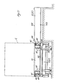
- With reference to Figures 1 to 3, the vertical stacking terminal for containers comprises at least one
corridor 1 having at both sides thereof a plurality ofstorage compartments 2 in a multiple-tier arrangement and designed to receive the containers C. The size and number ofcorridors 1 andstacking compartments 2, and therefore the number of containers C that can be received in the terminal depend upon the size of the containers C, the estimated yearly traffic, the maximum peak traffic and average dwell periods of the containers in the terminal. Preferably, and unlike the simplified illustration in the drawings, the vertical stacking terminal according to the invention comprises twoparallel corridors 1 withrespective stacking compartments 2. Thestacking compartments 2 associated with one of thecorridors 1 are intended for containers up to 20 ft. (6,1 m), and those associated with theother corridor 1 are intended for containers up to 40 ft. (12,2 m). - A lifting unit 3 is provided at least at one end, and preferably at both ends, of each
corridor 1. Moreover, in eachcorridor 1 there are providedrobot carriages 4 which are movable along the corridor onhorizontal runways 5 located at each tier or level of stackingcompartments 2 in registry with the bottom side thereof. Therobot carriages 4 may be in any number which may vary from a minimum of three to a maximum depending upon the maximum number of tiers of storage compartments 2. In the drawings, we have shown, for descriptive purposes, onerobot carriage 4 at each tier ofstorage compartments 2, but this is to be regarded as a limit case. - At ground level, at each end of the corridor/
s 1 of the stacking terminal, i.e. at each end side thereof, there are provided at least oneingress carriage 6 and at least one egress carriage 6' which are movable along rails 7. Saidrails 7 extend below the lifting unit/s 3 of the respective end side of the corridor/s 1 of the stacking terminal. Beside therails 7 for the ingress andegress carriages 6, 6' the invention provides, at one side of the lifting unit 3, at least one and preferably two ormore pedestals 8 for supporting the incoming containers and, at the opposite side of the lifting unit 3, at least one and preferably two or more pedestals 8' for the outgoing containers. Theingress carriage 6 moves between the lifting unit 3 and the pedestal/s 8 for the incoming containers, while the egress carriage 6' moves between the lifting unit 3 and the pedestal/s 8' for the outgoing containers. At least one portal or semi-portal crane for the loading and unloading operations (i.e. for handling the containers C between the quay and the stacking terminal and between the road and said terminal) may be moved to a position above thepedestals 8 and 8' at each end side of the stacking terminal. Preferably, one end side of the corridor/s of the stacking terminal and respective equipment may be specially deaigned for quay service, and the other end side of said corridor/s and respective equipment may be specially designed for road service. - At the outside, overhanging from the column of at least one of the lifting units 3, there may be provided a
maintenance workhop 10 that also may serve as a store forrobot carriages 4 and as an inlet and outlet area of robot carriages into and from thecorridor 1. The vertical stacking terminal may comprise any suitable self-supporting structure wherein the differential distortions of the maximum dimension are within controlled limits so as to guarantee the correct operation of all the machines in the terminal. The stacking terminal may be suitably protected and covered and it may be aerated, for example by natural ventilation. - With particular reference to Figures 4 to 7, each
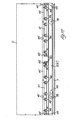
robot transfer carriage 4 at stacking level comprises abridge crane 11 having a framed construction of box-type beams and it moves throughwheels 12 onrunways 5. At least onewheel 12 at each end side of thebridge crane 11 is suitably powered at variable speed. Atransfer trolley 13 movable transversely of therunways 5 and designed to carry a container C is mounted on thebridge crane 11. Thetransfer trolley 13 comprises a container-supportingplatform 14 which may be lifted and lowered with respect to thetrolley 13 with the aid ofhydraulic jacks 15. In particular, thetransfer trolley 14 moves throughwheels 16 onrails 17 extending longitudinally of thebridge crane 11 from one end to the opposite end thereof, i.e. transversely of therunways 5, and getting aligned - when thebridge crane 4 is positioned in front of a pair of opposite stacking compartments 2 - withrails 18 provided on the bottom side of said stackingcompartments 2. Thetransfer trolley 13 can then get off either of the opposite end sides of thebridge crane 11 and enter (by moving on therails 17 of thebridge crane 11 and on therails 18 of the stacking compartments 2) either of the opposite stackingcompartments 2 in order to deposit therein (ensilage) or withdraw therefrom (de-ensilage) a container C, and thereafter it return to its position on thebridge crane 11. - Said movement of the
transfer trolley 13 with respect to thebridge crane 11 may be effected by any suitable means. In the embodiment shown in the Figures 6, 7 and 8, an upper ortop slider 19 and a lower orbottom slider 20 are arranged between thebridge crane 11 andtransfer trolley 13. Thelower slider 20 moves throughwheels 120 on thebridge crane 11 longitudinally of the latter, i.e. parallelly to therails 17 for thetransfer trolley 13, while theupper slider 19 moves in the same direction throughwheels 119 on thelower slider 20. The movement of thelower slider 20 with respect to thebridge crane 11 is effected by means ofchains 21 which are secured at their ends to both ends of thelower slider 20 as indicated at 22 and are passed around corresponding drivingsprocket wheels 23 mounted in the intermediate portion of thebridge crane 11. The movement of theupper slider 19 with respect to thelower slider 20 is effected by means ofchains 25 which are passed aroundsprocket wheels 24 arranged at the ends of thelower slider 20 and secured at 26 to the intermediate portion of thebridge crane 11 and at 27 to the intermediate portion of theupper slider 19. Similarly, the movement of thetransfer trolley 13 with respect to theupper slider 19 is effected by means ofchains 28 which are passed aroundsprocket wheels 30 arranged at the ends of theupper slider 19 and secured at 29 to the intermediate portion of thetransfer trolley 13. When thetransfer trolley 13 is in its retracted position on thebridge crane 11, the condition of the assembly is as shown in Figure 7, theupper slider 19 andlower slider 20 being then in a central position between thebridge crane 11 andtransfer trolley 13. By actuating the powered drivingsprocket wheels 23 in either direction, the translatory movements will be automatically obtained of thelower slider 20 with respect to thebridge crane 11, of theupper slider 19 with respect to thelower slider 20, and of thetransfer trolley 13 with respect to theupper slider 19. All these translatory movements take place in the same direction, i.e. toward either end of therobot carriage 4, and their summation corresponds to the stroke required by atransfer trolley 13 to enter either of the two opposite stackingcompartments 2. This condition is shown in Figure 8. The translatory speed of theupper slider 19 is greater than that of thelower slider 20, so that the former may also be called "fast"slider 19, whilst the latter may also be called "slow"slider 20. The translatory speed of thetransfer trolley 13 is greater than that of the upperfast slider 19. The return of thetransfer trolley 13 from its extended position of Figure 8 (or from the extended position off the opposite end of the slider 11) back to its retracted position on thebridge crane 11 as shown in Figure 7 is obtained by a reverse operation, i.e. by actuating thepowered sprocket wheels 23 in the opposite direction. - The
robot carriage 4 has the following operative cycle: to carry out the ensilage, i.e. to store into a stacking compartment 2 a container C disposed (over the lowered container-supporting platform 14) on the transfer trolley . 13 retracted in its intermediate position on the bridge crane 11 (see the upper portion of Figure 4), thebridge crane 11 moves on therunways 5 at the respective tier to the desired stackingcompartment 2. Thecontainer supporting platform 14 of thetransfer trolley 13 is then raised by thehydraulic jacks 15, thus lifting the container C from thetransfer trolley 13, and the latter is introduced as described above, together with the container C, into the stackingcompartment 2, as shown in the lower portion of Figure 4. When the centainer C has been completely introduced into the stackingcompartment 2, the container-supportingplatform 14 is lowered to lay down the container C onto thesuitable bearing members 32 in the stackingcompartment 2. Thetransfer trolley 13, then, moves back onto thebridge crane 11 as described above. To carry out the de-ensilage, i.e. to retrieve a container C from a stackingcompartment 2, the bridge crane moves on therunways 5 to the selected compartment and thetransfer trolley 13 is introduced, with its container-supportingplatform 14 in the lowered position, into the stackingcompartment 2 under the container C which is now supported by therespective bearing members 32. The container-supportingplatform 14 is then raised and picks up the container C by lifting it from the bearingmembers 32 of the compartment. Thetransfer trolley 13 is then moved back onto thebridge crane 11 and the container-supportingplatform 14 is lowered, to lay down the container C onto the fixed structure of saidtransfer trolley 13. - Each lifting unit 3 is formed substantially by a hydraulically-operated elevator actuated by electrical motors, preferably of a.c. type. The
cabin 33 of the elevator comprises at the bottom thereof twohorizontal beams 133 each provided with a section ofrunway 105 which may get into alignment with therunways 5 at stacking level as shown particularly in the Figures 9 and 10. When thecabin 33 of an elevator has reached the level of a tier of stackingcompartments 2, the sections ofrunways 105 of saidcabin 33 constitute an extension of therunways 5 of that tier and, therefore, permit the robot carriage to move on said sections ofrunways 105 into and out of thecabin 33 of the elevator. Thebeams 133 of theelevator cabin 33 with theirrunway sections 105 are mounted in said cabin so as to be raised and lowered therein between a lower position for inlet and outlet of a robot carriage 4 (shown with solid lines in Figure 9) and an upper position (shown with dot-and-dash lines in Figure 9). For this purpose, thebeams 133 supporting therunway sections 105 are secured tosliders 34 which are guided to slide vertically alongguide members 35 ofuprights 233 in theelevator cabin 33. The vertical displacement of saidsliders 34 may be obtained, for example, by means ofendless chains 36 which are secured at 136 to saidsliders 34 and are passed around direction-changingsprocket wheels 236 mounted at the top and bottom ends of theuprights 233 and suitably powered. - In the upper portion of the
elevator cabin 33 there are provided container-holding means constituted by a so--called "spreader", i.e. aframe 37 for suspending a container C.The suspending frame 37 is provided at the underside thereof withmeans 38 to hook or lock a container C. In this exemplary embodiment, the container-suspendingframe 37 is fixed in theelevator cabin 33, but in an alternative embodiment it may be raised and lowered to at least a limited extent. This type of container--suspending frames (so-called "spreaders") and their container--locking means 38 are well known to those skilled in the art and, therefore, their detailed description may be omitted. - An
ingress carriage 6 or egress carriage 6' at ground level is shown specifically in the Figures 11, 12 and 13. It is constituted by a railway type truck or the like moving on therails 7 through wheels 39- Preferably, at least a pair ofwheels 39 are actuated by asuitable motor 40, whereby said ingress andegress carriages 6, 6' are of self-propelled type. On each ingress oregress carriage 6, 6' there are provided one ormore transfer trolleys 41 which are arranged side by side and are movable throughwheels 42 alongrails 43 which are secured to thecarriage 6, 6' and are disposed transversely thereof, i.e. transversely of therails 7. When an ingress oregress carriage 6, 6' has moved close to one side of a supportingpedestal 8 or 8' for the incoming or outgoing containers, respectively, thetransverse rails 43 get into alignment withcorresponding rails 143 provided on the container-supportingpedestal 8 or 8', whereby thetransfer trolleys 41 of thecarriage 6, 6' may be displaced, on therails carriage 6, 6' onto thepedestal 8, 8' and then back onto thecarriage 6, 6'. This displacement of the transfer trolley/s 41 may be obtained by any suitable actuating means, for example by means oflinear actuators 44 of hydraulic or other nature. On the transfer trolley/s 41 there are provided container-supportingbeams 45 which will bear a container C laid on the ingress oregress carriage 6, 6' and which can be raised and lowered byhydraulic jacks 46. - Of course, the ingress and/or
egress carriages 6, 6' may be also constructed so that theirtransfer trolleys 41, with their respective container-raising and lowering means, may alternately get off either sides of the ingress and/oregress carriages 6, 6', to pick up and to lay down, as desired, a container from and onto container-supporting pedestals located at both sides of therails 7. - The vertical stacking terminal for containers as described above has the following operative cycles, which are the same at both ends of the
corridor 1, i.e. at both end sides of the terminal. - The
crane 9 lays down a container C onto the bearingmembers 108 of a container-supportingpedestal 8 for incoming containers. Aningress carriage 6 moves along therails 7 close to one side of said container-supportingpedestal 8, and itstransfer trolley 41 moves out transversely and laterally, with its container-supportingbeams 45 in the lowered position, to get onto therails 143 of the container-supportingpedestal 8 underneath the container C. The container-supportingbeams 45 of thetransfer trolley 41 are then raised, to raise and pick up the container C from the container-bearingmembers 108 of the container-supportingpedestal 8. Thetransfer trolley 41 is then retracted back onto theingress carriage 6, and the container-supportingbeams 45 are lowered. Theingress carriage 6 then moves onto therails 7 together with the container C to a position below the lifting unit 3 and then theempty elevator cabin 33 is lowered thereon. During the descent of thecabin 33, itsbottom beams 133 with therunway sections 105 are raised to their upper position, shown with dot-and-dash lines in Figure 9, to permit or facilitate the entrance of theingress carriage 6 with the container C into saidcabin 33. The container C is then locked to thespreader 37. This result can be achieved by merely lowering theelevator cabin 33 and/or lowering thespreader 37, and/or by raising the container C by means of the container-supportingbeams 45 andrespective jacks 46 to a position where it will be engaged by the locking means 38. Theelevator cabin 33, then, begins moving upward while theingress carriage 6 is moved out of the lifting unit 3 and is returned to its original position beside container--supportingpedestal 8 for incoming containers. - During the upward movement of the
elevator cabin 33, thebeams 133 with theirrunway sections 105 are lowered to their lower position, shown with solid lines in Figure 9, so that they will be aligned, when thecabin 33 reaches the selected tier, with therunways 5 of that tier. Therobot carriage 4 at the tier - with itstransfer trolley 13 retracted on thebridge crane 11 and with its container --supportingplatform 14 in the lowered position - will then enter theelevator cabin 33 and will withdraw the container C from thespreader 37. To achieve this result, saidspreader 37 may be lowered to lay down the container C onto thetransfer trolley 13 of therobot carriage 4 or - as in the illustrated embodiment of stationary spreader 37 - this result can be achieved by raising theentire robot carriage 4 by means of the verticallymovable beams 133 and/or the container-supportingplatform 14. Thereafter, therobot carriage 4 gets out of theelevator cabin 33 and moves to therunways 5 in registry with the pre-established stackingcompartment 2, where it deposits the container C through the ensilage operation described above with reference to Figures 4 to 8. - The selected container C is withdrawn from the respective stacking
compartment 2 by therobot carriage 4 at stacking level and through the de-ensilage operation described above with reference to Figures 4 to 8, while theelevator cabin 33 is raised up to this level with itsbeams 133 and supportedrunway sections 105 in their lowered position as shown with solid lines in Figure 9. Therobot carriage 4 enters theelevator cabin 33 and the container C is locked to thespreader 37 either by lowering saidspreader 37 or by raising theentire robot carriage 4 by means of the vertically-movable beams 133 and/or by raising the container C alone by means of the container--supportingplatform 14. Therobot carriage 4 at stacking level, then, gets out of theelevator cabin 33 on therunway 5 at that tier, while thecabin 33 is lowered to ground level. During this descent, the bottom beams 133 with therunway sections 105 are raised to their upper position shown with dot-and-dash lines in Figure 9. In the meantime, an empty egress carriage 6' moves to a position below the lifting unit 3 and then theempty elevator cabin 33 is lowered thereon to lay down the container C onto said egress carriage 6'. This deposition of the container C onto the egress carriage 6' and subsequent unlocking thereof from the locking means 38 of thespreader 37 may also be obtained by merely lowering theelevator cabin 33 and or by lowering thespreader 37 and/or by raising the container-supportingbeams 45 of the egress carriage 6'. - Thereafter, the egress carriage 6' with the container C gets out of the
elevator cabin 33 by moving on therails 7 and reaches close to one side of an egress container--supporting pedestal 8'. Thetransfer trolley 41 of the egress carriage 6' then moves transversely and laterally to the container-supporting pedestal 8', with the container--supportingbeams 45 raised together with said container C, and - by moving on therails 143 of the container supporting pedestal 8' - it brings the container C above the bearingmembers 108 of said pedestal 8'. The container-supportingbeams 45 are then lowered to lay down the container C onto the bearingmembers 108 of the egress container-supporting pedestal 8', after which thetransfer trolley 41 is retracted onto the egress carriage 6'. Thereafter, thecrane 9 picks up the container C from the container-supporting pedestal 8' and lays it down onto a further transport means. - A container C to be introduced into the terminal is laid down by the
crane 9 onto an ingress container--supportingpedestal 8 and is then picked up therefrom by theingress carriage 6 by means of itstransfer carriage 41 as described above. At the same time, an egress carriage 6' moves to a position below the lifting unit 3, while a container C to be retrieved from the terminal is withdrawn (de-ensilage) from the respective stackingcompartment 2 by means of therobot carriage 4 at stacking level as described above. Theelevator cabin 33 moves to said level with thebeams 133 andrespective runway sections 105 in their lowered position. The robot carriage at stacking level enters theelevator oabin 33, delivers the container 0 to thespreader 37 and then gets out of thecabin 33 on therunways 5 at that tier. Theelevator cabin 33 is then lowered to ground level and during this descent thebeams 133 with therunway sections 105 are raised. At ground level, theelevator cabin 33 lays down the outgoing container C, as described above, onto the egress carriage 6' waiting there. Theingress oarriage 6 and egress oarriage 6' are then moved simultaneously, whereby the egress carriage 6' gets out of thecabin 33 and moves to a position beside an egress container-supporting pedestal 8', while theingress carriage 6 enters theelevator cabin 33. The container C to be stored is picked up from the ingress carriage and locked to thespreader 37 of theelevator cabin 33 as described above, after which thecabin 33 is raised to the selected level comprising the stackingcompartment 2 wherein the incoming container is to be stored. During the upward movement thebeams 133 with therunway sections 105 are lowered. Therobot carriage 4 of said tier then enters theelevator cabin 33, withdraws the container C from thespreader 37 as described above and then gets out of saidcabin 33 together with the container C and moves to the front side of the selected stackingcompartment 2 to introduce and lay down therein (ensilage) the container, as described above. At the same time, at ground level, the egress carriage 6' delivers the container C onto the egress container-supporting pedestal 8', as described above. The egress carriage 6' andingress carriage 6 are then returned to their original positions, the former below the lifting unit 3 and the latter beside an ingress container-supportingpedestal 8, to repeat said cycle, while thecrane 9 delivers onto the ingress container-supporting pedestal 8 a new container C to be stacked and retrieves the just withdrawn container C which has been laid down onto the egress container-supporting pedestal 8'. - If desired, and particularly at ground level, the invention may also provide a transfer carriage to transfer the containers between the two lifting units 3 at the two ends of at least one of the
corridors 1 of the vertical stacking terminal. For this purpose, thecrane 9 at an end side of the terminal may lay down a container on a suitable transit container-supporting pedestal, located beside the lifting unit 3. Aningress carriage 6 or egress carriage 6' located below the lifting unit picks up the container C from the transit container-supporting pedestal and transfers it onto said transfer carriage which will reach the lifting unit 3 located at the opposite end side of the terminal, where an ingress oregress carriage 6 or 6', located below the lifting unit, picks up the container from the transfer carriage and delivers it to the container--holding means of said lifting unit. - Each lifting unit may also be used for the simple transfer of a
robot carriage 4 from one tier to another, while itsbeams 133 andrunway sections 105 are in the lowered position, so that therobot carriage 4 available at a tier may enter thecabin 33 of the lifting unit 3 and get out therefrom after it has been transferred to another desired tier. - Of course, the invention is not limited to the embodiments here shown and described, but changes and modifications, especially of constructional nature, may be made thereto by utilizing, for example, technical or functional equivalents, without departing from the basic principle set forth above and claimed hereinafter.
Claims (19)
Priority Applications (1)
| Application Number | Priority Date | Filing Date | Title |
|---|---|---|---|
| AT84107746T ATE33810T1 (en) | 1983-07-27 | 1984-07-04 | DEVICE FOR VERTICAL STACKING OF CONTAINERS. |
Applications Claiming Priority (2)
| Application Number | Priority Date | Filing Date | Title |
|---|---|---|---|
| IT1259483 | 1983-07-27 | ||
| IT12594/83A IT1171216B (en) | 1983-07-27 | 1983-07-27 | VERTICAL STORAGE TERMINAL FOR CONTAINERS |
Publications (3)
| Publication Number | Publication Date |
|---|---|
| EP0133472A2 true EP0133472A2 (en) | 1985-02-27 |
| EP0133472A3 EP0133472A3 (en) | 1986-06-04 |
| EP0133472B1 EP0133472B1 (en) | 1988-04-27 |
Family
ID=11141996
Family Applications (1)
| Application Number | Title | Priority Date | Filing Date |
|---|---|---|---|
| EP84107746A Expired EP0133472B1 (en) | 1983-07-27 | 1984-07-04 | Vertical stacking terminal for containers |
Country Status (5)
| Country | Link |
|---|---|
| EP (1) | EP0133472B1 (en) |
| AT (1) | ATE33810T1 (en) |
| BR (1) | BR8403720A (en) |
| DE (1) | DE3470726D1 (en) |
| IT (1) | IT1171216B (en) |
Cited By (22)
| Publication number | Priority date | Publication date | Assignee | Title |
|---|---|---|---|---|
| EP0396005A3 (en) * | 1989-05-02 | 1991-01-23 | COPLA FÖRDER-UND LAGERTECHNIK GESELLSCHAFT FÜR ANLAGENBAU mbH | High shelf for stocking and destocking trochoidal goods, especially paper rolls |
| FR2667101A1 (en) * | 1990-09-20 | 1992-03-27 | Shimizu Construction Co Ltd | STORAGE SYSTEM, APPLICABLE TO PARKING SPACES, AND TRANSFER METHOD. |
| DE4120923A1 (en) * | 1991-06-25 | 1993-01-07 | Krupp Industrietech | PIECE HANDLING DEVICE |
| EP0589844A1 (en) * | 1992-09-24 | 1994-03-30 | Claus Berndt | High-performance warehouse with storing and retrieving means for goods |
| EP0736470A1 (en) * | 1995-04-07 | 1996-10-09 | ELVECO msj S.A. | Transfer installation of containers for products flowing by gravity |
| US5615992A (en) * | 1993-11-24 | 1997-04-01 | Carl Schenck Ag | Method storing or restacking goods carriers in multi-storied warehouse |
| WO1997012820A1 (en) * | 1995-10-03 | 1997-04-10 | Daifuku Co., Ltd. | Running equipment |
| US6929440B1 (en) | 1998-12-15 | 2005-08-16 | Johann Walter Grond | Method and storage loading system for loading and unloading loads in storage |
| EP2527274A1 (en) * | 2011-05-25 | 2012-11-28 | SERVUS Intralogistik GmbH | Method and device for controlling a rail-bound transport robot in a materials store |
| KR20130050920A (en) * | 2010-03-12 | 2013-05-16 | 심보틱 엘엘씨 | Replenishment and order fulfillment system |
| CN104670776A (en) * | 2015-02-13 | 2015-06-03 | 苏州怡丰自动化装备有限公司 | Automated three-dimensional warehouse for placing round goods and goods incoming and outgoing method thereof |
| US9802759B2 (en) | 2003-08-29 | 2017-10-31 | Symbotic, LLC | Materials-handling system using autonomous transfer and transport vehicles |
| NO20181039A1 (en) * | 2018-06-12 | 2019-12-13 | Autostore Tech As | Storage system |
| CN110733819A (en) * | 2019-11-14 | 2020-01-31 | 北京三快在线科技有限公司 | Material transportation system and warehouse |
| CN111942795A (en) * | 2020-08-17 | 2020-11-17 | 东华大学 | An operation efficiency evaluation method for four-way vehicle intensive storage system |
| CN111977237A (en) * | 2020-08-19 | 2020-11-24 | 汪家烨 | Storage stacking equipment for intelligent logistics and working method thereof |
| US11352016B2 (en) | 2018-06-12 | 2022-06-07 | Autostore Technology AS | Storage system |
| US11479407B2 (en) | 2018-01-09 | 2022-10-25 | Autostore Technology AS | Displacement mechanism for a remotely operated vehicle |
| US11772685B2 (en) | 2018-06-12 | 2023-10-03 | Autostore Technology AS | System for storing and transporting storage containers |
| US11975744B2 (en) | 2018-06-12 | 2024-05-07 | Autostore Technology AS | Method and system for controlling the operation of container handling vehicles and drones serving an automated storage and retrieval system |
| US12179807B2 (en) | 2018-06-12 | 2024-12-31 | Autostore Technology AS | Automated storage system |
| US12179806B2 (en) | 2018-06-12 | 2024-12-31 | Autostore Technology AS | Method of operating an automated storage and retrieval system |
Families Citing this family (2)
| Publication number | Priority date | Publication date | Assignee | Title |
|---|---|---|---|---|
| DE102011014394C5 (en) | 2011-03-11 | 2022-02-17 | Ssi Schäfer Automation Gmbh | Circular roaming for a storage and picking system |
| TWI588071B (en) * | 2011-03-14 | 2017-06-21 | 辛波提克有限責任公司 | Replenishment and order fulfillment system |
Family Cites Families (4)
| Publication number | Priority date | Publication date | Assignee | Title |
|---|---|---|---|---|
| US3669288A (en) * | 1968-03-29 | 1972-06-13 | Kaiser Ind Corp | Method of handling and storing containers at a shipping terminal |
| US3583584A (en) * | 1969-08-18 | 1971-06-08 | Mcneil Corp | Warehousing |
| GB1295649A (en) * | 1969-11-25 | 1972-11-08 | ||
| DE2113202B2 (en) * | 1971-03-18 | 1976-09-02 | Hoffmann geb. Chvala, Maria, 5000Köln | Goods stores with vertically movable transfer equipment - has self-propelling transport units on rails of individual floors of vertical shelf rows |
-
1983
- 1983-07-27 IT IT12594/83A patent/IT1171216B/en active
-
1984
- 1984-07-04 EP EP84107746A patent/EP0133472B1/en not_active Expired
- 1984-07-04 DE DE8484107746T patent/DE3470726D1/en not_active Expired
- 1984-07-04 AT AT84107746T patent/ATE33810T1/en not_active IP Right Cessation
- 1984-07-26 BR BR8403720A patent/BR8403720A/en not_active IP Right Cessation
Cited By (43)
| Publication number | Priority date | Publication date | Assignee | Title |
|---|---|---|---|---|
| EP0396005A3 (en) * | 1989-05-02 | 1991-01-23 | COPLA FÖRDER-UND LAGERTECHNIK GESELLSCHAFT FÜR ANLAGENBAU mbH | High shelf for stocking and destocking trochoidal goods, especially paper rolls |
| FR2667101A1 (en) * | 1990-09-20 | 1992-03-27 | Shimizu Construction Co Ltd | STORAGE SYSTEM, APPLICABLE TO PARKING SPACES, AND TRANSFER METHOD. |
| DE4120923A1 (en) * | 1991-06-25 | 1993-01-07 | Krupp Industrietech | PIECE HANDLING DEVICE |
| EP0589844A1 (en) * | 1992-09-24 | 1994-03-30 | Claus Berndt | High-performance warehouse with storing and retrieving means for goods |
| US5615992A (en) * | 1993-11-24 | 1997-04-01 | Carl Schenck Ag | Method storing or restacking goods carriers in multi-storied warehouse |
| EP0736470A1 (en) * | 1995-04-07 | 1996-10-09 | ELVECO msj S.A. | Transfer installation of containers for products flowing by gravity |
| FR2732672A1 (en) * | 1995-04-07 | 1996-10-11 | Elveco Msj Sa | CONTAINER TRANSPORTATION SYSTEM FOR GRAVITY PRODUCTS |
| US5946217A (en) * | 1995-04-07 | 1999-08-31 | Elveco Msj S.A. | Installation for transporting containers for products flowing by gravity |
| WO1997012820A1 (en) * | 1995-10-03 | 1997-04-10 | Daifuku Co., Ltd. | Running equipment |
| US6929440B1 (en) | 1998-12-15 | 2005-08-16 | Johann Walter Grond | Method and storage loading system for loading and unloading loads in storage |
| US11485576B2 (en) | 2003-08-29 | 2022-11-01 | Symbotic Llc | Materials-handling system using autonomous transfer and transport vehicles |
| US9802759B2 (en) | 2003-08-29 | 2017-10-31 | Symbotic, LLC | Materials-handling system using autonomous transfer and transport vehicles |
| US10800606B2 (en) | 2003-08-29 | 2020-10-13 | Symbotic Llc | Materials-handling system using autonomous transfer and transport vehicles |
| US12071303B2 (en) | 2003-08-29 | 2024-08-27 | Symbotic Llc | Materials-handling system using autonomous transfer and transport vehicles |
| US9611097B2 (en) | 2010-03-12 | 2017-04-04 | Symbotic, LLC | Replenishment and order fulfillment system |
| KR20130050920A (en) * | 2010-03-12 | 2013-05-16 | 심보틱 엘엘씨 | Replenishment and order fulfillment system |
| US10233019B2 (en) | 2010-03-12 | 2019-03-19 | Symbotic, LLC | Replenishment and order fulfillment system |
| US12122603B1 (en) | 2010-03-12 | 2024-10-22 | Symbotic Llc | Replenishment and order fulfillment system |
| US10633184B2 (en) | 2010-03-12 | 2020-04-28 | Symbotic, LLC | Replenishment and order fulfillment system |
| JP2013522144A (en) * | 2010-03-12 | 2013-06-13 | シンボティック リミテッドライアビリティカンパニー | Replenishment and order processing system |
| US11760569B2 (en) | 2010-03-12 | 2023-09-19 | Symbotic Llc | Replenishment and order fulfillment system |
| US10994930B2 (en) | 2010-03-12 | 2021-05-04 | Symbotic Llc | Replenishment and order fulfillment system |
| EP2527274A1 (en) * | 2011-05-25 | 2012-11-28 | SERVUS Intralogistik GmbH | Method and device for controlling a rail-bound transport robot in a materials store |
| CN104670776A (en) * | 2015-02-13 | 2015-06-03 | 苏州怡丰自动化装备有限公司 | Automated three-dimensional warehouse for placing round goods and goods incoming and outgoing method thereof |
| US11548731B2 (en) | 2018-01-09 | 2023-01-10 | Autostore Technology AS | Displacement mechanism for a remotely operated vehicle |
| US11479407B2 (en) | 2018-01-09 | 2022-10-25 | Autostore Technology AS | Displacement mechanism for a remotely operated vehicle |
| NO346265B1 (en) * | 2018-06-12 | 2022-05-16 | Autostore Tech As | Storage system |
| US12179807B2 (en) | 2018-06-12 | 2024-12-31 | Autostore Technology AS | Automated storage system |
| US11352016B2 (en) | 2018-06-12 | 2022-06-07 | Autostore Technology AS | Storage system |
| US12448235B2 (en) | 2018-06-12 | 2025-10-21 | Autostore Technology AS | Storage system |
| US12428042B2 (en) | 2018-06-12 | 2025-09-30 | Autostore Technology AS | Method and system for controlling the operation of container handling vehicles and drones serving an automated storage and retrieval system |
| US12179806B2 (en) | 2018-06-12 | 2024-12-31 | Autostore Technology AS | Method of operating an automated storage and retrieval system |
| US12179808B2 (en) | 2018-06-12 | 2024-12-31 | Autostore Technology AS | System for storing and transporting storage containers |
| US11772685B2 (en) | 2018-06-12 | 2023-10-03 | Autostore Technology AS | System for storing and transporting storage containers |
| US11814058B2 (en) | 2018-06-12 | 2023-11-14 | Autostore Technology AS | Storage system |
| US11975744B2 (en) | 2018-06-12 | 2024-05-07 | Autostore Technology AS | Method and system for controlling the operation of container handling vehicles and drones serving an automated storage and retrieval system |
| NO20181039A1 (en) * | 2018-06-12 | 2019-12-13 | Autostore Tech As | Storage system |
| CN110733819A (en) * | 2019-11-14 | 2020-01-31 | 北京三快在线科技有限公司 | Material transportation system and warehouse |
| CN110733819B (en) * | 2019-11-14 | 2021-03-19 | 北京三快在线科技有限公司 | Material transportation system and warehouse |
| CN111942795A (en) * | 2020-08-17 | 2020-11-17 | 东华大学 | An operation efficiency evaluation method for four-way vehicle intensive storage system |
| CN111942795B (en) * | 2020-08-17 | 2021-11-12 | 东华大学 | Operation efficiency evaluation method for four-way vehicle dense warehousing system |
| CN111977237A (en) * | 2020-08-19 | 2020-11-24 | 汪家烨 | Storage stacking equipment for intelligent logistics and working method thereof |
| CN111977237B (en) * | 2020-08-19 | 2021-11-09 | 汪家烨 | Storage stacking equipment for intelligent logistics and working method thereof |
Also Published As
| Publication number | Publication date |
|---|---|
| EP0133472B1 (en) | 1988-04-27 |
| IT1171216B (en) | 1987-06-10 |
| EP0133472A3 (en) | 1986-06-04 |
| ATE33810T1 (en) | 1988-05-15 |
| IT8312594A1 (en) | 1985-01-27 |
| DE3470726D1 (en) | 1988-06-01 |
| IT8312594A0 (en) | 1983-07-27 |
| BR8403720A (en) | 1985-07-02 |
Similar Documents
| Publication | Publication Date | Title |
|---|---|---|
| EP0133472A2 (en) | Vertical stacking terminal for containers | |
| US12522437B2 (en) | Automated storage and retrieval system, a method of operating the system and a multi trolley vehicle | |
| US3608750A (en) | Storage means and load-handling equipment therefor | |
| US3543952A (en) | Container handling and storage system | |
| US3669288A (en) | Method of handling and storing containers at a shipping terminal | |
| AU2017232270B2 (en) | Transport and handover system for storing and removing or relocating storage goods in high-bay warehouses, and storage and retrieval machine | |
| CA2932890C (en) | Method and apparatus for storing and retrieving or shifting containers in high-bay warehouses | |
| CA2973384C (en) | Method and container transfer installation for placing containers into and removing containers from container storage areas | |
| NL8200975A (en) | TRANSPORTATION DEVICE FOR A STORAGE INSTALLATION. | |
| US5407316A (en) | Rapid, compact, high density storage of cargo containers | |
| US1522707A (en) | Freight-handling system | |
| US3583584A (en) | Warehousing | |
| CN112020468A (en) | Automated storage and retrieval system including a transfer module and method of operating the same | |
| JPS5854054B2 (en) | Container transport method and device | |
| DE2406378A1 (en) | WAREHOUSE EQUIPMENT | |
| EP0351374A1 (en) | An automated garage | |
| US3428195A (en) | Storage system with multi-level load handling means with a common loading and unloading level | |
| US6554557B1 (en) | Inter-box connector (IBC) installation and removal system | |
| EP0471411A1 (en) | Method and apparatus for loading and/or unloading goods, in particular goods stacked on pallets, generally for use with ships | |
| US1828308A (en) | Apparatus for handling and storing automobiles and the like | |
| US3833140A (en) | Load handling equipment | |
| US11273984B2 (en) | Storing, retrieving or moving containers in a high-bay warehouse | |
| WO1998035892A1 (en) | Marine cargo container overhead handling and storage | |
| DE4311146A1 (en) | Rapid-transfer terminal | |
| DE9321200U1 (en) | Rapid transshipment terminal |
Legal Events
| Date | Code | Title | Description |
|---|---|---|---|
| PUAI | Public reference made under article 153(3) epc to a published international application that has entered the european phase |
Free format text: ORIGINAL CODE: 0009012 |
|
| AK | Designated contracting states |
Designated state(s): AT BE CH DE FR GB LI LU NL SE |
|
| PUAL | Search report despatched |
Free format text: ORIGINAL CODE: 0009013 |
|
| AK | Designated contracting states |
Kind code of ref document: A3 Designated state(s): AT BE CH DE FR GB LI LU NL SE |
|
| 17P | Request for examination filed |
Effective date: 19860728 |
|
| 17Q | First examination report despatched |
Effective date: 19870309 |
|
| GRAA | (expected) grant |
Free format text: ORIGINAL CODE: 0009210 |
|
| AK | Designated contracting states |
Kind code of ref document: B1 Designated state(s): AT BE CH DE FR GB LI LU NL SE |
|
| PG25 | Lapsed in a contracting state [announced via postgrant information from national office to epo] |
Ref country code: LI Effective date: 19880427 Ref country code: CH Effective date: 19880427 Ref country code: AT Effective date: 19880427 |
|
| REF | Corresponds to: |
Ref document number: 33810 Country of ref document: AT Date of ref document: 19880515 Kind code of ref document: T |
|
| REF | Corresponds to: |
Ref document number: 3470726 Country of ref document: DE Date of ref document: 19880601 |
|
| ET | Fr: translation filed | ||
| PG25 | Lapsed in a contracting state [announced via postgrant information from national office to epo] |
Ref country code: LU Free format text: LAPSE BECAUSE OF NON-PAYMENT OF DUE FEES Effective date: 19880731 |
|
| REG | Reference to a national code |
Ref country code: CH Ref legal event code: PL |
|
| PLBE | No opposition filed within time limit |
Free format text: ORIGINAL CODE: 0009261 |
|
| STAA | Information on the status of an ep patent application or granted ep patent |
Free format text: STATUS: NO OPPOSITION FILED WITHIN TIME LIMIT |
|
| 26N | No opposition filed | ||
| PGFP | Annual fee paid to national office [announced via postgrant information from national office to epo] |
Ref country code: GB Payment date: 19930628 Year of fee payment: 10 |
|
| PG25 | Lapsed in a contracting state [announced via postgrant information from national office to epo] |
Ref country code: GB Effective date: 19940704 |
|
| PGFP | Annual fee paid to national office [announced via postgrant information from national office to epo] |
Ref country code: FR Payment date: 19950130 Year of fee payment: 11 |
|
| EAL | Se: european patent in force in sweden |
Ref document number: 84107746.4 |
|
| PGFP | Annual fee paid to national office [announced via postgrant information from national office to epo] |
Ref country code: SE Payment date: 19950131 Year of fee payment: 11 |
|
| GBPC | Gb: european patent ceased through non-payment of renewal fee |
Effective date: 19940704 |
|
| PG25 | Lapsed in a contracting state [announced via postgrant information from national office to epo] |
Ref country code: SE Effective date: 19950705 |
|
| EUG | Se: european patent has lapsed |
Ref document number: 84107746.4 |
|
| PG25 | Lapsed in a contracting state [announced via postgrant information from national office to epo] |
Ref country code: FR Effective date: 19960430 |
|
| REG | Reference to a national code |
Ref country code: FR Ref legal event code: ST |
|
| REG | Reference to a national code |
Ref country code: FR Ref legal event code: ST |
|
| REG | Reference to a national code |
Ref country code: FR Ref legal event code: ST |
|
| PGFP | Annual fee paid to national office [announced via postgrant information from national office to epo] |
Ref country code: DE Payment date: 20000707 Year of fee payment: 17 |
|
| PGFP | Annual fee paid to national office [announced via postgrant information from national office to epo] |
Ref country code: BE Payment date: 20000717 Year of fee payment: 17 |
|
| PGFP | Annual fee paid to national office [announced via postgrant information from national office to epo] |
Ref country code: NL Payment date: 20000731 Year of fee payment: 17 |
|
| PG25 | Lapsed in a contracting state [announced via postgrant information from national office to epo] |
Ref country code: BE Free format text: LAPSE BECAUSE OF NON-PAYMENT OF DUE FEES Effective date: 20010731 |
|
| BERE | Be: lapsed |
Owner name: ITALIMPIANTI SOCIETA ITALIANA IMPIANTI P.A. Effective date: 20010731 |
|
| PG25 | Lapsed in a contracting state [announced via postgrant information from national office to epo] |
Ref country code: NL Free format text: LAPSE BECAUSE OF NON-PAYMENT OF DUE FEES Effective date: 20020201 |
|
| NLV4 | Nl: lapsed or anulled due to non-payment of the annual fee |
Effective date: 20020201 |
|
| PG25 | Lapsed in a contracting state [announced via postgrant information from national office to epo] |
Ref country code: DE Free format text: LAPSE BECAUSE OF NON-PAYMENT OF DUE FEES Effective date: 20020501 |