EP0133089A1 - Direct current power control circuit with overload and short circuit protection - Google Patents
Direct current power control circuit with overload and short circuit protection Download PDFInfo
- Publication number
- EP0133089A1 EP0133089A1 EP84401456A EP84401456A EP0133089A1 EP 0133089 A1 EP0133089 A1 EP 0133089A1 EP 84401456 A EP84401456 A EP 84401456A EP 84401456 A EP84401456 A EP 84401456A EP 0133089 A1 EP0133089 A1 EP 0133089A1
- Authority
- EP
- European Patent Office
- Prior art keywords
- circuit
- door
- output
- input
- overload
- Prior art date
- Legal status (The legal status is an assumption and is not a legal conclusion. Google has not performed a legal analysis and makes no representation as to the accuracy of the status listed.)
- Withdrawn
Links
- 238000007493 shaping process Methods 0.000 claims abstract description 6
- 230000005764 inhibitory process Effects 0.000 claims description 2
- 230000000737 periodic effect Effects 0.000 claims description 2
- 230000010355 oscillation Effects 0.000 abstract description 3
- 230000002401 inhibitory effect Effects 0.000 abstract 1
- 230000007246 mechanism Effects 0.000 abstract 1
- 239000003990 capacitor Substances 0.000 description 13
- 235000021183 entrée Nutrition 0.000 description 4
- 230000005284 excitation Effects 0.000 description 3
- 230000001052 transient effect Effects 0.000 description 3
- 230000000694 effects Effects 0.000 description 2
- 238000005259 measurement Methods 0.000 description 2
- 229920006395 saturated elastomer Polymers 0.000 description 2
- 230000035945 sensitivity Effects 0.000 description 2
- 241001080024 Telles Species 0.000 description 1
- 230000006378 damage Effects 0.000 description 1
- 238000010586 diagram Methods 0.000 description 1
- 230000008034 disappearance Effects 0.000 description 1
- 238000005265 energy consumption Methods 0.000 description 1
- 238000012986 modification Methods 0.000 description 1
- 230000004048 modification Effects 0.000 description 1
- 244000045947 parasite Species 0.000 description 1
- 230000003071 parasitic effect Effects 0.000 description 1
- 230000000087 stabilizing effect Effects 0.000 description 1
- 230000007704 transition Effects 0.000 description 1
- 230000001960 triggered effect Effects 0.000 description 1
Images

Classifications
-
- H—ELECTRICITY
- H02—GENERATION; CONVERSION OR DISTRIBUTION OF ELECTRIC POWER
- H02H—EMERGENCY PROTECTIVE CIRCUIT ARRANGEMENTS
- H02H3/00—Emergency protective circuit arrangements for automatic disconnection directly responsive to an undesired change from normal electric working condition with or without subsequent reconnection ; integrated protection
- H02H3/02—Details
- H02H3/06—Details with automatic reconnection
-
- H—ELECTRICITY
- H02—GENERATION; CONVERSION OR DISTRIBUTION OF ELECTRIC POWER
- H02H—EMERGENCY PROTECTIVE CIRCUIT ARRANGEMENTS
- H02H3/00—Emergency protective circuit arrangements for automatic disconnection directly responsive to an undesired change from normal electric working condition with or without subsequent reconnection ; integrated protection
- H02H3/08—Emergency protective circuit arrangements for automatic disconnection directly responsive to an undesired change from normal electric working condition with or without subsequent reconnection ; integrated protection responsive to excess current
- H02H3/087—Emergency protective circuit arrangements for automatic disconnection directly responsive to an undesired change from normal electric working condition with or without subsequent reconnection ; integrated protection responsive to excess current for dc applications
Definitions
- the invention relates to direct current power control circuits and, more particularly, to those which are used for controlling actuators in automatic systems, from control signals delivered at certain times to the outputs of the automatic system.
- These actuators relays, incandescent lamps, motors, solenoid valves or others, may need a relatively large power and when the device is produced in the form of an integrated circuit the output amplifier which it comprises does not can withstand without destruction the powers absorbed by the load in the event of an overload or short-circuit thereon.
- a way must therefore be found to significantly reduce the current flowing through the output amplifier as soon as an overload occurs and to immediately restore normal current as soon as the overload has disappeared.
- This device has the disadvantage of requiring a clock, therefore additional components and occupied surface on the circuit boards, and entailing additional energy consumption due to the permanent operation of the clock.
- a limitation loop comprising a threshold switch 7 and a circuit 8 for timing on switching on and on. trigger.
- the latter is triggered by a closure, even very brief, of the switch 7, hence the disadvantage of sensitivity to parasitic pulses transmitted by the current sensor and the threshold switch.
- the limitation loop comprises a threshold switch 6 and a digital timer 9 - 10-13 with a clock 14 downstream of switch 6.
- the invention relates to a device free of nien disad- t s above, wherein the cutting of the output current in the event of overload is obtained by internal relaxation of a loop-reaction against, without using a clock external to said loop, and in which said loop is analog and undergoes no disturbance brief spurious pulses transmitted from the sensor.
- This device also applies an increasing duty cycle during the lighting of a conventional incandescent lamp, which accelerates the lighting.
- the device comprises a door, an input of which receives an on / off control signal, an output amplifier controlled via this door, a feedback loop comprising a device for detecting an overcurrent of the output current of the amplifier and means, controlled by an overcurrent signal delivered by said member, to apply to the other input of the door in the event of overload or short circuit, a logic signal of periodic inhibition obtained by relaxation of the loop feedback at an appropriate rate so that the output power of the circuit is reduced to a temporarily acceptable value for the amplifier of the circuit, and is characterized in that, according to a preferred embodiment, said door is a door OR, and in that there are provided reaction means added to the door to constitute the threshold shaping circuit.
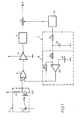
- an all-or-nothing control signal is applied to a light-emitting diode 10 (for example by infrared) which is part of a photocoupler 1 further comprising a phototransistor 11 having a collector load resistor 12.
- This photocoupler constitutes an inverter whose output is connected to the input 21 of an OR gate 2 with two inputs 21 and 22.
- the output of this OR gate directly controls an amplifier-inverter 3 of which the output is connected, by an instantaneous current limiting device 4 and a current measurement sensor 5, to an output terminal S.
- the intensity measurement signal from the sensor 5 is applied to an overcurrent detector 6, the output of which is connected to a threshold shaping circuit 8 via an integrator circuit 7; the output of circuit 8 is connected to the second input 22 of door 2.
- the integrator circuit 7 comprises a resistor 70 and a capacitor 71
- the trigger circuit 8 comprises a differential amplifier 80 and a reference DC voltage source 81, the positive terminal of which is connected to the negative input of the amplifier 80.
- the positive input of the amplifier 80 is connected to the point common to the resistor 70 and to the capacitor 71 by a resistor 801, and to the terminal 22 by a resistor 802.
- the current sensor 5 transmits an overcurrent signal to the detector 6, the output of which then passes to logic level 1; the capacitor of the integrator 7 is charged and, after a delay fixed by the resistor 70 and the capacitor 71, the integrated signal exceeds the switching threshold of 0 to 1 of the circuit 8, so that the output of the latter goes to 1, as well as input 22 of door 2.
- the output of this door then changes to 1, which causes the output of the inverting amplifier to zero. 3.
- the flow rate of the output in short circuit is then interrupted and the overcurrent signal from the sensor 5 is canceled.
- the output of the detector 6 then goes back to zero again and the capacitor 71 begins to discharge.
- the initial current can reach the order ten times the nominal current and then decrease to this nominal value in a few tens of milliseconds.
- the limiter 4 protects the amplifier 3 against too large a current demand and the relaxation cutting mode is set in service.
- the device delivers an output energy sufficient to quickly heat the filament and thus bring it to its nominal speed. The overcurrent signal would then disappear, which allows the inverting amplifier 3 to continuously power the lamp until the control signal is interrupted.
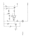
- the photocoupler circuit 1 comprises, in addition to the elements 10-11-12 of FIG. 1, a Zener diode 13 for stabilizing the voltage.
- the output of the OR gate 2 is connected, via a resistor 31, to the base of a PNP type transistor 32 which constitutes the output inverting amplifier.
- the emitter of transistor 32 is connected to the positive pole + V via a resistor 50 and a Zener diode 4 is connected in parallel to the series circuit consisting of resistor 50 and the base-emitter junction of the transistor 32, the anode of the Zener diode being connected to the transistor.
- the feedback resistor 50 associated with the Zener diode 4 for limiting the base control voltage of the transistor 32, constitute an instantaneous current limiter.
- the overcurrent detector member 6 (FIG. 1) is constituted by a PNP type transistor 61, the base of which is connected, by a resistor 62, to the common point between the resistor 5 and the transistor 32 and whose collector is connected to the capacitor. 71 of the integrator 70-71 by a diode 72.
- the point common to the resistor 70 and to the capacitor 71 is connected to the input 22 of the gate 2 by a resistor 83 and, by a resistor 90, to the point common to the Zener diode 13, to the phototransistor 11 and to a generator.
- constant current 9 whose opposite terminal is connected to the OV of the power source.
- a resistor 82 connects the inlet 22 to the outlet of the door 2.
- the operation of the circuit of FIG. 2 is as follows: When the diode 10 receives a control signal, the phototransistor 11 is saturated. Its collector then applies a logic zero to input 21 of door 2, the other input 22 of which, in the absence of overcurrent, is zero.
- the output of gate 2 therefore goes to zero and, via the resistor 31, controls the base of the output transistor 32. In the absence of overload, this transistor is then saturated and can supply a load connected between the S and OV terminals. When the control current is interrupted, the input 21 and the output of the gate 2 again pass to 1, which blocks the output transistor 31.
- the voltage present across the resistor 50 controls the conduction of the overcurrent detector transistor 61 which, in series with the diode 72 and the resistor 70, discharges the capacitor 71.
- the gate 2 thanks to the resistance bridge 82, 83, in addition to its OR function, fulfills a shaping function with a threshold equivalent to that of the circuit 8 of FIG. 1, but with simplified mounting.
- the circuit of FIG. 2 gives the same transient regime for the ignition of incandescent lamps initially involving the detector 61, the integrator 70, 71, 72 and the threshold circuit 2, 82, 83.
- the invention also covers simplified versions of the circuits which would not include an instantaneous current limiter and any other embodiment implementing the same cutting, by relaxation of a loop, of the output voltage in the event of overcurrent.
Landscapes
- Circuit Arrangement For Electric Light Sources In General (AREA)
- Dc-Dc Converters (AREA)
Abstract
Description
L'invention se rapporte aux circuits de commande de puissance à courant continu et, plus particulièrement, à ceux qui sont utilisés pour la commande des actionneurs dans les automatismes, à partir de signaux de commande délivrés à certains moments aux sorties de l'automatisme. Ces actionneurs : relais, lampes à incandescence, moteurs, électro-vannes ou autres, peuvent avoir besoin d'une puissance relativement importante et lorsque le dispositif est réalisé sous la forme d'un circuit intégré l'amplificateur de sortie qu'il comporte ne peut supporter sans destruction les puissances absorbées par la charge en cas de surcharge ou de court-circuit sur celle-ci. Il faut alors trouver un moyen de réduire notablement le courant qui traverse l'amplificateur de sortie dès qu'une surcharge se manifeste et de rétablir immédiatement le courant normal dès que la surcharge a disparu.The invention relates to direct current power control circuits and, more particularly, to those which are used for controlling actuators in automatic systems, from control signals delivered at certain times to the outputs of the automatic system. These actuators: relays, incandescent lamps, motors, solenoid valves or others, may need a relatively large power and when the device is produced in the form of an integrated circuit the output amplifier which it comprises does not can withstand without destruction the powers absorbed by the load in the event of an overload or short-circuit thereon. A way must therefore be found to significantly reduce the current flowing through the output amplifier as soon as an overload occurs and to immediately restore normal current as soon as the overload has disappeared.
Dans le brevet français 2254136 déposé par Siemens Aktiengesellschaft le 27 Novembre 1974, on a décrit un dispositif de protection comportant une porte ET dont une entrée reçoit le signal de commande et dont la sortie est reliée à l'amplificateur de sortie. Dans la sortie de cet amplificateur sont montés un organe limiteur de courant suivi d'un organe capteur. Une tension prélevée aux bornes de cet organe capteur est appliquée à un comparateur à seuil qui commande une bascule. Lorsque celle-ci a été commutée par la détection d'une surintensité, elle transmet, à l'autre entrée de la porte ET, des impulsions engendrées par une horloge, ce qui a pour effet de découper le courant de sortie donc de le réduire à une valeur acceptable pendant l'existence de la surcharge.In French patent 2254136 filed by Siemens Aktiengesellschaft on November 27, 1974, a protection device has been described comprising an AND gate, one input of which receives the control signal and the output of which is connected to the output amplifier. In the output of this amplifier are mounted a current limiting member followed by a sensor member. A voltage taken from the terminals of this sensor member is applied to a threshold comparator which controls a rocker. When this has been switched by detecting an overcurrent, it transmits, to the other input of the AND gate, pulses generated by a clock, which has the effect of cutting the output current and therefore reducing it to an acceptable value during the existence of the overload.
Ce dispositif présente l'inconvénient de nécessiter une horloge, donc des composants et une surface occupée supplémentaires sur les cartes de circuits, et d'entraîner une consommation supplémentaire d'énergie due au fonctionnement permanent de l'horloge.This device has the disadvantage of requiring a clock, therefore additional components and occupied surface on the circuit boards, and entailing additional energy consumption due to the permanent operation of the clock.
Selon DE-A-2 640 337 (BBC), entre le capteur de courant 6 et la porte de commande 2, il est prévu une boucle de limitation comportant un interrupteur 7 à seuil et un circuit 8 de temporisation à l'enclenchement et au déclenchement. Ce dernier est déclenché par une fermeture, même très brève, de l'interrupteur 7, d'où l'inconvénient d'une sensibilité aux impulsions parasites transmises par le capteur de courant et l'interrupteur à seuil.According to DE-A-2 640 337 (BBC), between the current sensor 6 and the
Selon un brevet BBC ultérieur : FR-A-497 014, entre le capteur 5 et la porte de commande 2, la boucle de limitation comporte un interrupteur à seuil 6 et un retardateur numérique 9-10-13 avec une horloge 14 en aval de l'interrupteur 6.According to a subsequent BBC patent: FR-A-497,014, between the sensor 5 and the
De brèves fermetures de l'interrupteur 6 perturbent moins ce circuit que celui de DE-A-2 640 337, mais une certaine sensibilité aux parasites subsiste. On notera que la boucle de limitation est essentiellement numérique.Brief closings of switch 6 disturb this circuit less than that of DE-A-2 640 337, but a certain sensitivity to parasites remains. Note that the limitation loop is essentially digital.
L'invention a pour objet un dispositif exempt des inconvé- nients ci-dessus, dans lequel le découpage du courant de sortie en cas de surcharge est obtenu par la relaxation interne d'une boucle de contre-réaction, sans faire appel à une horloge extérieure à ladite boucle, et dans lequel ladite boucle est analogique et ne subit aucune perturbation de brèves impulsions parasites transmises depuis le capteur. Ce dispositif applique en outre un courant de rapport cyclique croissant pendant l'allumage d'une lampe à incandescence classique, ce qui en accélère l'allumage.The invention relates to a device free of nien disad- t s above, wherein the cutting of the output current in the event of overload is obtained by internal relaxation of a loop-reaction against, without using a clock external to said loop, and in which said loop is analog and undergoes no disturbance brief spurious pulses transmitted from the sensor. This device also applies an increasing duty cycle during the lighting of a conventional incandescent lamp, which accelerates the lighting.
Le dispositif suivant l'invention comporte une porte dont une entrée reçoit un signal de commande par tout ou rien, un amplificateur de sortie commandé via cette porte, une boucle de contre-réaction comprenant un organe détecteur de surintensité du courant de sortie de l'amplificateur et des moyens, commandés par un signal de surintensité délivré par ledit organe, d'appliquer à l'autre entrée de la porte en cas de surcharge ou de court-circuit, un signal logique d'inhibition périodique obtenu par relaxation de la boucle de contre-réaction à une cadence appropriée pour que la puissance de sortie du circuit soit réduite à une valeur temporairement acceptable pour l'amplificateur du circuit, et est caractérisé en ce que, selon un mode d'exécution préféré, ladite porte est une porte OU, et en ce qu'il est prévu des moyens de réaction adjoints à la porte pour constituer le circuit de mise en forme à seuil.The device according to the invention comprises a door, an input of which receives an on / off control signal, an output amplifier controlled via this door, a feedback loop comprising a device for detecting an overcurrent of the output current of the amplifier and means, controlled by an overcurrent signal delivered by said member, to apply to the other input of the door in the event of overload or short circuit, a logic signal of periodic inhibition obtained by relaxation of the loop feedback at an appropriate rate so that the output power of the circuit is reduced to a temporarily acceptable value for the amplifier of the circuit, and is characterized in that, according to a preferred embodiment, said door is a door OR, and in that there are provided reaction means added to the door to constitute the threshold shaping circuit.
L'invention sera mieux comprise à la lumière de la description ci-après.The invention will be better understood in the light of the description below.
Au dessin annexé :
- La figure 1 est un schéma de principe d'un circuit de commande conforme à l'invention dont,
- La figure 2 donne une forme d'exécution préférée, et
- Les figures 3 et 4 représentent respectivement la tension aux bornes du condensateur 71 et le courant de sortie Is lorsque la charge est une lampe à filament à coefficient de température positif.
- FIG. 1 is a block diagram of a control circuit according to the invention,
- FIG. 2 gives a preferred embodiment, and
- Figures 3 and 4 respectively represent the voltage across the capacitor 71 and the output current Is when the load is a filament lamp with positive temperature coefficient.
Dans le dispositif de la figure 1, un signal de commande par tout ou rien est appliqué à une diode émettrice de lumière 10 (par exemple par infra-rouge) qui fait partie d'un photo- coupleur 1 comprenant en outre un phototransistor 11 ayant une résistance de charge de collecteur 12. Ce photocoupleur constitue un inverseur dont la sortie est reliée à l'entrée 21 d'une porte OU 2 à deux entrées 21 et 22. La sortie de cette porte OU commande directement un amplificateur-inverseur 3 dont la sortie est reliée, par un dispositif limiteur instantané d'intensité 4 et un capteur de mesure de courant 5, à une borne de sortie S.In the device of FIG. 1, an all-or-nothing control signal is applied to a light-emitting diode 10 (for example by infrared) which is part of a photocoupler 1 further comprising a
Le signal de mesure d'intensité issu du capteur 5 est appliqué à un détecteur de surintensité 6 dont la sortie est reliée à un circuit de mise en forme à seuil 8 par l'intermédiaire d'un circuit intégrateur 7 ; la sortie du circuit 8 est reliée à la deuxième entrée 22 de la porte 2.The intensity measurement signal from the sensor 5 is applied to an overcurrent detector 6, the output of which is connected to a threshold shaping circuit 8 via an integrator circuit 7; the output of circuit 8 is connected to the
Le circuit intégrateur 7 comprend une résistance 70 et un condensateur 71, tandis que le circuit de déclenchement 8 comprend un amplificateur différentiel 80 et une source de tension continue de référence 81, dont la borne positive est reliée à l'entrée négative de l'amplificateur 80. L'entrée positive de l'amplificateur 80 est reliée au point commun à la résistance 70 et au condensateur 71 par une résistance 801, et à la borne 22 par une résistance 802.The integrator circuit 7 comprises a
Le fonctionnement du dispositif de la figure 1 est le suivant :
- Lorsque la
diode 10 reçoit un signal de commande, ce signal est transformé en un zéro logique par le photocoupleur et appliqué à l'une des entrées de laporte 2. En l'absence de surintensité, la sortie du circuit 8 est à zéro et laporte 2 reçoit donc deux zéros logiques et applique un zéro à l'entrée de l'amplificateur-inverseur 3, dont la sortie passe alors à l'état logique "1". Par l'intermédiaire du limiteur instantané d'intensité 4 et du capteur de courant 5, ce signal de sortie est transmis à la borne S et la tension correspondante alimente la charge raccordée à cette borne. Si ladite charge et ladite tension de sortie sont telles que le débit, en régime établi, reste inférieur au seuil du détecteur de surintensité 6, la sortie de ce détecteur reste à zéro et ce niveau logique zéro est transmis par le circuit 8 à l'entrée 22 de laporte 2. Pendant toute la durée du signal de commande, la charge est donc normalement alimentée.
- When the
diode 10 receives a control signal, this signal is transformed into a logic zero by the photocoupler and applied to one of the inputs of thegate 2. In the absence of an overcurrent, the output of the circuit 8 is at zero andgate 2 therefore receives two logic zeros and applies a zero to the input of the invertingamplifier 3, the output of which then changes to logic state "1". Via theinstantaneous current limiter 4 and the current sensor 5, this output signal is transmitted to terminal S and the corresponding voltage supplies the load connected to this terminal. If said load and said output voltage are such that the flow rate, in steady state, remains below the threshold of the overcurrent detector 6, the output of this detector remains at zero and this zero logic level is transmitted by the circuit 8 to theinput 22 of thedoor 2. During all the duration of the control signal, the load is therefore normally supplied.
Si un court-circuit se produit dans la charge, lorsque l'excitation de la diode 10 fait passer de 1 à zéro l'entrée 21 de la porte 2, l'autre entrée 22 étant à zéro, cette porte transmet un zéro à l'amplificateur inverseur 3, dont la sortie passe à 1, délivrant ainsi le courant d'alimentation destiné à la charge. Cette charge étant en court-circuit, le limiteur instantané d'intensité 4 limite le débit à une valeur supportable, en régime transitoire, pour l'amplificateur 3.If a short circuit occurs in the load, when the excitation of the
Le capteur de courant 5 transmet un signal de surintensité au détecteur 6, dont la sortie passe alors au niveau logique 1 ; le condensateur de l'intégrateur 7 se charge et, après un délai fixé par la résistance 70 et le condensateur 71, le signal intégré dépasse le seuil de commutation de 0 vers 1 du circuit 8, si bien que la sortie de ce dernier passe à 1, de même que l'entrée 22 de la porte 2. La sortie de cette porte passe alors à 1, ce qui fait passer à zéro la sortie de l'amplificateur-inverseur 3. Le débit de la sortie en court-circuit est alors interrompu et le signal de surintensité issu du capteur 5 s'annule. La sortie du détecteur 6 passe alors de nouveau à zéro et le condensateur 71 commence à se décharger.The current sensor 5 transmits an overcurrent signal to the detector 6, the output of which then passes to logic level 1; the capacitor of the integrator 7 is charged and, after a delay fixed by the
Lorsque la tension aux bornes du condensateur 71 passe en deçà du seuil de commutation de 1 vers 0 du circuit 8, la sortie de ce dernier passe à zéro, ainsi que l'entrée 22 de la porte 2. L'excitation de la diode 10 étant maintenue, l'entrée 21 de la porte 2 est encore au niveau zéro si bien que, la sortie de cette porte passe de nouveau à zéro et la sortie de l'amplificateur-inverseur 3 passe de nouveau à "1". Le courant limite s'établit de nouveau dans la charge en court-circuit, le signal de surintensité fait de nouveau passer à "1" la sortie du détecteur 6 et le cycle de charge du condensateur 71 recommence.When the voltage across the capacitor 71 drops below the 1 to 0 switching threshold of circuit 8, the output of the latter goes to zero, as well as
Il ressort de la description ci-dessus qu'en présence d'un court-circuit de sortie, le circuit de la figure 1 engendre des oscillations de relaxation, ce qui a pour effet de limiter le débit instantané et la dissipation moyenne à des valeurs acceptables pour l'amplificateur 3.It appears from the above description that in the presence of an output short circuit, the circuit of FIG. 1 generates relaxation oscillations, which has the effect of limiting the instantaneous flow rate and the average dissipation to values acceptable for
Si, pendant ce fonctionnement en découpage du courant de sortie par relaxation, la charge de sortie passe du court-circuit à une impédance compatible avec les caractéristiques normales du dispositif, le signal de surintensité disparaît. La relaxation de la boucle refermée par l'intégrateur 7 et le circuit de déclenchement 8 s'interrompt ; l'entrée 22 de la porte 2 reste à zéro et le signal appliqué à la diode 10 est normalement transmis par la porte 2 ; la sortie de l'amplificateur-inverseur 3, reste alors alimentée en régime établi jusqu'à l'interruption du signal de commande appliqué à la diode 10.If, during this cut-off operation of the output current by relaxation, the output load goes from the short circuit to an impedance compatible with the normal characteristics of the device, the overcurrent signal disappears. The relaxation of the loop closed by the integrator 7 and the trigger circuit 8 is interrupted; the
Dans le cas particulier où le circuit de la figure 1 est utilisé pour l'alimentation d'une lampe à incandescence, à la mise sous tension de cette lampe, ayant son filament froid, par un commutateur, le courant initial peut atteindre l'ordre de grandeur de dix fois le courant nominal et décroître ensuite jusqu'à cette valeur nominale en quelques dizaines de millisecondes.In the particular case where the circuit of FIG. 1 is used for the supply of an incandescent lamp, when the lamp is turned on, having its filament cold, by a switch, the initial current can reach the order ten times the nominal current and then decrease to this nominal value in a few tens of milliseconds.
A la mise sous tension d'une telle lampe à incandescence par le circuit de la figure 1, le limiteur 4 assure la protection de l'amplificateur 3 contre un appel de courant trop important et le régime de découpage par relaxation est mis en service. Le dispositif délivre une énergie de sortie suffisante pour échauffer rapidement le filament et l'amener ainsi à son régime nominal. Le signal de surintensité dispa- rait alors, ce qui permet à l'amplificateur-inverseur 3 d'aLimenter la lampe en permanence jusqu'à l'interruption du signal de commande.When this incandescent lamp is switched on by the circuit in FIG. 1, the
Dans l'exemple pratique de la figure 2, on retrouve la plupart des éléments de la figure 1, affectés des mêmes numéros 3e référence.In the practical example of Figure 2, we find most of the elements of Figure 1, assigned the same numbers 3rd reference.
Le circuit du photocoupleur 1 comprend, outre les éléments 10-11-12 de la figure 1, une diode de Zener 13 de stabilisation de la tension.The photocoupler circuit 1 comprises, in addition to the elements 10-11-12 of FIG. 1, a Zener
La sortie de la porte OU 2 est reliée, par l'intermédiaire d'une résistance 31, à la base d'un transistor 32 du type PNP qui constitue l'amplificateur-inverseur de sortie. L'émetteur du transistor 32 est relié au pôle positif +V par l'intermédiaire d'une résistance 50 et une diode de Zener 4 est branchée en parallèle sur le circuit série constitué de la résistance 50 et de la jonction base-émetteur du transistor 32, l'anode de la diode de Zener étant reliée au transistor. La résistance de contre-réaction 50, associée à la diode de Zener 4 de limitation de la tension de commande de base du transistor 32, constituent un limiteur instantané d'intensité.The output of the
L'organe détecteur de surintensité 6 (figure 1) est constitué par un transistor 61 de type PNP dont la base est reliée, par une résistance 62, au point commun entre la résistance 5 et le transistor 32 et dont le collecteur est relié au condensateur 71 de l'intégrateur 70-71 par une diode 72.The overcurrent detector member 6 (FIG. 1) is constituted by a
Le point commun à la résistance 70 et au condensateur 71 est relié à l'entrée 22 de la porte 2 par une résistance 83 et, par une résistance 90, au point commun à la diode de Zener 13, au phototransistor 11 et à un générateur de courant constant 9 dont la borne opposée est reliée au OV de la source d'alimentation. Une résistance 82 relie l'entrée 22 à la sortie de la porte 2.The point common to the
Le fonctionnement du circuit de la figure 2 est le suivant : Lorsque la diode 10 reçoit un signal de commande, le phototransistor 11 est saturé. Son collecteur applique alors un zéro logique à l'entrée 21 de la porte 2, dont l'autre entrée 22 est, en l'absence de surintensité, à zéro.The operation of the circuit of FIG. 2 is as follows: When the
La sortie de la porte 2 passe donc à zéro et, par l'intermédiaire de la résistance 31, commande la base du transistor de sortie 32. En l'absence de surcharge, ce transistor est alors saturé et peut alimenter une charge connectée entre les bornes S et OV. Lorsque l'on interrompt le courant de commande, l'entrée 21 et la sortie de la porte 2 passent de nouveau à 1, ce qui bloque le transistor de sortie 31.The output of
Lorsque la borne de sortie S est en court-circuit avec la borne OV, au moment où l'excitation de la diode 10 sature le phototransistor et fait passer de 1 à zéro l'entrée 21 de la porte 2, l'autre entrée 22 étant à zéro, la sortie de cette porte passe à zéro et commande la conduction du transistor 32, par l'intermédiaire de la résistance 31. Malgré le court-circuit la surintensité instantanée est limitée par la chute de tension aux bornes de la résistance 50, qui s'ajoute à la tension VBE entre base et émetteur du transistor 32 pour constituer une somme qui ne peut dépasser la tension de la diode de Zener 4, sans annuler le courant de base du transistor 32. La surintensité initiale instantanée qui apparaît lors de la commande est donc limitée à une valeur I max telle que R Imax + VBE = VZ, où R est la valeur de la résistance 50 et Vz la tension de la diode de Zener 4.When the output terminal S is short-circuited with the terminal OV, at the moment when the excitation of the
Au moment où cette surintensité limitée apparaît, la tension présente aux bornes de la résistance 50 commande la conduction du transistor détecteur de surintensité 61 qui, en série avec la diode 72 et la résistance 70, décharge le condensateur 71.When this limited overcurrent appears, the voltage present across the
Lorsque cette décharge atteint le niveau pour lequel l'entrée 22 de la porte 2 passe de l'état zéro à l'état "1", la sortie de cette porte passe elle-même de l'état zéro à l'état "1" et la résistance 82 ramène sur l'entrée 22 un échelon positif de tension qui stabilise cette commutation. Ce passage à l'état "1" de la sortie de la porte 2 annule la commande du transistor 32 qui se bloque, annulant le signal de surintensité aux bornes de la résistance 50, ce qui bloque le transistor détecteur 61 et permet au condensateur 71 de se recharger via la résistance 70. Lorsque la charge du condensateur 71 atteint le niveau pour lequel le pont diviseur 82, 83 fait passer de nouveau l'entrée 22 de la porte 2 à zéro, la sortie de cette porte passe aussi à zéro et la résistance 82 ramène sur l'entrée 22 un échelon négatif de tension qui stabilise cette commutation. Ce même signal zéro en sortie de la porte 2 provoque de nouveau la conduction du transistor de sortie 32 : le signal de surintensité limitée réapparaît. Le circuit continue ainsi à engendrer des oscillations de relaxation jusqu'à la disparition du signal de commande ou du court-circuit de sortie. Le courant limite instantané, la fréquence et le rapport cyclique de découpage du signal de sortie correspondant à cette relaxation limitent la dissipation du transistor 32 à une valeur compatible avec ses caractéristiques.When this discharge reaches the level for which the
La description ci-dessus met en évidence le fait que la porte 2, grâce au pont de résistances 82, 83, outre sa fonction OU, remplit une fonction de mise en forme à seuil équivalente à celle du circuit 8 de la figure 1, mais avec un montage simplifié.The description above highlights the fact that the
Dans le cas de l'allumage d'une lampe à incandescence dont la résistance à froid correspond à un courant initial supérieur au seuil d'intervention du détecteur 6 du circuit de la figure 1, l'intégrateur 7 et le circuit à seuil 8 imposent un régime de relaxation (figures 3 et 4) dont les créneaux de coupure sont fixes et les créneaux de conduction croissants en charge, puisque ces conductions sont à courant moyen constant au travers d'une résistance croissante ; il en résulte une alimentation transitoire à rapport cyclique croissant qui accélère l'allumage de la lampe sans dépasser les limites acceptables pour l'amplificateur 3.In the case of the ignition of an incandescent lamp whose cold resistance corresponds to an initial current greater than the intervention threshold of the detector 6 of the circuit of FIG. 1, the integrator 7 and the threshold circuit 8 impose a relaxation regime (FIGS. 3 and 4), the cutoff slots of which are fixed and the conduction slots of increasing load, since these conductions are at constant average current through increasing resistance; he This results in a transient power supply with increasing duty cycle which accelerates the lighting of the lamp without exceeding the acceptable limits for
Le circuit de la figure 2 donne le même régime transitoire pour l'allumage de lampes à incandescence faisant initialement intervenir le détecteur 61, l'intégrateur 70, 71, 72 et le circuit à seuil 2, 82, 83.The circuit of FIG. 2 gives the same transient regime for the ignition of incandescent lamps initially involving the
L'invention couvre également des versions simplifiées des circuits qui ne comporteraient pas de limiteur instantané d'intensité et tout autre mode de réalisation mettant en œuvre le même découpage, par relaxation d'une boucle, de la tension de sortie en cas de surintensité.The invention also covers simplified versions of the circuits which would not include an instantaneous current limiter and any other embodiment implementing the same cutting, by relaxation of a loop, of the output voltage in the event of overcurrent.
Il va de soi que diverses variantes pourront être imaginées et diverses modifications apportées aux circuits décrits et représentés, sans s'écarter de l'esprit de l'invention.It goes without saying that various variants can be imagined and various modifications made to the circuits described and shown, without departing from the spirit of the invention.
L'application aux sorties d'automatismes n'est évidemment pas limitative.The application to automation outputs is obviously not limiting.
Claims (4)
Applications Claiming Priority (2)
| Application Number | Priority Date | Filing Date | Title |
|---|---|---|---|
| FR8312505A FR2550025B1 (en) | 1983-07-25 | 1983-07-25 | DIRECT CURRENT POWER CONTROL CIRCUIT WITH OVERLOAD AND SHORT-CIRCUIT PROTECTION |
| FR8312505 | 1983-07-25 |
Publications (1)
| Publication Number | Publication Date |
|---|---|
| EP0133089A1 true EP0133089A1 (en) | 1985-02-13 |
Family
ID=9291209
Family Applications (1)
| Application Number | Title | Priority Date | Filing Date |
|---|---|---|---|
| EP84401456A Withdrawn EP0133089A1 (en) | 1983-07-25 | 1984-07-10 | Direct current power control circuit with overload and short circuit protection |
Country Status (2)
| Country | Link |
|---|---|
| EP (1) | EP0133089A1 (en) |
| FR (1) | FR2550025B1 (en) |
Cited By (2)
| Publication number | Priority date | Publication date | Assignee | Title |
|---|---|---|---|---|
| CN111431183A (en) * | 2020-05-14 | 2020-07-17 | 河南工业职业技术学院 | Power control device |
| CN117559360A (en) * | 2024-01-12 | 2024-02-13 | 珠海市圣昌电子有限公司 | Dimming power supply protection circuit and LED dimming power supply |
Citations (5)
| Publication number | Priority date | Publication date | Assignee | Title |
|---|---|---|---|---|
| DE1763890A1 (en) * | 1968-08-31 | 1971-12-30 | Siemens Ag | Overload protection circuit |
| FR2254136A1 (en) * | 1973-12-05 | 1975-07-04 | Siemens Ag | |
| DE2640338A1 (en) * | 1976-09-08 | 1978-03-09 | Bbc Brown Boveri & Cie | Protection circuit for power switching - guards against short circuits or overloads by sensing excessive current and blocking circuit output through AND=circuit |
| DE2640337A1 (en) * | 1976-09-08 | 1978-03-09 | Bbc Brown Boveri & Cie | Power switching circuit protective device - has current sensor blocking AND=gate with delay and remains in operation for given time interval |
| FR2497014A1 (en) * | 1980-12-20 | 1982-06-25 | Bbc Brown Boveri & Cie | PROTECTIVE ASSEMBLY OF A POWER SWITCHING CIRCUIT AGAINST SHORT CIRCUITS AND OVERLOADS |
-
1983
- 1983-07-25 FR FR8312505A patent/FR2550025B1/en not_active Expired
-
1984
- 1984-07-10 EP EP84401456A patent/EP0133089A1/en not_active Withdrawn
Patent Citations (5)
| Publication number | Priority date | Publication date | Assignee | Title |
|---|---|---|---|---|
| DE1763890A1 (en) * | 1968-08-31 | 1971-12-30 | Siemens Ag | Overload protection circuit |
| FR2254136A1 (en) * | 1973-12-05 | 1975-07-04 | Siemens Ag | |
| DE2640338A1 (en) * | 1976-09-08 | 1978-03-09 | Bbc Brown Boveri & Cie | Protection circuit for power switching - guards against short circuits or overloads by sensing excessive current and blocking circuit output through AND=circuit |
| DE2640337A1 (en) * | 1976-09-08 | 1978-03-09 | Bbc Brown Boveri & Cie | Power switching circuit protective device - has current sensor blocking AND=gate with delay and remains in operation for given time interval |
| FR2497014A1 (en) * | 1980-12-20 | 1982-06-25 | Bbc Brown Boveri & Cie | PROTECTIVE ASSEMBLY OF A POWER SWITCHING CIRCUIT AGAINST SHORT CIRCUITS AND OVERLOADS |
Cited By (4)
| Publication number | Priority date | Publication date | Assignee | Title |
|---|---|---|---|---|
| CN111431183A (en) * | 2020-05-14 | 2020-07-17 | 河南工业职业技术学院 | Power control device |
| CN111431183B (en) * | 2020-05-14 | 2022-10-04 | 河南工业职业技术学院 | Power control device |
| CN117559360A (en) * | 2024-01-12 | 2024-02-13 | 珠海市圣昌电子有限公司 | Dimming power supply protection circuit and LED dimming power supply |
| CN117559360B (en) * | 2024-01-12 | 2024-03-19 | 珠海市圣昌电子有限公司 | Dimming power supply protection circuit and LED dimming power supply |
Also Published As
| Publication number | Publication date |
|---|---|
| FR2550025A1 (en) | 1985-02-01 |
| FR2550025B1 (en) | 1987-01-16 |
Similar Documents
| Publication | Publication Date | Title |
|---|---|---|
| EP0462023A1 (en) | Static switch | |
| FR2742013A1 (en) | Current limiter for sector mains high power rectification | |
| EP0166358B1 (en) | Network junction control device of an electric circuit | |
| FR2521791A1 (en) | ELECTRONIC CURRENT SWITCH MOUNTED IN A CONTINUOUS CURRENT DISTRIBUTION SYSTEM | |
| FR2547133A1 (en) | CIRCUIT FOR PREVENTING EXCESSIVE ENERGY DISSIPATION IN POWER SWITCH DEVICES | |
| EP1009004A1 (en) | Control device for an electromagnet, with detection of accidental movement of the movable core of the electromagnet | |
| EP0562908A1 (en) | Supply circuit for an electromagnetic relay | |
| EP0133089A1 (en) | Direct current power control circuit with overload and short circuit protection | |
| EP1560474A2 (en) | Protection circuit for a switched mode power suplly and lighting device for a vehicle | |
| CH635688A5 (en) | PHOTOELECTRIC DETECTOR FOR THE PRESENCE OF AN OBJECT. | |
| FR2505602A1 (en) | FLASHER | |
| EP0021867B1 (en) | Supply means comprising a chopper, regulated against variations of input voltage and output power, particularly for a television receiver | |
| EP0180487A1 (en) | Power circuit and trigger means comprising the same | |
| FR2535551A1 (en) | LOW POWER DISSIPATION ELECTRONIC SWITCHING DEVICE | |
| EP0424280B1 (en) | Electronic control circuit for a direct current energised pulse motor | |
| EP0404692B1 (en) | Protection device for a voltage source against short-circuits | |
| FR2514711A1 (en) | STEERING ASSISTANCE DEVICE FOR MOTOR VEHICLE | |
| EP1998450B1 (en) | Control and protection system for an output of automation equipment | |
| FR2733648A1 (en) | Static relay with automatic overvoltage-protection | |
| FR2625381A1 (en) | Method and device for protecting an electronic unit for controlling the electrical supply to a load | |
| FR2615676A1 (en) | Current-limiting static electric switching device | |
| FR2703858A1 (en) | Device for protection against overcurrents for a regulator | |
| EP0164770B1 (en) | Static relay for low-voltage direct current | |
| EP0899934A1 (en) | Adapter circuit of the supply voltage | |
| BE1009634A3 (en) | Electronic devices with controllable voltage pulse. |
Legal Events
| Date | Code | Title | Description |
|---|---|---|---|
| PUAI | Public reference made under article 153(3) epc to a published international application that has entered the european phase |
Free format text: ORIGINAL CODE: 0009012 |
|
| 17P | Request for examination filed |
Effective date: 19840711 |
|
| AK | Designated contracting states |
Designated state(s): BE DE FR GB IT NL SE |
|
| 17Q | First examination report despatched |
Effective date: 19860117 |
|
| STAA | Information on the status of an ep patent application or granted ep patent |
Free format text: STATUS: THE APPLICATION HAS BEEN WITHDRAWN |
|
| 18W | Application withdrawn |
Withdrawal date: 19860811 |
|
| RIN1 | Information on inventor provided before grant (corrected) |
Inventor name: GOHL, PIERRE-PAUL |