EP0132957A1 - Voice prosthesis device - Google Patents
Voice prosthesis device Download PDFInfo
- Publication number
- EP0132957A1 EP0132957A1 EP84304445A EP84304445A EP0132957A1 EP 0132957 A1 EP0132957 A1 EP 0132957A1 EP 84304445 A EP84304445 A EP 84304445A EP 84304445 A EP84304445 A EP 84304445A EP 0132957 A1 EP0132957 A1 EP 0132957A1
- Authority
- EP
- European Patent Office
- Prior art keywords
- flap
- housing
- disc
- projection
- aperture
- Prior art date
- Legal status (The legal status is an assumption and is not a legal conclusion. Google has not performed a legal analysis and makes no representation as to the accuracy of the status listed.)
- Granted
Links
- 210000003238 esophagus Anatomy 0.000 claims abstract description 29
- 210000003437 trachea Anatomy 0.000 claims abstract description 26
- 206010016717 Fistula Diseases 0.000 claims abstract description 11
- 230000003890 fistula Effects 0.000 claims abstract description 11
- 238000004519 manufacturing process Methods 0.000 claims description 12
- 238000004873 anchoring Methods 0.000 claims description 8
- 239000004568 cement Substances 0.000 claims description 8
- 238000000034 method Methods 0.000 claims description 3
- 210000000867 larynx Anatomy 0.000 description 7
- 239000000463 material Substances 0.000 description 6
- 230000014759 maintenance of location Effects 0.000 description 4
- 238000004891 communication Methods 0.000 description 2
- 230000000712 assembly Effects 0.000 description 1
- 238000000429 assembly Methods 0.000 description 1
- 230000007423 decrease Effects 0.000 description 1
- 238000002347 injection Methods 0.000 description 1
- 239000007924 injection Substances 0.000 description 1
- 238000003780 insertion Methods 0.000 description 1
- 230000037431 insertion Effects 0.000 description 1
- 239000007788 liquid Substances 0.000 description 1
- 229920002529 medical grade silicone Polymers 0.000 description 1
- 238000012986 modification Methods 0.000 description 1
- 230000004048 modification Effects 0.000 description 1
- 230000000717 retained effect Effects 0.000 description 1
- 238000007789 sealing Methods 0.000 description 1
- 229920002379 silicone rubber Polymers 0.000 description 1
- 239000004945 silicone rubber Substances 0.000 description 1
- 239000007787 solid Substances 0.000 description 1
- 230000007704 transition Effects 0.000 description 1
- 239000002982 water resistant material Substances 0.000 description 1
Images

Classifications
-
- A—HUMAN NECESSITIES
- A61—MEDICAL OR VETERINARY SCIENCE; HYGIENE
- A61F—FILTERS IMPLANTABLE INTO BLOOD VESSELS; PROSTHESES; DEVICES PROVIDING PATENCY TO, OR PREVENTING COLLAPSING OF, TUBULAR STRUCTURES OF THE BODY, e.g. STENTS; ORTHOPAEDIC, NURSING OR CONTRACEPTIVE DEVICES; FOMENTATION; TREATMENT OR PROTECTION OF EYES OR EARS; BANDAGES, DRESSINGS OR ABSORBENT PADS; FIRST-AID KITS
- A61F2/00—Filters implantable into blood vessels; Prostheses, i.e. artificial substitutes or replacements for parts of the body; Appliances for connecting them with the body; Devices providing patency to, or preventing collapsing of, tubular structures of the body, e.g. stents
- A61F2/02—Prostheses implantable into the body
- A61F2/20—Epiglottis; Larynxes; Tracheae combined with larynxes or for use therewith
- A61F2/203—Epiglottis; Larynxes; Tracheae combined with larynxes or for use therewith comprising an air passage from trachea to oesophagus or to pharynx; Artificial epiglottis
Definitions
- This invention relates to certain improvements in voice prosthesis devices of the type to be inserted into a surgical fistula communicating between the trachea and esophagus of a laryngectomized patient.
- the invention relates particularly to the manner in which the membrane-like flap or disc of a flap-type check valve is secured or anchored adjacent its periphery to a housing.
- the novel way of attaching or anchoring the disc or flap of the check valve is such that a high degree of uniformity of resistance to airflow is obtained when the voice prosthesis devices are manufactured in commercial quantities from corresponding production components.
- Voice prosthesis devices of the general type to which the present invention relates are known and have been described in the professional or technical literature, and also in the popular or lay press. (Annals of Otology, Rhinology and Laryngology 91:1982; Newsweek, June 21, 1982, page 70.)
- One known type is the so-called Blom-Singer T.M. prosthesis and a second is the Panje prosthesis.
- the voice prosthesis is inserted into a surgical fistula that communicates between the trachea and esophagus of a laryngectomized patient.
- the Blom-SingerT'M' voice prosthesis relied on one slit and the Panje voice prosthesis on two intersecting slits in the end of a tubular housing to serve as one-way check valves and allow air to be channeled from the trachea into the esophagus of the wearer.
- such valves offered a resistance to airflow from the trachea to the esophagus in the order of three or more times greater than that offered by the normal larynx.
- the membrane-like check valve flaps or discs can be anchored or attached at the peripheries thereof in a novel manner which results in a high degree of uniformity to airflow resistance when production components are assembled in commercial quantities.
- the object of the invention is the provision in production quantities of voice prosthesis devices of the type to be worn by laryngectomized patients in a fistula communicating between the trachea and the esophagus, characterized by uniform resistance to airflow approximating that offered by the normal larynx.
- the object of the invention is the provision of essentially uniform and desirably low airflow resistance in commercially produced voice prosthesis devices of the type to be worn in a fistula communicating between the trachea and the esophagus of the wearer and including a housing having an air inlet port opening into the trachea and an outlet port opening into the esophagus, and a one-way check valve positioned between the inlet and outlet ports and including a valve seat within the housing and a membrane-like flap or disc anchored adjacent its periphery to the housing so as to close against the valve seat and prevent flow of esophageal contents flowing from the esophagus into the trachea.
- the object of the invention is the provision of an improved manner and technique of anchoring or securing the membrane-like flaps or discs of the valves in the above type of voice prosthesis devices in such manner that when assembled or produced on a commercial scale from standardized production components, the resistance to airflow will be substantially uniform and equal to, less than or greater than the resistance to airflow offered by the normal larynx, depending upon the modulus and hardness of the membrane-like flap or disc member and the particular type of material from which it is formed.
- Still another object of the invention is an improved method of making voice prosthesis devices of the foregoing type.
- the voice prosthesis devices can be readily produced in commercial quantities with a pre-determined uniform resistance to airflow which may be equal to, less than or greater than the resistance offered by the normal larynx, so as to suit the individual needs of various patients.
- the esophagus of the patient is indicated at 5 and the trachea at 6.
- the patient is provided with a surgical fistula communicating between the trachea 6 and the esophagus 5 for reception of a voice prosthesis device designated at 10.
- This particular prosthesis device corresponds generally to one of two known types, namely, the so-called Blom-Singer T . M . prosthesis.
- the device 10 has a tubular body or housing 11 which may be injection molded in known manner from a medical grade silicone material of known type.
- the outer end of the device 10 is exposed and retained in position by a pair of laterally-extending, skin-adhering tabs 12-12. Adjacent its inner end, the tubular housing or body 11 is provided with an integral retaining flange 13 which engages the front wall of the esophagus as shown in Fig. 1.
- the bore extending through the tubular housing 11 has four different sections designated at 14, 15, 16 and 17.
- the bore section 14 is the longest and extends from the outer end of the device inwardly to the frusto-conical transition section 15 which joins section 14 to the shorter and smaller diameter section 16.
- the inner end of the section 16 joins the bore section 17 adjacent the inner end of the device at a circumferential radial shoulder 18 (Figs. 5 and 8).
- This shoulder serves as a valve seat for a membrane-like flap or disc 20 which forms the moving part of a one-way check valve.
- the flap or disc 20 is flexible and formed of a water-resistant material such as silicone rubber or similar materials.
- tubular body or housing 11 and the valve flap or disc 20 are circular in cross-section and shape, respectively, it will be understood that they may be oval in cross-section and shape.
- the tubular body 11 has an elongated air inlet port 21 in the underside which provides communication between the trachea 6 and the bore 14. It will be seen that the outer end of the bore section 17 constitutes an air outlet port which opens into the esophagus.
- the one-way check valve provided by the membrane-like flap or disc 20 and the valve seat 18 serves to allow air to be channeled from the trachea 6 into the esophagus 5 during speaking, and, at other times, to close off communication between the esophagus and the trachea so as to prevent flow of esophageal contents (whether gaseous, liquid or solid) from the esophagus into the trachea.
- the inner end of the tubular housing 11 is slanted, preferably at an angle of approximately 45°, so as to facilitate insertion of the device 10 into the fistula provided therefor and to also provide an overhang or hood 19 that shields the bore section 17 from material passing downwardly through the esophagus 5.
- the present invention is particularly concerned with the technique and manner in which the membrane-like valve flap or disc 20 is anchored or secured in place in the housing 11.
- the circular valve flap or disc 20 has a tab- like extension or projection 22 extending integrally therefrom.
- the housing or body 11 is provided with an outwardly diverging aperture 23 (Figs. 8 and 9) for receiving the tab or projection 22.
- the aperture 23 is most restricted at its inner or upper end whereat it has approximately the same dimensions as the cross-section of the tab 22, while allowing the tab 22 to be readily inserted downwardly therethrough.
- valve flap 20 has been fully inserted into the body 11 with its integral projection 22 extending downwardly through the aperture 23, a drop of moisture- resistant cement 24 (Fig. 5) is deposited into the pocket or recess provided by the aperture 23, thereby securing and anchoring the projection 22 firmly in place and sealing off the aperture 23.
- the projecting end portion of the projection 22 is severed leaving the finished assembly as shown in Fig. 5.
- the membrane-like valve flap or disc 20 is normally seated against the valve seat 18.
- the flap or disc 20 will pivot or hinge at the integral connection or juncture between the projection 22 and the periphery of the flap or disc 20, thereby coming unseated and allowing air to flow through the prosthesis device 10 and enter the esophagus 5 for speaking.
- the tubular housing or body 11 and the valve flap or disc 20 can be produced on a production basis so as to meet appropriate specifications and tolerances.
- the exemplars of the bodies or housings 11 and the valve members 20 produced on a quantity production basis will be substantially identical for all practical purposes.
- the assembly of the membrane-like flaps or discs 20 into the valve housings or bodies 11 is such that the resulting assemblies will be essentially identical. Furthermore, since the hinging or pivoting action of the circular flaps or discs 20 occurs at substantially identical locations and cross-sectional areas that are essentially identical from assembly to assembly, the resistance to airflow offered by the one-way check valves, and, in turn, the prosthesis devices 10 will be essentially uniform from exemplar to exemplar.
- the actual resistance to airflow offered by the one-way check valve in any of the voice prosthesis devices 10 made in accordance with this invention will depend on two factors. One is the area ant shape of the integral connection between the circular, oval (or otherwise shaped) valve flap or disc 20 and its projection 22. The other factor is the nature of the particular material from which the valve flap or disc 20 is formed.
- the present invention may also be incorporated in the above-mentioned Panje implant-style of voice prosthesis.
- Such a second embodiment of the invention is shown in Figs. 10 and 11 wherein the voice prosthesis device is designated generally at 30.
- the housing or body 31 of the device 30 is somewhat shorter than the body or housing 11 of the device 10, due to the fact that the device 30 needs only to span the surgical fistula between adjacent walls of the trachea and esophagus of the wearer with slight projections on opposite ends.
- the inner end of the device 30, which resides in the esophagus, is provided with a retention flange 32 corresponding to the retention flange 13 of the prosthesis device 10, it is also provided with a frusto-conical shaped retention flange 33 instead of the retention flaps 12-12 of the device 10.
- the flange 33 is preferably in the form of a Bellville washer for yielding engagement against the adjacent surface of the trachea.
- the voice prosthesis device 30 of the Panje type corresponds to the device 10 of Figs. 1-9.
- the voice prosthesis device 30, of Figs. 10 and 11 is identical with that of the voice prosthesis device 10 of Figs. 1-9.
- a voice prosthesis device is indicated at 40 wherein a membrane-like flap or disc 41 seats against a circumferential shoulder or valve seat 42.
- the bore of the tubular body 43 is provided with an inwardly extending radial projection 44 which acts to prevent the valve flap or disc 41 from becoming accidentally unseated in the wrong direction.
- the flap or disc 41 of the one-way check valve is anchored or attached to the valve body 43 by a deposit of cement 45 in accordance with known manner.
- each deposit of cement 45 essentially identical in placement, amount, size and shape. Accordingly, there will be appreciable difference from assembly to assembly in respect to the location, size and shape of the arcuate cross-sectional area about which the valve flap or disc 41 hinges or pivots. Consequently, there will be an appreciable variation in the resistance to airflow offered by the voice prosthesis devices 40 when produced in production quantities.
- the manner or attachment of the membrane-like flaps or discs of the one-way check valves provided by the present invention eliminates such variations and differences in resistance to airflow.
Landscapes
- Health & Medical Sciences (AREA)
- Otolaryngology (AREA)
- Pulmonology (AREA)
- Cardiology (AREA)
- Oral & Maxillofacial Surgery (AREA)
- Transplantation (AREA)
- Engineering & Computer Science (AREA)
- Biomedical Technology (AREA)
- Heart & Thoracic Surgery (AREA)
- Vascular Medicine (AREA)
- Life Sciences & Earth Sciences (AREA)
- Animal Behavior & Ethology (AREA)
- General Health & Medical Sciences (AREA)
- Public Health (AREA)
- Veterinary Medicine (AREA)
- Prostheses (AREA)
Abstract
Description
- This invention relates to certain improvements in voice prosthesis devices of the type to be inserted into a surgical fistula communicating between the trachea and esophagus of a laryngectomized patient. The invention relates particularly to the manner in which the membrane-like flap or disc of a flap-type check valve is secured or anchored adjacent its periphery to a housing. The novel way of attaching or anchoring the disc or flap of the check valve is such that a high degree of uniformity of resistance to airflow is obtained when the voice prosthesis devices are manufactured in commercial quantities from corresponding production components.
- Voice prosthesis devices of the general type to which the present invention relates are known and have been described in the professional or technical literature, and also in the popular or lay press. (Annals of Otology, Rhinology and Laryngology 91:1982; Newsweek, June 21, 1982, page 70.) One known type is the so-called Blom-Singer T.M. prosthesis and a second is the Panje prosthesis. In both named types, the voice prosthesis is inserted into a surgical fistula that communicates between the trachea and esophagus of a laryngectomized patient.
- As originally developed and made available to patients, the Blom-SingerT'M' voice prosthesis relied on one slit and the Panje voice prosthesis on two intersecting slits in the end of a tubular housing to serve as one-way check valves and allow air to be channeled from the trachea into the esophagus of the wearer. However, such valves offered a resistance to airflow from the trachea to the esophagus in the order of three or more times greater than that offered by the normal larynx. It was found that this often unacceptably high resistance to airflow could be reduced to a value approximating that offered by the normal larynx by the use of one-way flap-type check valves having a membrane-like flap or disc arranged to open and allow air to flow from the trachea to the esophagus and to close and prevent flow of contents of the esophagus in a reverse direction into the trachea. However, it was learned through experience that even when all of the production components of the one-way check valves were substantially identical, upon their assembly in commercial quantities, the manner of attaching or anchoring the membrane-like flaps or discs to the housings resulted in considerable variation in resistance to airflow.
- It was discovered in accordance with the present invention, that the membrane-like check valve flaps or discs can be anchored or attached at the peripheries thereof in a novel manner which results in a high degree of uniformity to airflow resistance when production components are assembled in commercial quantities.
- The object of the invention, generally stated, is the provision in production quantities of voice prosthesis devices of the type to be worn by laryngectomized patients in a fistula communicating between the trachea and the esophagus, characterized by uniform resistance to airflow approximating that offered by the normal larynx.
- More particularly, the object of the invention is the provision of essentially uniform and desirably low airflow resistance in commercially produced voice prosthesis devices of the type to be worn in a fistula communicating between the trachea and the esophagus of the wearer and including a housing having an air inlet port opening into the trachea and an outlet port opening into the esophagus, and a one-way check valve positioned between the inlet and outlet ports and including a valve seat within the housing and a membrane-like flap or disc anchored adjacent its periphery to the housing so as to close against the valve seat and prevent flow of esophageal contents flowing from the esophagus into the trachea.
- Otherwise stated, the object of the invention is the provision of an improved manner and technique of anchoring or securing the membrane-like flaps or discs of the valves in the above type of voice prosthesis devices in such manner that when assembled or produced on a commercial scale from standardized production components, the resistance to airflow will be substantially uniform and equal to, less than or greater than the resistance to airflow offered by the normal larynx, depending upon the modulus and hardness of the membrane-like flap or disc member and the particular type of material from which it is formed.
- Still another object of the invention is an improved method of making voice prosthesis devices of the foregoing type.
- By selecting a particular modulus and hardness for the membrane-like flaps or discs of the one-way check valves used in the voice prosthesis devices of this invention, and by attaching or anchoring the same adjacent the periphery of each flap or disc to the prosthesis housing according to the invention, the voice prosthesis devices can be readily produced in commercial quantities with a pre-determined uniform resistance to airflow which may be equal to, less than or greater than the resistance offered by the normal larynx, so as to suit the individual needs of various patients.
- For a more complete understanding of the nature and scope of the invention, reference may now be had to the following detailed description of two presently preferred embodiments thereof as shown in the accompanying drawings wherein:
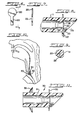
- Fig. 1 is a diagrammatic view showing a voice prosthesis device forming one embodiment of the invention inserted in a fistula communicating between the trachea and the esophagus of a laryngectomized patient.
- Fig. 2 is a side elevational view on enlarged scale of the voice prosthesis device shown in Fig. 1.
- Fig. 3 is an end elevational view taken on line 3-3 of Fig. 2.
- Fig. 4 is a fragmentary and elevational view corresponding to Fig. 3 on a substantially enlarged scale.
- Fig. 5 is a fragmentary longitudinal sectional view taken on line 5-5 of Fig. 4.
- Fig. 6 is an elevational view of a membrane-like flap or disc valve member forming a component of the voice prosthesis device shown in Figs. 1-5.
- Fig. 7 is an edge elevational view of the flap or disc taken on line 7-7 of Fig. 6.
- Fig. 8 is a longitudinal sectional view corresponding to Fig. 5 showing the membrane-like flap or disc valve member of Figs. 6 and 7 in place in the tubular housing before the flap or disc is cemented in place in the assembly operation.
- Fig. 9 is a fragmentary detail sectional view taken on line 9-9 of Fig. 8.
- Fig. 10 is a diagrammatic view similar to Fig. 1 and showing a second embodiment of the invention inserted in the fistula provided therefor in a laryngectomized patient.
- Fig. 11 is a longitudinal sectional view on enlarged scale through the prosthesis device shown in Fig. 10.
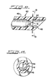
- Fig. 12 is a fragmentary longitudinal sectional view similar to Fig. 5 but showing the known manner in which the membrane-like flap or disc valve member was anchored or secured in place in the housing prior to the present invention.
- Fig. 13 is a sectional view taken on line 13-13 of Fig. 12 with the upper portion of the valve flap or disc being broken away.
- Referring to Fig. 1, the esophagus of the patient is indicated at 5 and the trachea at 6. The patient is provided with a surgical fistula communicating between the
trachea 6 and theesophagus 5 for reception of a voice prosthesis device designated at 10. This particular prosthesis device corresponds generally to one of two known types, namely, the so-called Blom-SingerT . M . prosthesis. Thedevice 10 has a tubular body or housing 11 which may be injection molded in known manner from a medical grade silicone material of known type. - The outer end of the
device 10 is exposed and retained in position by a pair of laterally-extending, skin-adhering tabs 12-12. Adjacent its inner end, the tubular housing or body 11 is provided with an integral retainingflange 13 which engages the front wall of the esophagus as shown in Fig. 1. - Referring particularly to Figs. 2, 5 and 8, it will be seen that the bore extending through the tubular housing 11 has four different sections designated at 14, 15, 16 and 17. The
bore section 14 is the longest and extends from the outer end of the device inwardly to the frusto-conical transition section 15 which joinssection 14 to the shorter andsmaller diameter section 16. The inner end of thesection 16 joins thebore section 17 adjacent the inner end of the device at a circumferential radial shoulder 18 (Figs. 5 and 8). This shoulder serves as a valve seat for a membrane-like flap ordisc 20 which forms the moving part of a one-way check valve. The flap ordisc 20 is flexible and formed of a water-resistant material such as silicone rubber or similar materials. - While the tubular body or housing 11 and the valve flap or
disc 20 are circular in cross-section and shape, respectively, it will be understood that they may be oval in cross-section and shape. - The tubular body 11 has an elongated
air inlet port 21 in the underside which provides communication between thetrachea 6 and thebore 14. It will be seen that the outer end of thebore section 17 constitutes an air outlet port which opens into the esophagus. The one-way check valve provided by the membrane-like flap ordisc 20 and thevalve seat 18 serves to allow air to be channeled from thetrachea 6 into theesophagus 5 during speaking, and, at other times, to close off communication between the esophagus and the trachea so as to prevent flow of esophageal contents (whether gaseous, liquid or solid) from the esophagus into the trachea. - The inner end of the tubular housing 11 is slanted, preferably at an angle of approximately 45°, so as to facilitate insertion of the
device 10 into the fistula provided therefor and to also provide an overhang orhood 19 that shields thebore section 17 from material passing downwardly through theesophagus 5. - The present invention is particularly concerned with the technique and manner in which the membrane-like valve flap or
disc 20 is anchored or secured in place in the housing 11. Referring to Figs. 6-9, it will be noted that the circular valve flap ordisc 20 has a tab- like extension orprojection 22 extending integrally therefrom. The housing or body 11 is provided with an outwardly diverging aperture 23 (Figs. 8 and 9) for receiving the tab orprojection 22. Theaperture 23 is most restricted at its inner or upper end whereat it has approximately the same dimensions as the cross-section of thetab 22, while allowing thetab 22 to be readily inserted downwardly therethrough. - Afcer the
valve flap 20 has been fully inserted into the body 11 with itsintegral projection 22 extending downwardly through theaperture 23, a drop of moisture- resistant cement 24 (Fig. 5) is deposited into the pocket or recess provided by theaperture 23, thereby securing and anchoring theprojection 22 firmly in place and sealing off theaperture 23. After thecement 24 has solidified, the projecting end portion of theprojection 22 is severed leaving the finished assembly as shown in Fig. 5. - It will be seen from Fig. 5 that the membrane-like valve flap or
disc 20 is normally seated against thevalve seat 18. However, when there is sufficient differential in pressure on opposite sides of the flap ordisc 20, as created in the wearer's act in speaking and producing a flow of air from thetrachea 6 toward theesophagus 5, the flap ordisc 20 will pivot or hinge at the integral connection or juncture between theprojection 22 and the periphery of the flap ordisc 20, thereby coming unseated and allowing air to flow through theprosthesis device 10 and enter theesophagus 5 for speaking. - The tubular housing or body 11 and the valve flap or
disc 20 can be produced on a production basis so as to meet appropriate specifications and tolerances. In other words, the exemplars of the bodies or housings 11 and thevalve members 20 produced on a quantity production basis will be substantially identical for all practical purposes. - It will be appreciated that the assembly of the membrane-like flaps or
discs 20 into the valve housings or bodies 11 is such that the resulting assemblies will be essentially identical. Furthermore, since the hinging or pivoting action of the circular flaps ordiscs 20 occurs at substantially identical locations and cross-sectional areas that are essentially identical from assembly to assembly, the resistance to airflow offered by the one-way check valves, and, in turn, theprosthesis devices 10 will be essentially uniform from exemplar to exemplar. - The actual resistance to airflow offered by the one-way check valve in any of the
voice prosthesis devices 10 made in accordance with this invention will depend on two factors. One is the area ant shape of the integral connection between the circular, oval (or otherwise shaped) valve flap ordisc 20 and itsprojection 22. The other factor is the nature of the particular material from which the valve flap ordisc 20 is formed. - In practice, it has been found that most laryngectomized patients are best served with a
voice prosthesis device 10 having a resistance to airflow which is approximately the same as that offered by a normal larynx. However, certain patients will need or prefer an airflow resistance somewhat lower and others an airflow resistance somewhat higher than that offered by the normal larynx. In production, these differences in uniform resistance to airflow can readily be obtained by variations in the modulus and hardness of the material from which the valve flaps ordiscs 20 and projections are formed. Thus, increased modulus and hardness result in decreases in resistance to airflow. - The present invention, as incorporated in the
voice prosthesis devices 10 of Figs. 1-9, may also be incorporated in the above-mentioned Panje implant-style of voice prosthesis. Such a second embodiment of the invention is shown in Figs. 10 and 11 wherein the voice prosthesis device is designated generally at 30. The housing orbody 31 of thedevice 30 is somewhat shorter than the body or housing 11 of thedevice 10, due to the fact that thedevice 30 needs only to span the surgical fistula between adjacent walls of the trachea and esophagus of the wearer with slight projections on opposite ends. While the inner end of thedevice 30, which resides in the esophagus, is provided with aretention flange 32 corresponding to theretention flange 13 of theprosthesis device 10, it is also provided with a frusto-conical shapedretention flange 33 instead of the retention flaps 12-12 of thedevice 10. Theflange 33 is preferably in the form of a Bellville washer for yielding engagement against the adjacent surface of the trachea. Except for the foregoing differences, thevoice prosthesis device 30 of the Panje type corresponds to thedevice 10 of Figs. 1-9. Furthermore, in respect to the present invention, thevoice prosthesis device 30, of Figs. 10 and 11, is identical with that of thevoice prosthesis device 10 of Figs. 1-9. - Prior to the present invention, the membrane-like flaps or discs of the one-way check valves in voice prosthesis devices of the tubular type represented by
devices 10 have been secured in place in the manner shown in thevoice prosthesis device 40 in Figs. 12 and 13. Referring to Figs. 12 and 13, a voice prosthesis device is indicated at 40 wherein a membrane-like flap ordisc 41 seats against a circumferential shoulder orvalve seat 42. The bore of thetubular body 43 is provided with an inwardly extendingradial projection 44 which acts to prevent the valve flap ordisc 41 from becoming accidentally unseated in the wrong direction. - As shown in Figs. 12 and 13, the flap or
disc 41 of the one-way check valve is anchored or attached to thevalve body 43 by a deposit ofcement 45 in accordance with known manner. In production, it is difficult to have each deposit ofcement 45 essentially identical in placement, amount, size and shape. Accordingly, there will be appreciable difference from assembly to assembly in respect to the location, size and shape of the arcuate cross-sectional area about which the valve flap ordisc 41 hinges or pivots. Consequently, there will be an appreciable variation in the resistance to airflow offered by thevoice prosthesis devices 40 when produced in production quantities. As explained above, the manner or attachment of the membrane-like flaps or discs of the one-way check valves provided by the present invention eliminates such variations and differences in resistance to airflow. - It will be understood certain changes and modifications can be made in the
voice prosthesis devices
Claims (6)
Priority Applications (1)
| Application Number | Priority Date | Filing Date | Title |
|---|---|---|---|
| AT84304445T ATE30377T1 (en) | 1983-06-30 | 1984-06-29 | VOICE PROSTHETATION INSTALLATION. |
Applications Claiming Priority (2)
| Application Number | Priority Date | Filing Date | Title |
|---|---|---|---|
| US06/509,963 US4610691A (en) | 1983-06-30 | 1983-06-30 | Voice prosthesis device |
| US509963 | 1983-06-30 |
Publications (2)
| Publication Number | Publication Date |
|---|---|
| EP0132957A1 true EP0132957A1 (en) | 1985-02-13 |
| EP0132957B1 EP0132957B1 (en) | 1987-10-28 |
Family
ID=24028810
Family Applications (1)
| Application Number | Title | Priority Date | Filing Date |
|---|---|---|---|
| EP84304445A Expired EP0132957B1 (en) | 1983-06-30 | 1984-06-29 | Voice prosthesis device |
Country Status (6)
| Country | Link |
|---|---|
| US (1) | US4610691A (en) |
| EP (1) | EP0132957B1 (en) |
| JP (1) | JPS6053140A (en) |
| AT (1) | ATE30377T1 (en) |
| CA (1) | CA1219402A (en) |
| DE (1) | DE3466931D1 (en) |
Cited By (8)
| Publication number | Priority date | Publication date | Assignee | Title |
|---|---|---|---|---|
| WO1986006970A3 (en) * | 1985-05-21 | 1987-04-23 | Walter Koss | Tracheotomy closure |
| US5107828A (en) * | 1985-05-21 | 1992-04-28 | Walter Koss | Tracheostoma closure device |
| WO1996014031A1 (en) * | 1994-11-04 | 1996-05-17 | Atos Medical Ab | Vocal prosthesis |
| DE202009001718U1 (en) | 2009-02-11 | 2009-04-16 | Neubauer, Norbert | voice prosthesis |
| DE202009002168U1 (en) | 2009-02-14 | 2009-04-23 | Neubauer, Norbert | voice prosthesis |
| DE202012003429U1 (en) | 2012-03-28 | 2012-05-16 | Norbert Neubauer | Introducer device for voice prosthesis |
| DE202012011837U1 (en) | 2012-12-11 | 2013-01-18 | Iskia Gmbh & Co.Kg | Voice prosthesis sleeve |
| DE202017002799U1 (en) | 2017-05-26 | 2017-07-21 | Norbert Neubauer | voice prosthesis |
Families Citing this family (13)
| Publication number | Priority date | Publication date | Assignee | Title |
|---|---|---|---|---|
| US4820304A (en) * | 1987-07-13 | 1989-04-11 | Bivona, Inc. | Speech prosthesis device |
| SE463649B (en) * | 1989-12-27 | 1991-01-07 | Atos Medical Ab | ROESTPROTES |
| US5391205A (en) * | 1991-12-17 | 1995-02-21 | Knight; Roy F. | Tracheoesophageal voice prosthesis |
| NL1000355C2 (en) * | 1995-05-12 | 1996-11-13 | Paul Ferdinand Schouwenburg | Voice prosthesis. |
| US5578083A (en) * | 1995-11-13 | 1996-11-26 | Helix Medical, Inc. | Voice prosthesis-cartridge assembly |
| US8317861B2 (en) * | 2001-04-11 | 2012-11-27 | Helix Medical, Llc | Antimicrobial indwelling voice prosthesis |
| US7520897B2 (en) * | 2001-04-11 | 2009-04-21 | Helix Medical, Llc | Medical devices having antimicrobial properties |
| NZ548505A (en) * | 2001-12-28 | 2007-12-21 | Helix Medical Llc | A flapper valve for a voice prosthesis |
| US7021314B1 (en) | 2004-07-19 | 2006-04-04 | Lane Charles J | Stoma stent with integrated speech flap valve |
| DE102004051679B3 (en) * | 2004-10-22 | 2005-12-22 | Bess Pro Gmbh | Prosthesis to be inserted between esophagus and trachea, comprising two membranes for avoidance of food or saliva entering trachea |
| US7998200B2 (en) * | 2005-06-06 | 2011-08-16 | Helix Medical, Llc | Voice prosthesis device |
| US20060287722A1 (en) * | 2005-06-17 | 2006-12-21 | Helix Medical Products, Inc. | Voice Prosthesis Device |
| DE202017005827U1 (en) | 2017-11-09 | 2017-11-29 | Norbert Neubauer | Sealing disc for voice prosthesis |
Citations (3)
| Publication number | Priority date | Publication date | Assignee | Title |
|---|---|---|---|---|
| US4040428A (en) * | 1976-08-30 | 1977-08-09 | The Aro Corporation | Control valves for tracheotomy patient or laryngeal prosthesis |
| EP0078685A1 (en) * | 1981-10-29 | 1983-05-11 | Hansa Medical Products Inc. | Apparatus for use in tracheotomy stoma |
| US4435853A (en) * | 1982-04-30 | 1984-03-13 | Hansa Medical Products, Inc. | Voice prosthesis device and placement tool therefor |
Family Cites Families (6)
| Publication number | Priority date | Publication date | Assignee | Title |
|---|---|---|---|---|
| US155667A (en) * | 1874-10-06 | Improvement in valves | ||
| US249557A (en) * | 1881-11-15 | truesdell | ||
| US2378613A (en) * | 1941-12-01 | 1945-06-19 | Arrowhead Rubber Company | Fuel tank flapper valve |
| US3628565A (en) * | 1970-03-03 | 1971-12-21 | Philco Ford Corp | Flexible check valves |
| US3957046A (en) * | 1974-11-27 | 1976-05-18 | Salvatore G. Militana | Disposable mouth to mouth resuscitation device |
| US4137117A (en) * | 1977-03-10 | 1979-01-30 | American Hospital Supply Corporation | Method of making a solvent-bonded joint |
-
1983
- 1983-06-30 US US06/509,963 patent/US4610691A/en not_active Expired - Lifetime
-
1984
- 1984-06-29 JP JP59134988A patent/JPS6053140A/en active Granted
- 1984-06-29 AT AT84304445T patent/ATE30377T1/en active
- 1984-06-29 EP EP84304445A patent/EP0132957B1/en not_active Expired
- 1984-06-29 DE DE8484304445T patent/DE3466931D1/en not_active Expired
- 1984-07-03 CA CA000458028A patent/CA1219402A/en not_active Expired
Patent Citations (3)
| Publication number | Priority date | Publication date | Assignee | Title |
|---|---|---|---|---|
| US4040428A (en) * | 1976-08-30 | 1977-08-09 | The Aro Corporation | Control valves for tracheotomy patient or laryngeal prosthesis |
| EP0078685A1 (en) * | 1981-10-29 | 1983-05-11 | Hansa Medical Products Inc. | Apparatus for use in tracheotomy stoma |
| US4435853A (en) * | 1982-04-30 | 1984-03-13 | Hansa Medical Products, Inc. | Voice prosthesis device and placement tool therefor |
Cited By (8)
| Publication number | Priority date | Publication date | Assignee | Title |
|---|---|---|---|---|
| WO1986006970A3 (en) * | 1985-05-21 | 1987-04-23 | Walter Koss | Tracheotomy closure |
| US5107828A (en) * | 1985-05-21 | 1992-04-28 | Walter Koss | Tracheostoma closure device |
| WO1996014031A1 (en) * | 1994-11-04 | 1996-05-17 | Atos Medical Ab | Vocal prosthesis |
| DE202009001718U1 (en) | 2009-02-11 | 2009-04-16 | Neubauer, Norbert | voice prosthesis |
| DE202009002168U1 (en) | 2009-02-14 | 2009-04-23 | Neubauer, Norbert | voice prosthesis |
| DE202012003429U1 (en) | 2012-03-28 | 2012-05-16 | Norbert Neubauer | Introducer device for voice prosthesis |
| DE202012011837U1 (en) | 2012-12-11 | 2013-01-18 | Iskia Gmbh & Co.Kg | Voice prosthesis sleeve |
| DE202017002799U1 (en) | 2017-05-26 | 2017-07-21 | Norbert Neubauer | voice prosthesis |
Also Published As
| Publication number | Publication date |
|---|---|
| DE3466931D1 (en) | 1987-12-03 |
| CA1219402A (en) | 1987-03-24 |
| JPH0429388B2 (en) | 1992-05-18 |
| ATE30377T1 (en) | 1987-11-15 |
| US4610691A (en) | 1986-09-09 |
| EP0132957B1 (en) | 1987-10-28 |
| JPS6053140A (en) | 1985-03-26 |
Similar Documents
| Publication | Publication Date | Title |
|---|---|---|
| EP0132957B1 (en) | Voice prosthesis device | |
| US4820304A (en) | Speech prosthesis device | |
| US6358222B1 (en) | Shunt valve | |
| US3852832A (en) | Prosthesis with fixation means | |
| EP0507832B1 (en) | Voice prosthesis | |
| US5080668A (en) | Cardiac valve prosthesis | |
| US5059208A (en) | Adjustable tracheostoma valve | |
| AU727888B2 (en) | Voice prosthesis-cartridge assembly | |
| US5107828A (en) | Tracheostoma closure device | |
| US5957978A (en) | Valved fenestrated tracheotomy tube | |
| US4614516A (en) | Voice prosthesis device | |
| US8377128B2 (en) | Flush patch for elastomeric implant shell | |
| JP3553955B2 (en) | Tracheal fistula device | |
| US4263682A (en) | Self-sealing valve and fluid fillable article including such a valve | |
| AU2002364225B2 (en) | Valve mounting assembly for voice prosthesis-cartridge and ring | |
| US5507809A (en) | Multi-valved voice prosthesis | |
| US7166128B1 (en) | Voice prosthesis | |
| CA2549612C (en) | Voice prosthesis device | |
| WO1986006970A2 (en) | Tracheotomy closure | |
| US5389088A (en) | Grommet | |
| US6254638B1 (en) | Voice prosthesis with biomedical sealing on the circumference | |
| WO1997026845A1 (en) | Method of manufacturing a voice prosthesis |
Legal Events
| Date | Code | Title | Description |
|---|---|---|---|
| PUAI | Public reference made under article 153(3) epc to a published international application that has entered the european phase |
Free format text: ORIGINAL CODE: 0009012 |
|
| AK | Designated contracting states |
Designated state(s): AT BE CH DE FR GB IT LI LU NL SE |
|
| 17P | Request for examination filed |
Effective date: 19850731 |
|
| RAP1 | Party data changed (applicant data changed or rights of an application transferred) |
Owner name: PURDUE RESEARCH FOUNDATION Owner name: BIVONA, INC. |
|
| 17Q | First examination report despatched |
Effective date: 19860616 |
|
| GRAA | (expected) grant |
Free format text: ORIGINAL CODE: 0009210 |
|
| ITF | It: translation for a ep patent filed | ||
| AK | Designated contracting states |
Kind code of ref document: B1 Designated state(s): AT BE CH DE FR GB IT LI LU NL SE |
|
| REF | Corresponds to: |
Ref document number: 30377 Country of ref document: AT Date of ref document: 19871115 Kind code of ref document: T |
|
| REF | Corresponds to: |
Ref document number: 3466931 Country of ref document: DE Date of ref document: 19871203 |
|
| ET | Fr: translation filed | ||
| PLBE | No opposition filed within time limit |
Free format text: ORIGINAL CODE: 0009261 |
|
| STAA | Information on the status of an ep patent application or granted ep patent |
Free format text: STATUS: NO OPPOSITION FILED WITHIN TIME LIMIT |
|
| 26N | No opposition filed | ||
| PGFP | Annual fee paid to national office [announced via postgrant information from national office to epo] |
Ref country code: GB Payment date: 19910619 Year of fee payment: 8 |
|
| PGFP | Annual fee paid to national office [announced via postgrant information from national office to epo] |
Ref country code: FR Payment date: 19910625 Year of fee payment: 8 |
|
| PGFP | Annual fee paid to national office [announced via postgrant information from national office to epo] |
Ref country code: SE Payment date: 19910627 Year of fee payment: 8 Ref country code: CH Payment date: 19910627 Year of fee payment: 8 |
|
| ITTA | It: last paid annual fee | ||
| PGFP | Annual fee paid to national office [announced via postgrant information from national office to epo] |
Ref country code: NL Payment date: 19910630 Year of fee payment: 8 Ref country code: AT Payment date: 19910630 Year of fee payment: 8 |
|
| PGFP | Annual fee paid to national office [announced via postgrant information from national office to epo] |
Ref country code: DE Payment date: 19910723 Year of fee payment: 8 |
|
| PGFP | Annual fee paid to national office [announced via postgrant information from national office to epo] |
Ref country code: LU Payment date: 19910806 Year of fee payment: 8 Ref country code: BE Payment date: 19910806 Year of fee payment: 8 |
|
| EPTA | Lu: last paid annual fee | ||
| PG25 | Lapsed in a contracting state [announced via postgrant information from national office to epo] |
Ref country code: LU Free format text: LAPSE BECAUSE OF NON-PAYMENT OF DUE FEES Effective date: 19920629 Ref country code: GB Effective date: 19920629 Ref country code: AT Effective date: 19920629 |
|
| PG25 | Lapsed in a contracting state [announced via postgrant information from national office to epo] |
Ref country code: SE Effective date: 19920630 Ref country code: LI Effective date: 19920630 Ref country code: CH Effective date: 19920630 Ref country code: BE Effective date: 19920630 |
|
| BERE | Be: lapsed |
Owner name: PURDUE RESEARCH FOUNDATION Effective date: 19920630 Owner name: BIVONA INC. Effective date: 19920630 |
|
| PG25 | Lapsed in a contracting state [announced via postgrant information from national office to epo] |
Ref country code: NL Effective date: 19930101 |
|
| NLV4 | Nl: lapsed or anulled due to non-payment of the annual fee | ||
| GBPC | Gb: european patent ceased through non-payment of renewal fee |
Effective date: 19920629 |
|
| PG25 | Lapsed in a contracting state [announced via postgrant information from national office to epo] |
Ref country code: FR Effective date: 19930226 |
|
| REG | Reference to a national code |
Ref country code: CH Ref legal event code: PL |
|
| PG25 | Lapsed in a contracting state [announced via postgrant information from national office to epo] |
Ref country code: DE Effective date: 19930302 |
|
| REG | Reference to a national code |
Ref country code: FR Ref legal event code: ST |
|
| EUG | Se: european patent has lapsed |
Ref document number: 84304445.4 Effective date: 19930109 |