EP0132325B1 - Fest verbundene Oberflächenbeläge - Google Patents
Fest verbundene Oberflächenbeläge Download PDFInfo
- Publication number
- EP0132325B1 EP0132325B1 EP84304424A EP84304424A EP0132325B1 EP 0132325 B1 EP0132325 B1 EP 0132325B1 EP 84304424 A EP84304424 A EP 84304424A EP 84304424 A EP84304424 A EP 84304424A EP 0132325 B1 EP0132325 B1 EP 0132325B1
- Authority
- EP
- European Patent Office
- Prior art keywords
- subsurface
- surface covering
- adhesive
- covering
- adhered
- Prior art date
- Legal status (The legal status is an assumption and is not a legal conclusion. Google has not performed a legal analysis and makes no representation as to the accuracy of the status listed.)
- Expired
Links
Images


Classifications
-
- D—TEXTILES; PAPER
- D06—TREATMENT OF TEXTILES OR THE LIKE; LAUNDERING; FLEXIBLE MATERIALS NOT OTHERWISE PROVIDED FOR
- D06N—WALL, FLOOR, OR LIKE COVERING MATERIALS, e.g. LINOLEUM, OILCLOTH, ARTIFICIAL LEATHER, ROOFING FELT, CONSISTING OF A FIBROUS WEB COATED WITH A LAYER OF MACROMOLECULAR MATERIAL; FLEXIBLE SHEET MATERIAL NOT OTHERWISE PROVIDED FOR
- D06N7/00—Flexible sheet materials not otherwise provided for, e.g. textile threads, filaments, yarns or tow, glued on macromolecular material
-
- E—FIXED CONSTRUCTIONS
- E04—BUILDING
- E04F—FINISHING WORK ON BUILDINGS, e.g. STAIRS, FLOORS
- E04F15/00—Flooring
- E04F15/18—Separately-laid insulating layers; Other additional insulating measures; Floating floors
-
- E—FIXED CONSTRUCTIONS
- E04—BUILDING
- E04F—FINISHING WORK ON BUILDINGS, e.g. STAIRS, FLOORS
- E04F15/00—Flooring
- E04F15/18—Separately-laid insulating layers; Other additional insulating measures; Floating floors
- E04F15/182—Underlayers coated with adhesive or mortar to receive the flooring
-
- E—FIXED CONSTRUCTIONS
- E04—BUILDING
- E04F—FINISHING WORK ON BUILDINGS, e.g. STAIRS, FLOORS
- E04F15/00—Flooring
- E04F15/18—Separately-laid insulating layers; Other additional insulating measures; Floating floors
- E04F15/186—Underlayers covered with a mesh or the like
-
- E—FIXED CONSTRUCTIONS
- E04—BUILDING
- E04F—FINISHING WORK ON BUILDINGS, e.g. STAIRS, FLOORS
- E04F15/00—Flooring
- E04F15/22—Resiliently-mounted floors, e.g. sprung floors
Definitions
- the present invention relates to adhered surface coverings, and more particularly to adhered surface coverings which will be suitable for use over stable or unstable subsurfaces.
- U.S. Patent No. 4,233,793 describes a method of bonding individual wooden floor members to a subfloor using an elastomeric cushioning adhesive of sufficient strength to overcome normal horizontal and vertical expansive buckling forces resulting from changes in the moisture content of the wooden floor members with atmospheric humidity changes.
- This patent is concerned with the problems occurring at the boundaries between the individual members as a result of their own shape change; it is not concerned with and provides no solution to the problems caused by dimensional changes in subsurfaces.
- the present application relates to processes for adhering surface coverings to subsurfaces using an adhesive whereby subsurface movement will not cause the adhesive bond to fail.
- one objective of the present invention is to provide a method by which a surface covering may be selected, and a suitable adhesive may be selected for use with the surface covering.
- the selection of the adhesive will depend on the dimensional stability of the subsurface and the performance characteristics of the surface covering.
- Another objective of the present invention is to provide methods by which products comprising one or more reinforcing layers may be modified in situ to provide buckling characteristics which allow the products to be used as adhered surface coverings in combination with appropriate adhesives.
- the present invention concerns surface coverings which are adhered to subsurfaces using an adhesive.
- a process is provided whereby an adhesive can be selected for use with an unmodified surface covering such that subsurface movement will not cause adhesive failure.
- Processes are also provided whereby modified surface coverings may be adhered using a similarly selected adhesive, or whereby adhesives may be selected and the surface coverings modified such that the adhesives will not fail due to subsurface movement.
- the present invention comprises a process for adhering a surface covering to a subsurface having an ascertainable subsurface dimensional change such that said surface covering will accommodate subsurface movement without buckling, said process comprising the steps of (a) selecting a surface covering, the critical buckle strain of the selected covering being less than the subsurface dimensional change; (b) selecting a target critical buckle strain which is greater than the subsurface dimensional change; (c) measuring the relaxed compressive stiffness, the bending stiffness, and the basis weight of said selected covering; (d) calculating the adhered basis weight for a surface covering having the measured bending stiffness, the measured relaxed compressive stiffness, and a critical buckle strain which is equal to the target critical buckle strain; (e) calculating the minimum adhesive strength which will be necessary to adhere said surface covering to said subsurface in a manner which will prevent buckling; (f) selecting a suitable adhesive, and (g) adhering said surface covering to said subsurface.
- the present invention comprises a process for modifying a surface covering comprising at least one reinforcing layer whereby it can be adhered without buckling to a subsurface having an ascertainable subsurface dimensional change, said process comprising the steps of (a) selecting a surface covering comprising at least one reinforcing layer, the critical buckle strain of said selected covering being less than the subsurface dimensional change; (b) selecting an adhesive having a determined adhesive strength; (c) measuring the basis weight, the bending stiffness and the relaxed compressive stiffness of said selected covering; (d) selecting a target critical buckle strain which is greater than the subfloor dimensional change; (e) calculating the adhered basis weight which would be obtained if said selected covering were adhered to said subsurface using said adhesive; (f) calculating the relaxed compressive stiffness for a modified surface covering having the measured bending stiffness, the calculated adhered basis weight, and a critical buckle strain which is equal to the target critical buckle strain, and (g) modifying said covering in situ such that it has a relaxed
- the present invention comprises a process for modifying a surface covering comprising at least one reinforcing layer, the modified covering being suitable to accommodate the subsurface movement of a subsurface having an ascertainable subsurface dimensional change when said modified covering is adhered to said subsurface, said process comprising the steps of (a) selecting a surface covering comprising at least one reinforcing layer, the critical buckle strain of said selected covering being less than the subsurface dimensional change; (b) modifying said covering in situ such that the critical buckle strain of the modified covering is greater than the initially measured critical buckle strain, but less than the critical buckle strain which would equal or exceed the subsurface dimensional change; (c) selecting a target critical buckle strain which is greater than the subsurface dimensional change; (d) measuring the bending stiffness, relaxed compressive stiffness and basis weight of said modified covering; (e) calculating the adhered basis weight for a covering having the measured bending stiffness, the measured relaxed compressive stiffness, and a critical buckle strain that is equal to the target critical buckle strain; and (f)
- the present invention relates to a surface covering which is suitable to be adhered with an adhesive to a subsurface without buckling, said surface covering comprising (a) a matrix material, and (b) at least one reinforcing layer disposed therein which has been modified in situ such that said surface covering has a critical buckle strain which is less than the subsurface dimensional change of said subsurface, the difference between said buckle strain and said subsurface dimensional change being such that the adhesive strength of a selected adhesive in combination with the basis weight of said surface covering will be sufficient to provide an adhesive bond having a strength which is not less than the adhered basis weight calculated for said surface covering.
- the present invention relates to a composite structure comprising a surface covering, a subsurface and an adhesive which adheres said surface covering and said subsurface together, said surface covering comprising (a) a matrix material, and (b) at least one reinforcing layer disposed therein which has been modified in situ, the critical buckle strain of said surface covering being less than the subsurface dimensional change of said subsurface, the difference between said critical buckle strain and said subsurface dimensional change being such that the adhesive strength of said adhesive in combination with the basis weight of said surface covering provides an adhesive bond having a strength which is not less than the adhered basis weight calculated for said surface covering.
- loose-lay floor structure is a floor structure which will lie flat on a stable or unstable subfloor, which will resist doming, curling, buckling, or movement under a rolling load, which preferably has a low structural stability value, and which need not be held in place using adhesives.
- accommodating surface covering is a surface covering which will accommodate or alter its size and shape to match that of an unstable subsurface, even when it is adhered to the subsurface.
- subsurface dimensional change is a measure of the change in length of a subsurface material under the conditions of its environment. This change is expressed herein as change per unit length.
- critical buckle strain is the strain at which a surface covering that is compressed in a planar fashion will buckle.
- adhered critical buckle strain is the strain at which a surface covering that is adhered to a subsurface with a given adhesive will buckle when compressed in a planar fashion.
- An adhered critical buckle strain value is usually applicable only to the surface covering/adhesive/subsurface system for which it is measured.
- relaxed compressive stiffness is the approximate compressing force per inch (centimeter) of width divided by the induced strain, the value of said relaxed compressive stiffness being projected to a 1000-hour load relaxation and the compressive force being applied in a planar fashion, the measurement being taken in the linear portion of the stress-strain curve.
- relaxed tensile stiffness is the approximate stretching force per inch (centimeter) of width divided by the induced strain, the value of said relaxed tensile -stiffness being projected to a 1000-hour load relaxation and the stretching force being applied in a planar fashion, the measurement being taken in the linear portion of the stress-strain curve.
- Basis weight is the weight in pounds per square yard (kilograms per square meter) of a surface covering material.
- adherered basis weight describes the calculated value which is the minimum strength necessary to adhere a surface covering to a subsurface. This value is a composite of the adhesive strength of an adhesive and the actual basis weight of a material, as will be explained in detail below.
- matrix material comprises all components of a surface covering material excluding the reinforcing material.
- bending stiffness is the resistance to bending demonstrated by a surface covering material as measured in inch-pounds (Newton-meters) using a cantilever beam or equivalent method, more especially that described in ASTM D747.
- bending resistance is a material parameter used in the theoretical derivation of the potential energy expression, and characterizes the resistance of the surface covering material to bending.
- structural stability is a measure of the change in length in percent of a surface covering sample which has been heated at 180°F (82.2°C) for six hours and reconditioned at 73.4°F (23°C) and 50% relative humidity for one hour.
- a surface covering should be expected to maintain within acceptable limits the shape and dimensions of the subsurface to which it is adhered, and it should not shrink leaving unsightly gaps. This requirement applies regardless of the nature of the subsurface. Therefore, a desirable trait for such a covering is that it have a structural stability under normal conditions of not more than 0.5% and preferably not more than 0.1%.
- the characteristics which must be demonstrated by the surface covering are less stringent than for an unstable subsurface since a minimal dimensional change of the surface covering results in minimal planar compressions of the surface covering. Nevertheless, problems can still be encountered which relate to doming, curling, and adhesive failure.
- the adhesive strength will be enhanced by the gravitational effect on the covering; if a ceiling covering is considered, the gravitational effect will detract from the adhesive strength; and if a wall covering is considered, the adhesive strength will be relatively unaffected because the gravitational pull will tend to shear in a direction perpendicular to the adhesive strength, a situation which may be ignored for purposes of the present invention.
- adhered basis weight is a composite of the adhesive strength of an adhesive and the actual basis weight of a surface covering
- adhered basis weight usually will be due almost entirely to the adhesive.
- a typical floor covering may have a basis weight of two to three pounds per square yard (1 to 2 Kg/m 2 )
- a typical adhesive may have an adhesive strength of two to three pounds per square inch (0.4 to 0.6 Kg/cm 2 ). Accordingly, in many instances the basis weight of the surface covering will be quite small in comparison to the adhesive strength.
- the adhered basis weight may be calculated by substituting appropriate values for relaxed compressive stiffness, bending stiffness, and target critical buckle strain into the standard equation, or it may be determined by adding the actual basis weight to, or substracting it from, the adhesive strength.
- Adhesives are often formulated for specific uses. Therefore, for purposes of the present invention, it is assumed that the artisan has the skill to select an adhesive which will show long-term compatibility with the surface covering, the subsurface, and the environment in which it is used. It must be emphasized, however, that the accurate determination of adhesive strength is very important and, for that reason, the directions for use provided by the manufacturer of the adhesive should be precisely followed.
- the application should be made in the same way for one test and for field installation; e.g., if the directions specify that an adhesive should be applied in a particular manner with a trowel having specified groove dimensions, the application of the adhesive should be performed exactly in that manner both for the test and when the surface covering is installed over a subsurface. If the installation is not performed in the same way, the predictions obtained according to the present invention may, in many instances, be invalid.
- the adhesive strength which should be used when practicing the present invention is the adhesive strength under load in a given environment. This value is defined as the approximate force per square unit of measure (inch 2 , yard 2 , centimeter 2 , or meter 2 ) at which the adhesive will fail. It preferably is calculated using the bending stiffness, relaxed compressive stiffness and actual basis weight of a given surface covering in combination with the adhered critical buckle strain, as previously defined.
- adhesive strength may be determined in. a number of different ways, the adhesive strength of an adhesive may be conveniently determined for a given surface covering/subsurface system by preparing test strips of surface coverings adhered to subsurface materials which have been conditioned at high relative humidity and temperature. When the adhered systems are subjected to drying conditions at low relative humidity, a strain is induced in the surface covering material. The tendency to buckle caused by the compressive strain which is introduced into the surface covering by subsurface shrinkage is usually compensated for by the adhesive; however, in many situations the adhesive eventually fails and the surface covering buckles. The strain at which this occurs is the adhered critical buckle strain of the system, and it is a measurable value. Consequently, it may be used to calculate the adhesive strength as illustrated in the examples. In appropriate circumstances, the adhesive strength value may also be projected mathematically or graphically from other adhesive strength data.
- rupture of the adhesive itself which is a loss of cohesive strength
- rupture of the bond between the adhesive and the test subsurface and rupture of the bond between the test surface backing and the adhesive.
- a determination of the type of rupture is not a feature of the present invention; however, it is information which is often useful to the artisan.
- the surface coverings are adhered to a subsurface with an adhesive
- several of the calculation limits suggested for loose-lay flooring no longer apply.
- floor tile and wall tile normally would not be rolled, and the suggested bending stiffness upper limit of ca 9 inch-pounds (1 Newton-meter) for loose-lay flooring would not be applicable to tile. Bending stiffness values in excess of 20 inch-pounds (2.3 Newton-meters) have been measured for flooring tiles; however, by extending the bending stiffness limits used in the calculations, suitable adhesive strengths have been determined. From this it will be apparent that the suggested ranges used in the calculations may be expanded as necessary to be compatible with the materials under consideration, and that the extensions of these ranges will not adversely affect the calculated results.
- n The potential energy, n, of a surface covering after buckling may be calculated as described in the parent application according to the formula:
- the bending resistance, C may be calculated from the bending stiffness measured according to the Olsen Stiffness Test, ANSI/ASTM D747, using the following equation where
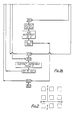
- the critical buckle strain may be calculated mathematically by applying the principle of minimum potential energy. Bending stiffness values, M W , are converted to bending resistance values, C. Upon setting the derivatives of n with respect to 8, and of 11 with respect to La, equal to zero, assigning values for E and Q, and varying C and K within known limits, (or, conversely, varying E and Q and assigning values to C and K), the equation may be solved. For example, this may be accomplished by using the Newton-Rathson Method of solving non-linear simultaneous equations. Flow charts for computer programs which may be used to effect these calculations are illustrated in Figs. 1A and 1B, and 3A and 3B.
- the critical buckle strain of the covering is then calculated in the usual manner. If the critical buckle strain is greater than the subsurface dimensional change, the situation falls within the scope of the loose-lay flooring situation- described in the parent application; i.e., no adhesive would be necessary unless the surface covering were to be used as a ceiling or a wall covering. However, if it is less than the subsurface dimensional change, the necessary minimum adhesive strength can be calculated. This may be done by selecting a target critical buckle strain in excess of the subsurface dimensional change; then, using this target value and the measured bending stiffness and relaxed compressive stiffness values, the adhered basis weight of the structure is calculated.
- the adhered basis weight is a value which incorporates two parameters, the actual basis weight of the surface covering and the minimum required adhesive strength of the adhesive.
- the structure is a ceiling tile
- the basis weight of the tile would act counter to the adhesive; thus, the minimum adhesive strength required for the adhesive would be the calculated adhered basis weight plus the actual basis weight.
- the structure is a floor structure
- the basis weight would act in concert with the adhesive; thus, the minimum adhesive strength would be the calculated adhered basis weight less the actual basis weight.
- the calculated adhesive strength is that which is necessary to minimally overcome the factors which would tend to cause the surface covering to separate from the subsurface. Accordingly, in this, as well as other situations, it may be advisable to select an adhesive having a greater-than-required adhesive strength so as to overcome unforeseen factors such as detrimental environmental effects, loss of strength due to plasticizer migration, and the like.
- the surface covering and the adhesive are selected, and the adhesive strength is determined as previously described.
- the bending stiffness, basis weight and relaxed compressive stiffness are measured for the unmodified surface covering, and an appropriate target critical buckle strain, in excess of the subsurface dimensional change, is selected.
- the adhered basis weight is determined depending on the intended use by combining the basis weight and the strength of the adhesive in an appropriate manner, as referred to above.
- the desired relaxed compressive stiffness can then be calculated using these data. From this information, the surface covering is modified in situ to give, ideally, a structure having the calculated relaxed compressive stiffness. Information relating to in situ modification was previously described in the parent application. Of course, safety factors may be included in these calculations, as previously suggested.
- the third hypothetical situation set forth above relates to a comparable situation, except that the modification is achieved first and then the minimum adhesive strength is determined by making the necessary calculations.
- the in situ modifications may be performed in a variety of ways. For example, modification may be performed on intact coverings or on partially constructed coverings which are later converted to surface' coverings having defined characteristics. Based on practical performance criteria, it appears to be preferred to modify the structure and then apply the back coat because the back coat usually seals the structure. This is especially true where seepage into an open structure might occur. Of course, the required degree of modification may also be determined by estimating the characteristics of individual components or combinations of individual components, or it may be achieved by evaluating composite structures and then back-calculating the characteristics which will be needed in future structures. As used herein, the term "in situ modification" means modification of a surface covering by changing the structure of its reinforcement when the latter is already in place in an at least partly formed covering.
- a continuous pattern of modification is one in which there is still a continuum of reinforcing material in the structure.
- a modified continuous pattern is one in which though there is a continuum the linear nature of its pattern is disrupted, while a discontinuous pattern is one in which there is no continuum of reinforcement.
- the reader is referred to Figs. 13 and 14 of the parent application for illustrations. Combinations of continuous, modified continuous and discontinuous patterns are also possible.
- the present invention has the advantage of providing a relatively reliable way to predict the characteristics of adhered surface coverings, and it also provides guidelines by which the various parameters may be modified so as to predictably alter the characteristics of such surface coverings.
- This example illustrates a process for adhering a surface covering to a substrate wherein the surface covering is unmodified and the adhesive is evaluated according to the present invention to ensure that it has adequate adhesive strength.
- plastisol compositions were prepared having the formulations listed below.
- the molecular weights of the resins are determinable from the specific viscosities (in parentheses) which were measured according to ASTM D-1243.
- a surface covering was prepared as follows: A roll of #F7155 glass reinforcing material (mat), commercially available from Manville Corporation and having a basis weight of 55 grams per square meter, was used as a reinforcing layer. The glass reinforcing mat was passed through a knife coater where plastisol A was deposited so as to saturate the mat. The knife coater was adjusted to provide a gelled saturated glass layer having a thickness of 0.018 inch (0.46 mm). The structure was passed around a heated drum with the plastisol-coated surface contacting the drum face. As a result of this procedure, which was conducted at a drum temperature of 285°F (141°C), the plastisol was gelled.
- a layer of plastisol B 0.005 inch (0.13 mm) thick was applied to the smooth drum-finished surface by reverse roll coating and the coated mat was gelled by heating in an oven at 280°F (138°C). The structure was then fed through a rotogravure printer to deposit a decorative image on the surface of the gelled plastisol B.
- a clear layer of plastisol D was applied over the printed surface to provide a protective surface 0.010-inch (0.25 mm) thick.
- the coated structure was passed through a fusion oven preheated to 380°F (193°C) to: (1) fuse the plastisol layer D, (2) expand the gelled layer of foamable plastisol B to about three times its applied thickness, and (3) expand the gelled, saturated glass layer to about twice its gelled thickness. After exiting from the oven, the fused structure was mechanically embossed to create depressed areas of about 0.010 inch (0.25 mm) in depth into the decorated surface covering.
- the structure was then completed by applying about 0.008 inch (0.20 mm) of plastisol C to the back of the embossed surface covering the fusing the plastisol around a drum heated at 325°F (163°C) for approximately 15 to 20 seconds. Finally, the completed structure was cooled and fed to a windup device.
- the measured thicknesses of the various layers of the final structure were as follows:
- This material was intended for installation over a subsurface having a subsurface dimensional change of 0.003; accordingly, a target critical buckle strain of 0.0035 was selected for use in the calculation.
- the computer program previously used was modified to calculate the adhered basis weight, the general modification being illustrated in Figs. 3A and 3B.
- the upper basis weight limit was extended to about 150 pounds per square yard (81 Kg/m 2 ) from the value of 10 pounds per square yard (5 Kg/m 2 ) previously used for calculating loose-lay flooring parameters.
- the measured values for the relaxed compressive stiffness and the bending stiffness, and the desired target critical buckle strain of 0.0035 were substituted into the equation and the adhered basis weight was calculated to be 145.4 pounds per square yard (78.9 Kg /m 2 ).
- the actual basis weight of the material (2.7 pounds per square yard or 1.5 Kg/m 2 ) would assist in holding the surface covering to the subsurface. Accordingly, the minimum adhesive force necessary to adhere the surface covering to the subsurface was calculated by subtracting 2.7 pounds per yquare yard (1.5 Kg/m 2 ) from the calculated adhered basis weight of 145.4 pounds per square yard (78.9 Kg/m 2 ), giving a value of 142.7 pounds per square yard (77.4 Kg/m 2 ). It is noted that if the surface covering had been intended for use as a ceiling tile, the basis weight would have detracted from the adhesive strength and the minimum adhesive strength would have been obtained by adding the actual basis weight to the adhered basis weight.
- Adhesives would normally be selected for long-term use in a given environment; therefore, in addition to strength, they would also be selected on the basis of their long-term compatibility with the particle board and with the fused PVC backcoat which were used to construct the surface covering/subsurface system. When considered on that basis, the three adhesive candidates normally would not have been selected because their long-term compatibility with these materials is unsatisfactory. However, because the purpose of this example was to illustrate the ability of the present invention to differentiate between adhesives on the basis of strength, and because the incompatibility problems were of little consequence during the term of the test, the incompatibility problems were disregarded.
- the selected adhesives were Armstrong's commercial adhesives S-750 and S-242, and an Armstrong experimental adhesive, referred to herein as EXP.
- the adhesive strength of each of these adhesives was measured in relation to the surface covering materials (the test vinyl backing and the test particle board subsurface) because no single adhesive strength value is applicable to an adhesive; i.e., the adhesive strength of an adhesive often varies depending on the materials with which it is used.
- the strain at failure is referred to as the adhered critical buckle strain, which was defined earlier.
- particle board sheets were conditioned in an environmental test chamber at 80% RH and 72°F (22.2°C) for four weeks, after which a 12 ft.x10 ft. (3.7 mx3.0 m) subsurface was built over a plywood support surface according to standard NPA installation directions. A 12 ft.x10 ft. (3.7 mx3.0 m) piece of surface covering was then adhered to the subsurface using the S-242 adhesive. It is emphasized that the adhesive was applied exactly as it was for the above-described strip test, and exactly according to the application directions.
- This example will illustrate the situation where an adhesive is selected and a selected surface covering is modified so that it will be suitable for use with the adhesive when adhered to a given subsurface.
- a surface covering was prepared essentially as described in Example 1, except that the glass mat was modified in situ after the embossing step, before the backing coat (plastisol C) was applied.
- This surface covering was selected for use over a particle board subsurface having a subsurface dimensional change of 0.0015.
- the EXP adhesive was selected and the adhesive strength of this adhesive was determined as described in Example 1 to be 13.0 pounds per square yard (7.1 Kg/m 2 ).
- the basis weight, bending stiffness and relaxed compressive stiffness were measured for the selected surface covering to give the following values: From these data, the unmodified surface covering was calculated to have a critical buckle strain of 0.0005. A target critical buckle strain of 0.002 was selected for use over the subsurface having an expected subsurface dimensional change of 0.0015.
- the surface covering in this example was also intended for use as a floor covering. Accordingly, the adhered basis weight was calculated by adding the adhesive strength of 13.0 pounds per square yard (7.1 Kg/m) for the adhesive and the actual basis weight (2.6 pounds per square yard or 1.4 Kg/m 2 ) of the surface covering, giving a value of 15.6 pounds per square yard (8.5 Kg/m2).
- the computer program illustrated in Figs. 1A and 1B was used to calculate the relaxed compressive stiffness, except that the upper limit for the basis weight was expanded such that it was in excess of the calculated adhered basis weight of 15.6 pounds per square yard (8.5 Kg/m 2 ).
- the measured bending stiffness, the adhered basis weight, and the target critical buckle strain were substituted into the equation to provide a calculated relaxed compressive stiffness value of 648 ppiow (113,500 N/m). Accordingly, modification of the surface covering was required in order to reduce the relaxed compressive stiffness from the initially measured value of 1,274 ppiow (223,100 N/m) to a value less than or equal to 648 ppiow (113,500 N/m).
- the surface covering was modified by cutting 1-inch (2.5 cm) diamond-shaped elements into the reinforcing layer from the back of the surface covering.
- the partial structure was fed upside down at room temperature through a pair of pinch rolls, the upper roll being an embossing roll especially designed to perforate the glass reinforcement and the lower roll being a smooth steel back-up roll.
- the roll pressure was adjustable such that modification could be varied from slight modification at low pressure to substantial modification at higher pressure. For purposes of the present test, the nip pressure was adjusted to 120 pounds per lineal inch (21.4 Kg/cm).
- the upper embossing roll was designed with a pattern comparable to that shown in Fig. 2; however, the pattern was angled at 45 degrees to the machine direction to create a diamond-shaped element pattern.
- the raised portions of the embossing roll were 0.045 inch (1.14 mm) high and 0.025 inch (0.64 mm) wide.
- the surface covering was installed over the selected particle board subsurface in the manner described in Example 1 and the adhered system was subjected to a six-week cycle during which the particle board shrank by about a factor of 0.0015, the expected subfloor dimensional change value.
- the installation performed satisfactorily and there was no evidence of buckling.
- This example will illustrate the modification of a surface covering, followed by selection of an appropriate adhesive which is compatible with the characteristics of the modified covering.
- a surface covering was partially prepared, modified, and then completed as described in Example 2.
- the following physical properties were measured for the modified structure: Using these data, a critical buckle strain of 0.001 was obtained for the in situ modified structure.
- a target critical buckle strain of 0.0035 was selected for use in the calculation based on a proposed particle board subfloor having a subfloor dimensional change of 0.003.
- the modified computer program illustrated in Figs. 3A and 3B was used to calculate the adhered basis weight by inserting the measured relaxed compressive stiffness and bending stiffness values, and the target critical buckle strain of 0.0035, into the equation.
- the adhered basis weight was calculated to be 35.8 pounds per square yard (19.4 Kg/m 2 ).
- This surface covering was also intended for use as a floor covering. Accordingly, the measured basis weight of 2.6 pounds per square yard (1.4 Kg/m 2 ) was subtracted from the calculated adhered basis weight of 35.8 pounds per square yard (19.4 Kg/m 2 ) in order to give a required minimum adhesive strength of 33.2 pounds per square yard (18.0 Kg/m 2 ) for the adhesive.
- a 10 ft.x12 ft. (3.0 mx3.7 m) surface covering sample was adhered to a particle board subsurface using the S-750 adhesive and tested as described above for six weeks under simulated environmental test conditions which would induce a subfloor dimensional change of 0.003. Satisfactory performance was found and there was no indication of buckling.
Landscapes
- Engineering & Computer Science (AREA)
- Architecture (AREA)
- Civil Engineering (AREA)
- Structural Engineering (AREA)
- Textile Engineering (AREA)
- Laminated Bodies (AREA)
- Adhesives Or Adhesive Processes (AREA)
- Synthetic Leather, Interior Materials Or Flexible Sheet Materials (AREA)
Claims (14)
Applications Claiming Priority (2)
| Application Number | Priority Date | Filing Date | Title |
|---|---|---|---|
| US50888483A | 1983-06-29 | 1983-06-29 | |
| US508884 | 1983-06-29 |
Publications (3)
| Publication Number | Publication Date |
|---|---|
| EP0132325A2 EP0132325A2 (de) | 1985-01-30 |
| EP0132325A3 EP0132325A3 (en) | 1986-04-23 |
| EP0132325B1 true EP0132325B1 (de) | 1988-11-23 |
Family
ID=24024466
Family Applications (1)
| Application Number | Title | Priority Date | Filing Date |
|---|---|---|---|
| EP84304424A Expired EP0132325B1 (de) | 1983-06-29 | 1984-06-28 | Fest verbundene Oberflächenbeläge |
Country Status (5)
| Country | Link |
|---|---|
| EP (1) | EP0132325B1 (de) |
| JP (1) | JPS6021983A (de) |
| AU (1) | AU561044B2 (de) |
| CA (1) | CA1253063A (de) |
| DE (1) | DE3475325D1 (de) |
Cited By (2)
| Publication number | Priority date | Publication date | Assignee | Title |
|---|---|---|---|---|
| DE19955713C1 (de) * | 1999-11-18 | 2001-07-05 | Johns Manville Int Inc | Wand- und Fußbodenbeläge |
| US7199065B1 (en) | 1999-07-30 | 2007-04-03 | Johns Manville | Non-woven laminate composite |
Family Cites Families (1)
| Publication number | Priority date | Publication date | Assignee | Title |
|---|---|---|---|---|
| US4233793A (en) * | 1975-07-07 | 1980-11-18 | Omholt Ray | Resiliently cushioned adhesive-applied wood flooring system and method of making the same |
-
1984
- 1984-03-13 CA CA000449492A patent/CA1253063A/en not_active Expired
- 1984-05-29 AU AU28788/84A patent/AU561044B2/en not_active Ceased
- 1984-06-27 JP JP59131229A patent/JPS6021983A/ja active Pending
- 1984-06-28 DE DE8484304424T patent/DE3475325D1/de not_active Expired
- 1984-06-28 EP EP84304424A patent/EP0132325B1/de not_active Expired
Cited By (3)
| Publication number | Priority date | Publication date | Assignee | Title |
|---|---|---|---|---|
| US7199065B1 (en) | 1999-07-30 | 2007-04-03 | Johns Manville | Non-woven laminate composite |
| US7351673B1 (en) | 1999-07-30 | 2008-04-01 | Johns Manville | Laminates including two or more layers of organic synthetic filament non-wovens and glass fiber webs and scrims |
| DE19955713C1 (de) * | 1999-11-18 | 2001-07-05 | Johns Manville Int Inc | Wand- und Fußbodenbeläge |
Also Published As
| Publication number | Publication date |
|---|---|
| EP0132325A2 (de) | 1985-01-30 |
| EP0132325A3 (en) | 1986-04-23 |
| AU561044B2 (en) | 1987-04-30 |
| CA1253063A (en) | 1989-04-25 |
| JPS6021983A (ja) | 1985-02-04 |
| DE3475325D1 (en) | 1988-12-29 |
| AU2878884A (en) | 1985-01-03 |
Similar Documents
| Publication | Publication Date | Title |
|---|---|---|
| US4654244A (en) | Loose-lay and adhered surface coverings | |
| US5501895A (en) | Floor covering underlayment | |
| US5578363A (en) | Floor covering underlayment | |
| US5268228A (en) | Grooved pressure-sensitive adhesive tape | |
| EP2809517B1 (de) | Für nasse oder feuchte bereiche geeignete vliesfaser | |
| EP3204551B1 (de) | Fasermatte und für nasse und feuchte bereiche geeignete gipsplatte | |
| US6722092B2 (en) | Paper bead | |
| KR20040093666A (ko) | 트러프-주연부를 갖는 건축용 패널 및 그 제조방법 | |
| US5080944A (en) | Hybrid floor covering | |
| USRE34357E (en) | Loose-lay and adhered surface coverings | |
| EP0132325B1 (de) | Fest verbundene Oberflächenbeläge | |
| US5082708A (en) | Tension floor covering with reinforcing layer | |
| Huang et al. | Creep of sandwich beams with polymer foam cores | |
| US5188874A (en) | Hybrid floor covering | |
| DK2644478T3 (en) | PLYWOOD PANEL | |
| EP0083220B1 (de) | Lose verlegter Bodenbelag | |
| Winistorfer et al. | Lateral and withdrawal strength of nail connections for manufactured housing | |
| JP2021147896A (ja) | 床用下貼りシート、床構造及び施工方法 | |
| CA1200068A (en) | Loose-lay flooring | |
| US4492606A (en) | Composite product having a low-porosity support layer, and method of manufacture thereof | |
| JPS58117173A (ja) | 下張り床の上に敷く弾性ルーズ・レイ床張り構造物及びその製造方法 | |
| CA2873430C (en) | Methods for encapsulating a substrate and products produced from same | |
| EP3070232A1 (de) | Artikel und verfahren zur verlegung eines keramikkachelfussbodens | |
| US20190270915A1 (en) | Double-sided self-adhesive vapor barrier | |
| CA2133522A1 (en) | Floor covering underlayment |
Legal Events
| Date | Code | Title | Description |
|---|---|---|---|
| PUAI | Public reference made under article 153(3) epc to a published international application that has entered the european phase |
Free format text: ORIGINAL CODE: 0009012 |
|
| AK | Designated contracting states |
Designated state(s): BE DE FR GB LU NL |
|
| PUAL | Search report despatched |
Free format text: ORIGINAL CODE: 0009013 |
|
| AK | Designated contracting states |
Kind code of ref document: A3 Designated state(s): BE DE FR GB LU NL |
|
| 17P | Request for examination filed |
Effective date: 19861017 |
|
| 17Q | First examination report despatched |
Effective date: 19870421 |
|
| GRAA | (expected) grant |
Free format text: ORIGINAL CODE: 0009210 |
|
| AK | Designated contracting states |
Kind code of ref document: B1 Designated state(s): BE DE FR GB LU NL |
|
| REF | Corresponds to: |
Ref document number: 3475325 Country of ref document: DE Date of ref document: 19881229 |
|
| ET | Fr: translation filed | ||
| PLBE | No opposition filed within time limit |
Free format text: ORIGINAL CODE: 0009261 |
|
| STAA | Information on the status of an ep patent application or granted ep patent |
Free format text: STATUS: NO OPPOSITION FILED WITHIN TIME LIMIT |
|
| 26N | No opposition filed | ||
| PGFP | Annual fee paid to national office [announced via postgrant information from national office to epo] |
Ref country code: FR Payment date: 19940513 Year of fee payment: 11 |
|
| PGFP | Annual fee paid to national office [announced via postgrant information from national office to epo] |
Ref country code: BE Payment date: 19940519 Year of fee payment: 11 |
|
| PGFP | Annual fee paid to national office [announced via postgrant information from national office to epo] |
Ref country code: DE Payment date: 19940525 Year of fee payment: 11 |
|
| PGFP | Annual fee paid to national office [announced via postgrant information from national office to epo] |
Ref country code: LU Payment date: 19940531 Year of fee payment: 11 Ref country code: GB Payment date: 19940531 Year of fee payment: 11 |
|
| PGFP | Annual fee paid to national office [announced via postgrant information from national office to epo] |
Ref country code: NL Payment date: 19940630 Year of fee payment: 11 |
|
| EPTA | Lu: last paid annual fee | ||
| PG25 | Lapsed in a contracting state [announced via postgrant information from national office to epo] |
Ref country code: LU Free format text: LAPSE BECAUSE OF NON-PAYMENT OF DUE FEES Effective date: 19950628 Ref country code: GB Effective date: 19950628 |
|
| PG25 | Lapsed in a contracting state [announced via postgrant information from national office to epo] |
Ref country code: BE Effective date: 19950630 |
|
| BERE | Be: lapsed |
Owner name: ARMSTRONG WORLD INDUSTRIES INC. Effective date: 19950630 |
|
| PG25 | Lapsed in a contracting state [announced via postgrant information from national office to epo] |
Ref country code: NL Effective date: 19960101 |
|
| GBPC | Gb: european patent ceased through non-payment of renewal fee |
Effective date: 19950628 |
|
| PG25 | Lapsed in a contracting state [announced via postgrant information from national office to epo] |
Ref country code: FR Effective date: 19960229 |
|
| NLV4 | Nl: lapsed or anulled due to non-payment of the annual fee |
Effective date: 19960101 |
|
| PG25 | Lapsed in a contracting state [announced via postgrant information from national office to epo] |
Ref country code: DE Effective date: 19960301 |
|
| REG | Reference to a national code |
Ref country code: FR Ref legal event code: ST |