EP0132042A2 - Hydrodynamischer Kolbenring und Zylindereinheit - Google Patents
Hydrodynamischer Kolbenring und Zylindereinheit Download PDFInfo
- Publication number
- EP0132042A2 EP0132042A2 EP84303861A EP84303861A EP0132042A2 EP 0132042 A2 EP0132042 A2 EP 0132042A2 EP 84303861 A EP84303861 A EP 84303861A EP 84303861 A EP84303861 A EP 84303861A EP 0132042 A2 EP0132042 A2 EP 0132042A2
- Authority
- EP
- European Patent Office
- Prior art keywords
- ring
- piston
- cylinder wall
- oil
- cylinder
- Prior art date
- Legal status (The legal status is an assumption and is not a legal conclusion. Google has not performed a legal analysis and makes no representation as to the accuracy of the status listed.)
- Withdrawn
Links
Images


Classifications
-
- F—MECHANICAL ENGINEERING; LIGHTING; HEATING; WEAPONS; BLASTING
- F16—ENGINEERING ELEMENTS AND UNITS; GENERAL MEASURES FOR PRODUCING AND MAINTAINING EFFECTIVE FUNCTIONING OF MACHINES OR INSTALLATIONS; THERMAL INSULATION IN GENERAL
- F16J—PISTONS; CYLINDERS; SEALINGS
- F16J9/00—Piston-rings, e.g. non-metallic piston-rings, seats therefor; Ring sealings of similar construction
-
- F—MECHANICAL ENGINEERING; LIGHTING; HEATING; WEAPONS; BLASTING
- F16—ENGINEERING ELEMENTS AND UNITS; GENERAL MEASURES FOR PRODUCING AND MAINTAINING EFFECTIVE FUNCTIONING OF MACHINES OR INSTALLATIONS; THERMAL INSULATION IN GENERAL
- F16J—PISTONS; CYLINDERS; SEALINGS
- F16J1/00—Pistons; Trunk pistons; Plungers
- F16J1/08—Constructional features providing for lubrication
Definitions
- the flexible rings are mounted in circumferential compression with end-gap springs. This elastic arrangement permits the rings to follow cylinder bore out-of-round distortions as the piston moves.
- the ring pack is arranged with each ring crowned so that its interaction with the cylinder wall oil film is essentially cylinder on flat plate fluid mechanics.
- the combination of spring forces, gas actuating forces, and radii of crown curvature produces a situation where the bottom ring, called the oil control ring, is always fully flooded and the other rings are operated in a partially starved but fully hydrodynamic condition.
- the rings should have essentially zero wear and extremely low friction.
- the ring assembly does not have a conventional scraper. This allows fully flooded lubrication of the piston skirts. In the place in the piston where an oil scraper might ordinarily be is a groove functioning as an oil reservoir to assure that the cylinder wall and ring pack stay flooded.
- Figure 1 shows a central-sectional view perpendicular to the wrist pin of a specially cooled piston which mounts the flexible piston rings.
- Wrist pin 1 rides in wrist pin boss 2 which is integrally connected to piston crown 3.
- piston crown 3 On the sides of the piston crown are circumferential grooves 4, 5 and 6 in which are mounted circumferentially loaded flexible and hydrodynamic piston rings 10, 12 and 14.
- Rings 10 and 12 have a preferred cylindrical crown radius of curvature of the order of two (2) inches (50.8 mm). Since such a crown would be indistinguishable from a line in the drawing, the crown shown is exaggerated for clarity.
- Ring 14, which functions to ration oil flow to the rings 10 and 12 has a cylindrical crown radius of curvature which is substantially less than the crown radius of rings 10 and 12 (for example, 1/4 inch).
- Piston skirts 16 and 18 are designed to be flexible and to function as centrally pivoted pivoted plane sliders.
- Heat piped assembly 20 forms a very high conductance thermal connection between piston crown 3 and skirts 16 and 18.
- Heat piped assembly 20 consists of an evacuated metallic passage with about 2 - 3X of its internal volume filled with working fluid 21, which transfers heat by evaporation and condensation at relatively low pressures as the piston operates.
- Heat piped assembly 20 is adhesively bonded to piston crown 3 and skirts 16 and 18 with high thermal conductance (metal-filled) silicone rubber or like material 22.
- the function of heat pipe 20 is to hold the piston assembly nearly isothermal, and substantially reduce the heat transfer across the oil film of the hydrodynamic rings so as to maximize the viscosity of oil on which the piston rings ride.
- Figure 2 is a central-sectional view parallel to the wrist pin 1 showing the geometry of the oil reservoir groove 102 and showing a means of maintaining some oil in the piston ring grooves to float the rings so that they can conform elastically to cylinder wall distortions and maintain oil control as required.
- oil-feed holes 26 and 27 which feed oil into the piston ring grooves 4 and 5. It may be necessary to provide small ring-groove vents to the crank case to prevent excessive oil supply to the ring grooves, and these will be illustrated later.
- the fluctuating forces on the wrist pin generate strong fluctuating pressures in squeeze film mode in the wrist pin journal bearing area.
- Figure 3a illustrates a rope or flexible cable in tension around a cylinder, to illustrate the result that such a rope or cable, if the cable or rope is very flexible and if friction between rope and cylinder can be ignored, will produce a uniform inward radial force around the circumference of the cylinder.
- the force will be perpendicular to the surface at all points, and will vary inversely with the local radius of curvature of the shape that the rope is tied around if the "cylindrical" shape is not perfect.
- the ability of the piston rings and piston skirts to conform to the distortions of the cylinder wall and to the tiny geometrical variations required to maximize oil film pressure forces is analogous to that of the case of a rope around a cylinder.
- the piston rings are in circumferential compression.
- the rings are very flexible with respect to the deformations required of them.
- the relationship of a ring to the cylinder wall constrains buckling.
- the piston rings conform to very fine scales so as to produce outward forces perpendicular to the local cylinder surface and inversely proportional to the surface radius of curvature. Since the local radius of curvature of the cylinder wall varies very little, the rings put essentially uniform outward radial forces on the cylinder wall.
- Figure 3b is a schematic showing how a flexible ring in circumferential compression will conform to small deformations to establish local radial force balances about the circumference. This schematic illustrates the reason the rings can conform elastically to produce the extremely fine-scale geometrical adjustments required to equalize full-film oil thicknesses around the ring circumference and produce oil control.
- Piston ring 139 is shaped and sized so as to have a much smaller bending moment of inertia than is conventional for rings. Ring 139 is loaded at the end gap with an end-gap separating spring 140 which serves to put ring 139 in circumferential compression.
- ring 139 is contained in a perfectly shaped cylinder wall, and if friction between ring 139 and cylinder wall 141 (and between the ring and the groove) is negligible there will be a uniform radial outward force between the ring crown and the cylinder wall 141. If, on the other hand, cylinder wall 141 is not perfectly cylindrical, and ring 139 is initially round, there will be sections of the spring with excessive radial force and other unsupported sections with no radial force.
- the ring will deform with respect to the distortions which occur on the cylinder wall or with respect to nonuniform forces produced by oil films so as to very closely (within plus or minus 5%) produce uniform outward radial forces around the circumference of the ring.
- the ring is flexible enough to accommodate cylinder out-of-round (which may amount to about 10 -3 of the cylinder bore diameter) and can accommodate variations in bore out-of-round as the piston reciprocates axially. If the ring is floating in the grooves so that the rings are free to move radially, the rings can produce force balances requiring extremely fine and rapid radial adjustments.
- the fully free ring of the present invention can move to balance local oil film forces between the ring crown and the cylinder all around the ring circumference. This fine scale conformance is required for oil control and full film lubrication of the rings.
- the fluid mechanics of the ring crown sliding against the cylinder with an oil film is such that change of a few microinches in clearance between ring crown and cylinder may produce a significant variation in oil film forces on the ring crown.
- the flexible ring is designed to very rapidly locally equilibrate these forces, increasing film thicknesses (and hence, reducing film pressures) when oil film pressures are excessive, and conversely thinning oil films (and increasing pressures) to achieve balance if the oil film pressure is too small.
- the geometrical accommodation between the ring crown and the cylinder wall to produce proper equilibration of the oil film forces requires extreme precision of the elastic characteristics of the ring. Oil film thicknesses between ring crown and cylinder wall may be as small as ten microinches. If the ring is free on an oil film in the grooves so that it can move radially with zero static friction this extreme precision of adjustment can be achieved, both on the average and at all points.
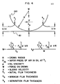
- Figure 4 is a schematic of a cylinder sliding on a flat plate to illustrate the fluid mechanics relevant to the fully hydrodynamic elastically compliant piston ring crown sliding on the cylinder wall.
- the film thicknesses between the ring crown and cylinder wall are so thin that the cylinder wall curvature has a negligible effect on the fluid mechanics between ring crown and cylinder wall.
- This cylinder 160 with radius R slides on flat plate 161 and moves to the left at a velocity U.
- An oil film thickness h + ⁇ covers the plate well ahead of the cylinder. Oil accumulated by the sliding cylinder forms maximum upstream film thickness h i .
- the hydrodynamic fluid motions between cylinder and plate generate pressures as the film converges from h i to minimum film thickness h oe After the film moves past minimum film thickness h o there is a divergence between cylinder and flat plate.
- the oil film slows down and separates in this divergent section.
- the film separates from the cylinder at a thickness h s and lays down a film of thickness h - ⁇ behind the sliding cylinder.
- Minimum film thickness h o near top and bottom dead center may be of the order of 10 microinches.
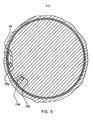
- Figure 5 shows a sectional view on A-A of Figure 1 showing the flexible ring 10 with end-gap loading via a spring 170 in line with the wrist pin.
- the second ring, ring 12 would have its end-gap and spring also in line with the wrist pin, but rotated 180°, and the oil control ring, ring 14, would have its end-gap spring in line with the end-gap of the ring 10 shown in Figure 5. Since there is a small supply of oil to the ring grooves from the wrist pin, in the manner illustrated in Figure 2, the ring grooves will float freely in squeeze film mode as the piston operates. This squeeze film situation occurs because there will be load reversal with respect to the grooves of the piston ring on every full cycle of the engine operation.
- FIG 5 also shows an oil drain passage 174 and a pressure driven oil drain hole 175 which connects to the crankcase pressure at the bottom of the piston.
- This drain arrangement is necessary to keep oil feed passage 27 shown in Figure 2 from overflooding the piston grooves.
- a similar drain arrangement rotated 180° is provided for the piston groove which mounts ring 12 (not shown).
- Figure 6 shows an enlarged cross-sectional view of the ring of Figure 8. It is required that the ring moment of inertia in bending be much less than that of typical rings.
- the ring may be scaled with the distance X shown in Figure 6 equal to .1 inches (2.54 mm) with the other dimensions roughly proportional to those in the drawing.
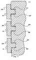
- FIG 7 is an enlarged cross-sectional view of the three- ring pack shown in Figure 1 illustrating more particularly the differences between the rings.
- rings 10 and 12 have a large (for example 2 inches) cylindrical crown radius of curvature (surfaces 210, 212) and the oil ring 14 has a cylindrical crown (surface 214) radius that is less than 1/4 the crown radius of rings 10 and 12.
- Ring 14 functions to ration oil to rings 10 and 12 for oil control, but must assure that a sufficiency of oil is supplied to assure that rings 10 and 12 function in the fully hydrodynamic but starved regime during intake and exhaust strokes for low friction and negligible wear.
- both the ring crown surfaces and the cylinder wall surface should be made as smooth as possible, preferably to an RMS value of a few microinches, so that the very thin oil films between ring crown and cylinder wall are not broken through by peaks and valleys in the surfaces. Even with great care it may, on occasion, happen that film breakdown between ring crowns and the cylinder walls occurs. This may happen particularly near top dead center piston position where gas actuating forces increase ring crown loads and where piston velocity vanishes on every cycle.
- the ring crowns must be cylindrical so that the geometry of the oil film between the cylinder wall and the crowns does not vary as the piston rocks.
- the finish on the ring crowns and cylinder walls must be as smooth as possible, since even the best oil films will be very thin.
- the rings must conform elastically to very fine scales to produce local and dynamic equilibration of the ring crown load and oil film forces all around the circumference of the ring. For this to be possible, it is necessary for a full film of oil to be established between the ring groove surfaces (211, 217, 213, 218, 215, 216) and the groove-engaging surfaces of the rings.
- oil flow past the ring is equal to h o U to within plus or minus 5%.
- h o is proportional to R. This means that if oil control ring 14 and compression rings 10 and 12 were to operate with the same loads W, the minimum film thickness of oil control ring 14 would be smaller than those of rings 10 and 12.
- the small radius of curvature oil control ring assures that rings 10 and 12 operate in a fully hydrodynamic, but somewhat "starved" condition most of the time. This is required for oil control.
- the equilibrium film thickness and load W of an oil film is a function not only of geometry, but also of the pressures above and below the ring crown.
- the oil film on the cylinder wall rapidly reaches partial pressure equilibrium with the air or products of combustion which surround the oil film. This means that the partial pressure of air or other gases above the compression ring is consistantly greater than the partial gas pressure in the oil film below the compression ring.
- Figure 8a is a top view of the cylinder showing blowdown grooves which may be used to assist oil control.
- Figure 8b is a centerline cutaway view of the cylinder wall further illustrating the blowdown grooves. All of the blowdown grooves can be simutaneously cut into the cylinder with a single tool in production with tightly controlled groove depth. It is desirable to have several hundred blowdown grooves evenly spaced circumferentially around the top of the cylinder wall. These blowdown grooves act as leakage paths between 10° before top dead center and 10° after top dead center for the top ring.
- the grooves should have a total circumference equal to approximately 1/4 of the cylinder circumference, and a depth of approximately .5 - 1 thousandths of an inch.
- the oil film thicknesses on the cylinder wall with the current invention rings will be much thicker than those of the current art rings, the film thicknesses will be sufficiently thin that no additional evaporation loss of oil is anticipated.
Landscapes
- Engineering & Computer Science (AREA)
- General Engineering & Computer Science (AREA)
- Mechanical Engineering (AREA)
- Chemical & Material Sciences (AREA)
- Combustion & Propulsion (AREA)
- Pistons, Piston Rings, And Cylinders (AREA)
- Support Of The Bearing (AREA)
Applications Claiming Priority (2)
| Application Number | Priority Date | Filing Date | Title |
|---|---|---|---|
| US06/502,578 US4470388A (en) | 1983-06-09 | 1983-06-09 | Fully hydrodynamic piston ring and cylinder assembly |
| US502578 | 1983-06-09 |
Publications (2)
| Publication Number | Publication Date |
|---|---|
| EP0132042A2 true EP0132042A2 (de) | 1985-01-23 |
| EP0132042A3 EP0132042A3 (de) | 1985-10-02 |
Family
ID=23998438
Family Applications (1)
| Application Number | Title | Priority Date | Filing Date |
|---|---|---|---|
| EP84303861A Withdrawn EP0132042A3 (de) | 1983-06-09 | 1984-06-07 | Hydrodynamischer Kolbenring und Zylindereinheit |
Country Status (4)
| Country | Link |
|---|---|
| US (1) | US4470388A (de) |
| EP (1) | EP0132042A3 (de) |
| JP (1) | JPS6045755A (de) |
| BR (1) | BR8402794A (de) |
Families Citing this family (7)
| Publication number | Priority date | Publication date | Assignee | Title |
|---|---|---|---|---|
| US4540185A (en) * | 1984-06-13 | 1985-09-10 | Hoult David P | Gas-lubricated seal for sealing between a piston and a cylinder wall |
| JPS62158142U (de) * | 1986-03-31 | 1987-10-07 | ||
| FR2602827B1 (fr) * | 1986-08-18 | 1988-11-04 | Melchior Jean | Piston pour machines alternatives a compression de fluide gazeux et machines equipees de tels pistons |
| US4809991A (en) * | 1988-03-07 | 1989-03-07 | Blatt John A | High-pressure resistant piston seal |
| US5085185A (en) * | 1990-09-14 | 1992-02-04 | Mechanical Technology, Incorporated | Powder-lubricant piston ring for diesel engines |
| JPH0571057U (ja) * | 1991-04-21 | 1993-09-24 | 正輝 白崎 | 表示板付きドア |
| US8844935B2 (en) * | 2011-04-13 | 2014-09-30 | Gamesa Innovation & Technology, S.L. | Seal arrangement |
Family Cites Families (6)
| Publication number | Priority date | Publication date | Assignee | Title |
|---|---|---|---|---|
| US2500295A (en) * | 1946-03-22 | 1950-03-14 | Allied Chem & Dye Corp | Pressure seal for rotary drum reactors |
| US3727927A (en) * | 1968-09-06 | 1973-04-17 | Int Harvester Co | Ring manufacture, productive of line contact seal |
| US4178899A (en) * | 1978-09-20 | 1979-12-18 | Harry Julich | Low-friction piston |
| US4318386A (en) * | 1979-09-20 | 1982-03-09 | Automotive Engine Associates | Vortex fuel air mixer |
| DE2849276C2 (de) * | 1978-11-14 | 1982-02-18 | Mahle Gmbh, 7000 Stuttgart | Ringnut eines Kolbens für mittelschnellaufende Verbrennungsmotoren |
| JPS593122Y2 (ja) * | 1979-08-09 | 1984-01-28 | 本田技研工業株式会社 | ピストンの給油装置 |
-
1983
- 1983-06-09 US US06/502,578 patent/US4470388A/en not_active Expired - Fee Related
-
1984
- 1984-06-07 EP EP84303861A patent/EP0132042A3/de not_active Withdrawn
- 1984-06-08 BR BR8402794A patent/BR8402794A/pt unknown
- 1984-06-09 JP JP59118983A patent/JPS6045755A/ja active Pending
Also Published As
| Publication number | Publication date |
|---|---|
| BR8402794A (pt) | 1985-05-21 |
| EP0132042A3 (de) | 1985-10-02 |
| US4470388A (en) | 1984-09-11 |
| JPS6045755A (ja) | 1985-03-12 |
Similar Documents
| Publication | Publication Date | Title |
|---|---|---|
| US4470375A (en) | Fully hydrodynamic piston ring and piston assembly with elastomerically conforming geometry and internal cooling | |
| EP0330326B1 (de) | Brennkraftmaschine ohne Öl-Schmierung, ohne Kühlung, mit gleichmässig zusammengepresster Gasfilm-Schmierung | |
| US4111104A (en) | Engine with low friction piston | |
| US4794848A (en) | Anti-seizing design for circumferentially continuous piston ring | |
| US7506575B2 (en) | Piston | |
| US7004119B2 (en) | Apparatus and method for rotating sleeve engine hydrodynamic seal | |
| US4470388A (en) | Fully hydrodynamic piston ring and cylinder assembly | |
| US4178899A (en) | Low-friction piston | |
| US7493850B2 (en) | Piston | |
| EP0071361A2 (de) | Kolben für eine Brennkraftmaschine | |
| JPS6237219B2 (de) | ||
| EP0204792A1 (de) | Kolben. | |
| JP2017198174A (ja) | 内燃機関 | |
| US4235447A (en) | Low friction oil control piston ring | |
| Sanda et al. | Analysis of lubrication of a piston ring package: Effect of oil starvation on oil film thickness | |
| US4724746A (en) | Tilting bearing pads for improved lubrication | |
| EP0069175A1 (de) | Kolben für eine Brennkraftmaschine mit innerer Verbrennung | |
| JPS6248950A (ja) | 自己密封ピストン | |
| JP6838296B2 (ja) | 内燃機関 | |
| Dowson et al. | Friction modelling for internal combustion engines | |
| EP1943444B1 (de) | Kolben | |
| GB2189005A (en) | Engines | |
| Mourelatos | Side-load capacity of an unlubricated ringless piston | |
| Xiaoming et al. | Numerical investigation of the EHL performance and friction heat transfer in piston and cylinder liner system | |
| Fritz et al. | BEARING LOAD ANALYSIS OF RECIPROCATING PISTON COMPRESSORS |
Legal Events
| Date | Code | Title | Description |
|---|---|---|---|
| PUAI | Public reference made under article 153(3) epc to a published international application that has entered the european phase |
Free format text: ORIGINAL CODE: 0009012 |
|
| AK | Designated contracting states |
Designated state(s): DE FR GB IT SE |
|
| PUAL | Search report despatched |
Free format text: ORIGINAL CODE: 0009013 |
|
| AK | Designated contracting states |
Designated state(s): DE FR GB IT SE |
|
| RHK1 | Main classification (correction) |
Ipc: F16J 9/00 |
|
| 17P | Request for examination filed |
Effective date: 19860523 |
|
| 17Q | First examination report despatched |
Effective date: 19870709 |
|
| STAA | Information on the status of an ep patent application or granted ep patent |
Free format text: STATUS: THE APPLICATION IS DEEMED TO BE WITHDRAWN |
|
| 18D | Application deemed to be withdrawn |
Effective date: 19871119 |
|
| RIN1 | Information on inventor provided before grant (corrected) |
Inventor name: SHOWALTER, MERLE ROBERT |