EP0132002B1 - Press for agricultural crop - Google Patents
Press for agricultural crop Download PDFInfo
- Publication number
- EP0132002B1 EP0132002B1 EP84200988A EP84200988A EP0132002B1 EP 0132002 B1 EP0132002 B1 EP 0132002B1 EP 84200988 A EP84200988 A EP 84200988A EP 84200988 A EP84200988 A EP 84200988A EP 0132002 B1 EP0132002 B1 EP 0132002B1
- Authority
- EP
- European Patent Office
- Prior art keywords
- baling
- outlet part
- pressing
- chamber
- baling chamber
- Prior art date
- Legal status (The legal status is an assumption and is not a legal conclusion. Google has not performed a legal analysis and makes no representation as to the accuracy of the status listed.)
- Expired
Links
- 230000002035 prolonged effect Effects 0.000 claims description 6
- 230000007704 transition Effects 0.000 claims description 2
- 230000006835 compression Effects 0.000 description 3
- 238000007906 compression Methods 0.000 description 3
- 230000015572 biosynthetic process Effects 0.000 description 2
- 239000011230 binding agent Substances 0.000 description 1
- 238000010276 construction Methods 0.000 description 1
- 230000008878 coupling Effects 0.000 description 1
- 238000010168 coupling process Methods 0.000 description 1
- 238000005859 coupling reaction Methods 0.000 description 1
- 239000000463 material Substances 0.000 description 1
- 230000003014 reinforcing effect Effects 0.000 description 1
- 238000011282 treatment Methods 0.000 description 1
Images


Classifications
-
- A—HUMAN NECESSITIES
- A01—AGRICULTURE; FORESTRY; ANIMAL HUSBANDRY; HUNTING; TRAPPING; FISHING
- A01F—PROCESSING OF HARVESTED PRODUCE; HAY OR STRAW PRESSES; DEVICES FOR STORING AGRICULTURAL OR HORTICULTURAL PRODUCE
- A01F15/00—Baling presses for straw, hay or the like
- A01F15/04—Plunger presses
- A01F15/044—Plunger presses with open pressing chambers
-
- A—HUMAN NECESSITIES
- A01—AGRICULTURE; FORESTRY; ANIMAL HUSBANDRY; HUNTING; TRAPPING; FISHING
- A01F—PROCESSING OF HARVESTED PRODUCE; HAY OR STRAW PRESSES; DEVICES FOR STORING AGRICULTURAL OR HORTICULTURAL PRODUCE
- A01F15/00—Baling presses for straw, hay or the like
- A01F15/04—Plunger presses
- A01F15/046—Plunger presses with press-boxes
Definitions
- the invention relates to a baling apparatus for baling agricultural crop comprising a frame, a baling chamber with an inlet port supported by said frame, a pressing member driven in a reciprocatory manner in the baling chamber, said baling chamber being provided with a plate-like member being pivotable about a shaft directed transversely of the pressing direction and acting in the closing position as a counter pressure member during the pressing of agricultural crop.
- Presses of the kind set forth in the preamble are known in many embodiments.
- a known embodiment, as disclosed in US-A-2593569 or DE-C-389716, is formed by the closed baling apparatus in which a rear wall is used against which the agricultural crop is compressed. In this case a high pressure can be attained already from the beginning so no loss occurs at the start.
- a disadvantage of this type of baling apparatus is that at the end of a pressing cycle the remainder is usually not sufficient to form a complete bale formed under high pressure. It is common practice to leave the remainder in the baling chamber for use during the next pressing cycle. The interval of time between the two cycles may be so long that the material in the baling chamber deteriorates to an extent such that it is no longer acceptable in wage services.
- baling apparatus in which a bale is formed at a previously formed bale.
- the previously formed bale serves as a counter-element for producing the desired pressure.
- This type of baling apparatus involves the problem that initially there is no bale capable of producing a sufficient counter-pressure. This is the more troublesome the higher becomes the nominal pressure. It may even last for five formed bales before the desired working pressure is reached. These initial bales are not suitable for the desired consecutive treatments.
- the invention has for its object to improve a device of the kind set forth in a manner such that the afore-said drawbacks will no longer occur.
- the device embodying the invention is distinguished in that the baling chamber is prolonged by an outlet part adapted to be cross-sectionally narrowed in the pressing direction, in that the pivot shaft of said removable plate-like member is located near the transition of the baling chamber and the outlet part, and in that the plate-like member constitutes in addition a part of the boundary of the outlet part, when said plate-like member is in the open position.
- the flap member it is now possible to produce a counter-pressure at the start so that even the first or second bale has sufficient density. After the formation of the first bale the flap member can be removed so that the first bale can then operate as a counter-pressure member in the narrowing outlet part of the press. The last amount of crop can be compressed by the desired high pressure and be removed from the baling chamber.
- the flap member is pivotable about a shaft directed transversely of the direction of compression so that after the formation of the first bale the flap member need only be turned away to release the passage.
- a lock bolt for the flap member on the boundary of the outlet part located opposite said shaft, by which bdtt the instant at which the member is to be turned away can be accurately fixed.
- the flap member constitutes in the passage- releasing position in addition the boundary of the outlet part so that the construction is appreciably simplified.
- the bottom boundary of the outlet part is pivotally connected with the baling chamber so that at the end of the pressing cycle the bales last formed can be removed in a simple manner.
- the flap member can be arranged opposite the bottom boundary in the top side of the prolonged outlet part so that the two boundary walls constitute the narrowing passage of the outlet part.
- the frame is provided with supporting wheels, whilst the frame is furthermore provided with pick-up means for picking up the crop from the field and feeding it into the baling chamber.
- a collecting space for temporarily storing the picked-up crop may be arranged between the pick-up means and the inlet port of the baling chamber.
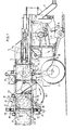
- the agricultural press shown in fig. 1 mainly comprises a frame 1 supported by ground wheels 2 and provided at the front with a coupling tree 3 for attachment to an agricultural tractor or the like.
- the frame On the top side the frame has a baling chamber 4, in which a pressing member formed by a plunqer5 can reciprocate.
- the plunger is driven by means of two hydraulic rams 6 arranged one on each side of the baling chamber 4.
- the baling chamber has an inlet port 7 on the bottom side.
- Below the baling chamber is suspended a collecting space or auxiliary chamber 8 for temporarily storing crop picked up from the field.
- the crop is picked up from the field by a pick-up device 9, which is pivotally fastened at 10 to the bottom edge of the auxiliary chamber 8. Behind the pick-up device 9 and in front of the beginning of the auxiliary chamber 8 pushing members 11 are rotatably journalled in the frame and movable along a substantially oval path 12.
- a flap 13 is rotatable about a shaft 14 through 360° in a manner such that the flap transfers the crop collected in the auxiliary chamber 8 through the inlet port 7 to the baling chamber 4.
- the flap 13 serves, in addition, for temporarily closing the inlet port 7.
- the press described above serves in particular to form high-density bales of agricultural crop, which type of press has been described earlier in, for example, GB-A-2025843.
- the mode of operation of this press is supposed to be known and lies beyond the scope of the invention.
- the press is now equipped with an outlet part generally designated by reference numeral 15.
- the outlet part is in line with the baling chamber 4 and comprises two fixed, vertical sidewalls 16 aligned to those of the baling chamber 4.
- the sidewalls 16 are reinforced by a vertical profile beam 17, said beams being interconnected at the top ends by a horizontal portal beam 18.
- a second portal beam 20, adapted to move freely up and down, is fastened to two or more pivotal arms 19, which can pivot up and down about a transverse shaft 32.
- cylinders 22 extending along the outer side of the sidewalls 16 are pivotally coupled at 21.
- the piston rod is pivotally coupled with the lower boundary 23 of the prolonged outlet part.
- the lower boundary 23 is rotatable about a pivotal shaft 24 directed transversely to the direction of compression and coupled with the baling chamber 4.
- the lower boundary 23 is reinforced by a profile beam 25.
- This profile beam 25 is provided on the rear side with a locking pin 26, around which a lock bolt 27 can be hooked.
- the look bolt 27 is pivotally fastened to the lower end of the vertical profile beam 17.
- the lower boundary is furthermore provided with a second lock bolt formed by a locking bar 28, which is pivotally fastened at 29 to the profile beam 25.
- the locking bar 28 can be moved up and down by means of a hydraulic ram 30 across the lower boundary 23 in order to lock a flap member to be described more fully hereinafter.
- the top boundary of the prolonged outlet part 15 is formed in this case by a wall part 31 which is pivotally connected at the transverse shaft 32 with the baling chamber 4.
- This wall part 31 can be turned downwards to an extent such that it can shut the passage at the transitional area between the baling chamber 4 and the outlet part 15.
- the edge of the flap member 31 remote from the pivotal shaft 32 is reinforced by a profile beam 33.
- the flap member 31 is in a vertical position in which it is blocked by means of the locking bar 28, which is lifted from the lower boundary 23 with the aid of the cylinder 30.
- the resultant bale can be tied up by means of any tying apparatus 34 formed in this case by a plurality of curved needles 24 adapted to pass through channels in the front side of the pressing member 5 for tying a binder, for example, twine around the bale by means of a knotting device 35.
- the tying/knotting device 34, 35 may be of an arbitrary design and lies beyond the scope of this invention.
- the locking bar 28 can be moved downwards by means of an inverse energization of the cylinder 30 until it is in the position shown in fig. 3.
- the flap member 31 is turned in clockwise direction about the pivotal shaft 32 in upward direction until the reinforcing profile beam 33 butts against the portal beam 20.
- the lower boundary member 23 is initially in the position shown in fig. 2, in which it is slightly lifted by the cylinders 22. Together with the flap member 31 in an intermediate position said boundary narrows the passage of the outlet part, whilst adequate counter-pressure is produced for obtaining the high pressure required for the subsequent bales.
- the bottom boundary 23 is pressed down and the end position is reached when the lock bolt 26 snaps into the hook 27, after which the flap member 31 is pressed further upwards whilst taking along the profile beam 20.
- the pressing cycle can continue until the agricultural crop is worked up and a residue is left in the baling chamber 4. This residue is compressed in the conventional manner by the high pressure and can finally be tied up in a small package. This final package, though smaller, yet has the same density as the preceding bales.
- the user can turn the locking hooks 27 in clockwise direction so that the lock bolt 26 is released. Then the bottom boundary can turn downwards about the shaft 24 in anti-clockwise direction, which can be furthered or braked respectively by the cylinders 22. The counter-pressure of the outlet part is thus eliminated so that the remaining bales can be readily removed along the sloping lower boundary.
- the flap member 31 may be designed in a manner differing from that shown, it being in particular conceivable to cause the member to turn about a vertical shaft so that the flap member can form part of the sidewall of the outlet part. It is furthermore possible to draw the flap member out of the baling chamber transversely of the direction of compression for releasing the passage.
- the flap member 31 may furthermore be formed by two or more movable parts.
Landscapes
- Life Sciences & Earth Sciences (AREA)
- Environmental Sciences (AREA)
- Storage Of Harvested Produce (AREA)
- Soil Working Implements (AREA)
- Basic Packing Technique (AREA)
- Processing Of Solid Wastes (AREA)
- Press Drives And Press Lines (AREA)
Description
- The invention relates to a baling apparatus for baling agricultural crop comprising a frame, a baling chamber with an inlet port supported by said frame, a pressing member driven in a reciprocatory manner in the baling chamber, said baling chamber being provided with a plate-like member being pivotable about a shaft directed transversely of the pressing direction and acting in the closing position as a counter pressure member during the pressing of agricultural crop.
- Presses of the kind set forth in the preamble are known in many embodiments. A known embodiment, as disclosed in US-A-2593569 or DE-C-389716, is formed by the closed baling apparatus in which a rear wall is used against which the agricultural crop is compressed. In this case a high pressure can be attained already from the beginning so no loss occurs at the start. A disadvantage of this type of baling apparatus, however, is that at the end of a pressing cycle the remainder is usually not sufficient to form a complete bale formed under high pressure. It is common practice to leave the remainder in the baling chamber for use during the next pressing cycle. The interval of time between the two cycles may be so long that the material in the baling chamber deteriorates to an extent such that it is no longer acceptable in wage services.
- A different type of baling apparatus, is the generally called channel baling apparatus, in which a bale is formed at a previously formed bale. The previously formed bale serves as a counter-element for producing the desired pressure. This type of baling apparatus involves the problem that initially there is no bale capable of producing a sufficient counter-pressure. This is the more troublesome the higher becomes the nominal pressure. It may even last for five formed bales before the desired working pressure is reached. These initial bales are not suitable for the desired consecutive treatments.
- The invention has for its object to improve a device of the kind set forth in a manner such that the afore-said drawbacks will no longer occur.
- The device embodying the invention is distinguished in that the baling chamber is prolonged by an outlet part adapted to be cross-sectionally narrowed in the pressing direction, in that the pivot shaft of said removable plate-like member is located near the transition of the baling chamber and the outlet part, and in that the plate-like member constitutes in addition a part of the boundary of the outlet part, when said plate-like member is in the open position.
- Thanks to the flap member it is now possible to produce a counter-pressure at the start so that even the first or second bale has sufficient density. After the formation of the first bale the flap member can be removed so that the first bale can then operate as a counter-pressure member in the narrowing outlet part of the press. The last amount of crop can be compressed by the desired high pressure and be removed from the baling chamber.
- In a preferred embodiment the flap member is pivotable about a shaft directed transversely of the direction of compression so that after the formation of the first bale the flap member need only be turned away to release the passage. According to a further aspect of the invention it is then advantageous to arrange a lock bolt for the flap member on the boundary of the outlet part located opposite said shaft, by which bdtt the instant at which the member is to be turned away can be accurately fixed.
- In a particularly advantageous embodiment the flap member constitutes in the passage- releasing position in addition the boundary of the outlet part so that the construction is appreciably simplified.
- In a further development of the invention the bottom boundary of the outlet part is pivotally connected with the baling chamber so that at the end of the pressing cycle the bales last formed can be removed in a simple manner.
- In accordance with a still further simplification of the device the flap member can be arranged opposite the bottom boundary in the top side of the prolonged outlet part so that the two boundary walls constitute the narrowing passage of the outlet part.
- For using the device on the field the frame is provided with supporting wheels, whilst the frame is furthermore provided with pick-up means for picking up the crop from the field and feeding it into the baling chamber.
- If required a collecting space for temporarily storing the picked-up crop may be arranged between the pick-up means and the inlet port of the baling chamber.
- In order to obtain the desired high pressures it is preferred to carry out by hydraulic agency the drive of the pressing member, the actuation of the flap member and the drive of the bottom boundary of the prolonged outlet part.
- The above-mentioned and further features of the invention will become apparent from the following description of the figures showing an embodiment.
- The drawing shows in
- fig. 1 a vertical sectional view of a mobile press for agricultural crop embodying the invention,
- figs. 2, 3 and 4 each a vertical sectional view of the outlet part of the press of fig. 1 in different working positions.
- The agricultural press shown in fig. 1 mainly comprises a frame 1 supported by
ground wheels 2 and provided at the front with a coupling tree 3 for attachment to an agricultural tractor or the like. On the top side the frame has a baling chamber 4, in which a pressing member formed by a plunqer5 can reciprocate. The plunger is driven by means of twohydraulic rams 6 arranged one on each side of the baling chamber 4. The baling chamber has an inlet port 7 on the bottom side. Below the baling chamber is suspended a collecting space or auxiliary chamber 8 for temporarily storing crop picked up from the field. The crop is picked up from the field by a pick-up device 9, which is pivotally fastened at 10 to the bottom edge of the auxiliary chamber 8. Behind the pick-up device 9 and in front of the beginning of the auxiliary chamber 8 pushing members 11 are rotatably journalled in the frame and movable along a substantiallyoval path 12. - In the auxiliary chamber 8 a
flap 13 is rotatable about ashaft 14 through 360° in a manner such that the flap transfers the crop collected in the auxiliary chamber 8 through the inlet port 7 to the baling chamber 4. Theflap 13 serves, in addition, for temporarily closing the inlet port 7. - The press described above serves in particular to form high-density bales of agricultural crop, which type of press has been described earlier in, for example, GB-A-2025843. The mode of operation of this press is supposed to be known and lies beyond the scope of the invention.
- According to the invention the press is now equipped with an outlet part generally designated by
reference numeral 15. The outlet part is in line with the baling chamber 4 and comprises two fixed,vertical sidewalls 16 aligned to those of the baling chamber 4. At the end thesidewalls 16 are reinforced by avertical profile beam 17, said beams being interconnected at the top ends by ahorizontal portal beam 18. - A
second portal beam 20, adapted to move freely up and down, is fastened to two or morepivotal arms 19, which can pivot up and down about atransverse shaft 32. At the other end of thesecond portal beam 20cylinders 22 extending along the outer side of thesidewalls 16 are pivotally coupled at 21. The piston rod is pivotally coupled with thelower boundary 23 of the prolonged outlet part. Thelower boundary 23 is rotatable about apivotal shaft 24 directed transversely to the direction of compression and coupled with the baling chamber 4. - Near the pivotal joint with the piston rod of the
cylinder 22 thelower boundary 23 is reinforced by aprofile beam 25. Thisprofile beam 25 is provided on the rear side with alocking pin 26, around which a lock bolt 27 can be hooked. The look bolt 27 is pivotally fastened to the lower end of thevertical profile beam 17. - The lower boundary is furthermore provided with a second lock bolt formed by a
locking bar 28, which is pivotally fastened at 29 to theprofile beam 25. Thelocking bar 28 can be moved up and down by means of ahydraulic ram 30 across thelower boundary 23 in order to lock a flap member to be described more fully hereinafter. - The top boundary of the prolonged
outlet part 15 is formed in this case by awall part 31 which is pivotally connected at thetransverse shaft 32 with the baling chamber 4. Thiswall part 31 can be turned downwards to an extent such that it can shut the passage at the transitional area between the baling chamber 4 and theoutlet part 15. The edge of theflap member 31 remote from thepivotal shaft 32 is reinforced by aprofile beam 33. - The operation of the device described above is set out in detail with reference to figs. 2, 3 and 4.
- Starting from the position shown in fig. 2 the
flap member 31 is in a vertical position in which it is blocked by means of thelocking bar 28, which is lifted from thelower boundary 23 with the aid of thecylinder 30. By feeding crop into the baling chamber 4 and by moving thepressing member 5 to the left an amount of crop can be compressed between theflap member 31 and thepressing member 5. This may occur in one or more pressing runs. The resultant bale can be tied up by means of anytying apparatus 34 formed in this case by a plurality ofcurved needles 24 adapted to pass through channels in the front side of thepressing member 5 for tying a binder, for example, twine around the bale by means of aknotting device 35. The tying/knotting device - After the first bale has been formed the
locking bar 28 can be moved downwards by means of an inverse energization of thecylinder 30 until it is in the position shown in fig. 3. By subsequently pressing further crop against the first bale theflap member 31 is turned in clockwise direction about thepivotal shaft 32 in upward direction until the reinforcingprofile beam 33 butts against theportal beam 20. - The
lower boundary member 23 is initially in the position shown in fig. 2, in which it is slightly lifted by thecylinders 22. Together with theflap member 31 in an intermediate position said boundary narrows the passage of the outlet part, whilst adequate counter-pressure is produced for obtaining the high pressure required for the subsequent bales. When the bales advance further thebottom boundary 23 is pressed down and the end position is reached when thelock bolt 26 snaps into the hook 27, after which theflap member 31 is pressed further upwards whilst taking along theprofile beam 20. - The pressing cycle can continue until the agricultural crop is worked up and a residue is left in the baling chamber 4. This residue is compressed in the conventional manner by the high pressure and can finally be tied up in a small package. This final package, though smaller, yet has the same density as the preceding bales.
- For emptying the outlet part the user can turn the locking hooks 27 in clockwise direction so that the
lock bolt 26 is released. Then the bottom boundary can turn downwards about theshaft 24 in anti-clockwise direction, which can be furthered or braked respectively by thecylinders 22. The counter-pressure of the outlet part is thus eliminated so that the remaining bales can be readily removed along the sloping lower boundary. - By inverting the energization of the
cylinders 22 thelower boundary 23 can be returned to the position shown in fig 2, in which the upper boundary formed by theflap member 31, which is freely rotatable about theshaft 32, is again moved into the vertical position and locked by means of the lockingbar 28. - Then the pressing cycle can be repeated.
- The invention is not limited to the embodiment described above. For example, the
flap member 31 may be designed in a manner differing from that shown, it being in particular conceivable to cause the member to turn about a vertical shaft so that the flap member can form part of the sidewall of the outlet part. It is furthermore possible to draw the flap member out of the baling chamber transversely of the direction of compression for releasing the passage. Theflap member 31 may furthermore be formed by two or more movable parts.
Claims (9)
Applications Claiming Priority (2)
| Application Number | Priority Date | Filing Date | Title |
|---|---|---|---|
| NL8302489A NL8302489A (en) | 1983-07-12 | 1983-07-12 | PRESS FOR AGRICULTURAL CROPS. |
| NL8302489 | 1983-07-12 |
Publications (3)
| Publication Number | Publication Date |
|---|---|
| EP0132002A2 EP0132002A2 (en) | 1985-01-23 |
| EP0132002A3 EP0132002A3 (en) | 1986-06-11 |
| EP0132002B1 true EP0132002B1 (en) | 1990-04-04 |
Family
ID=19842151
Family Applications (1)
| Application Number | Title | Priority Date | Filing Date |
|---|---|---|---|
| EP84200988A Expired EP0132002B1 (en) | 1983-07-12 | 1984-07-06 | Press for agricultural crop |
Country Status (8)
| Country | Link |
|---|---|
| US (1) | US4924667A (en) |
| EP (1) | EP0132002B1 (en) |
| JP (1) | JPS6041416A (en) |
| BR (1) | BR8403548A (en) |
| DE (1) | DE3481802D1 (en) |
| DK (1) | DK341084A (en) |
| ES (1) | ES534208A0 (en) |
| NL (1) | NL8302489A (en) |
Families Citing this family (4)
| Publication number | Priority date | Publication date | Assignee | Title |
|---|---|---|---|---|
| JPS62267681A (en) * | 1986-05-16 | 1987-11-20 | Murata Mfg Co Ltd | Measuring instrument for distribution of magnetic field |
| US5461975A (en) * | 1994-06-16 | 1995-10-31 | Driggs; Leland W. | Low friction baler liner |
| DE19928819A1 (en) * | 1999-06-17 | 2000-12-21 | Usines Claas France St Remy Wo | Baler |
| GB9916255D0 (en) * | 1999-07-12 | 1999-09-15 | Ford New Holland Nv | Apparatus and method for positioning steerable wheels |
Family Cites Families (12)
| Publication number | Priority date | Publication date | Assignee | Title |
|---|---|---|---|---|
| DE389716C (en) * | 1924-02-06 | Patentpressen G M B H Deutsche | Baler for short and long fiber fabrics | |
| DE289460C (en) * | ||||
| FR761436A (en) * | 1934-03-16 | |||
| US2593569A (en) * | 1949-02-15 | 1952-04-22 | Harold Gurinsky | Frame structure for hay balers |
| FR1029103A (en) * | 1950-12-05 | 1953-05-29 | A Blachere & Ses Fils Ets | Improvement in counterweight press doors |
| US3426672A (en) * | 1966-04-20 | 1969-02-11 | Sperry Rand Corp | Hay baler |
| US3808766A (en) * | 1972-10-06 | 1974-05-07 | Dundas | Machine for compacting and packaging waste material |
| US4044569A (en) * | 1976-04-15 | 1977-08-30 | Harza Richard D | Refuse disposal apparatus |
| US4037528A (en) * | 1976-08-27 | 1977-07-26 | Hesston Corporation | Density control mechanism for crop baler |
| NL189644C (en) * | 1978-11-03 | 1993-06-16 | Multinorm Bv | APPARATUS FOR BALING STILLY-LESS AGRICULTURAL CROP. |
| US4334466A (en) * | 1980-09-02 | 1982-06-15 | Spiegelberg Delvin A | High pressure hay rebaler |
| NL8103783A (en) * | 1981-08-12 | 1983-03-01 | Johannes Martinus Willibrordus | APPARATUS FOR COMPRESSING A MORE OR MORE LOSS RELATED MASS INTO A PACKAGE. |
-
1983
- 1983-07-12 NL NL8302489A patent/NL8302489A/en not_active Application Discontinuation
-
1984
- 1984-07-06 DE DE8484200988T patent/DE3481802D1/en not_active Expired - Fee Related
- 1984-07-06 EP EP84200988A patent/EP0132002B1/en not_active Expired
- 1984-07-10 US US06/629,439 patent/US4924667A/en not_active Expired - Fee Related
- 1984-07-11 DK DK341084A patent/DK341084A/en not_active Application Discontinuation
- 1984-07-11 ES ES534208A patent/ES534208A0/en active Granted
- 1984-07-12 JP JP59143388A patent/JPS6041416A/en active Pending
- 1984-07-12 BR BR8403548A patent/BR8403548A/en unknown
Also Published As
| Publication number | Publication date |
|---|---|
| BR8403548A (en) | 1985-06-25 |
| ES8504425A1 (en) | 1985-04-16 |
| US4924667A (en) | 1990-05-15 |
| ES534208A0 (en) | 1985-04-16 |
| NL8302489A (en) | 1985-02-01 |
| DE3481802D1 (en) | 1990-05-10 |
| EP0132002A3 (en) | 1986-06-11 |
| DK341084D0 (en) | 1984-07-11 |
| DK341084A (en) | 1985-01-13 |
| JPS6041416A (en) | 1985-03-05 |
| EP0132002A2 (en) | 1985-01-23 |
Similar Documents
| Publication | Publication Date | Title |
|---|---|---|
| EP1106054B1 (en) | A bale press | |
| US5247880A (en) | Horizontal baler with movable bottom support ejector | |
| US5735199A (en) | Four-side squeeze mechanism for extrusion-type square baler | |
| US4170934A (en) | Device for compressing crop into bales | |
| US8978550B2 (en) | In-line bale eject system | |
| CA2215238A1 (en) | Extrusion type square baler having selective bale ejector | |
| EP0974258B1 (en) | Bale discharge means for a rectangular baler | |
| US4193251A (en) | Baling device for agricultural crops | |
| EP0132002B1 (en) | Press for agricultural crop | |
| EP3563663B1 (en) | High density plunger movement | |
| US7007596B2 (en) | Bale press for loose material | |
| US4711078A (en) | Baler and process for making bales or for operating the baler | |
| US3469530A (en) | Rubbish baling apparatus | |
| US4715175A (en) | Binder-twine guide and cutter mechanism for roll-baler | |
| EP4026688A1 (en) | Baler and method for operating the same | |
| US4184426A (en) | Baling device for agricultural crops | |
| US5058495A (en) | Knotter trip mechanism with locking device | |
| GB1576154A (en) | Baler | |
| US6698343B2 (en) | Baling chamber having adjustable cross section | |
| US20040250708A1 (en) | Arrangement to support the ejection of a cylindrical bale | |
| EP0878293A1 (en) | A rotatable bale release mechanism for a baler machine and method of baling | |
| US4095520A (en) | Horizontal baler | |
| US6698339B2 (en) | Baling chamber having adjustable cross section | |
| GB1567177A (en) | Apparatus for compressing solid material | |
| AU2003200756B2 (en) | Large rectangular baler having hydraulically powered functions, and control system therefor |
Legal Events
| Date | Code | Title | Description |
|---|---|---|---|
| PUAI | Public reference made under article 153(3) epc to a published international application that has entered the european phase |
Free format text: ORIGINAL CODE: 0009012 |
|
| AK | Designated contracting states |
Designated state(s): DE FR GB NL |
|
| PUAL | Search report despatched |
Free format text: ORIGINAL CODE: 0009013 |
|
| AK | Designated contracting states |
Kind code of ref document: A3 Designated state(s): DE FR GB NL |
|
| 17P | Request for examination filed |
Effective date: 19861208 |
|
| 17Q | First examination report despatched |
Effective date: 19880212 |
|
| GRAA | (expected) grant |
Free format text: ORIGINAL CODE: 0009210 |
|
| AK | Designated contracting states |
Kind code of ref document: B1 Designated state(s): DE FR GB NL |
|
| REF | Corresponds to: |
Ref document number: 3481802 Country of ref document: DE Date of ref document: 19900510 |
|
| ET | Fr: translation filed | ||
| PLBE | No opposition filed within time limit |
Free format text: ORIGINAL CODE: 0009261 |
|
| STAA | Information on the status of an ep patent application or granted ep patent |
Free format text: STATUS: NO OPPOSITION FILED WITHIN TIME LIMIT |
|
| 26N | No opposition filed | ||
| PGFP | Annual fee paid to national office [announced via postgrant information from national office to epo] |
Ref country code: GB Payment date: 19920720 Year of fee payment: 9 |
|
| PGFP | Annual fee paid to national office [announced via postgrant information from national office to epo] |
Ref country code: FR Payment date: 19920728 Year of fee payment: 9 |
|
| PGFP | Annual fee paid to national office [announced via postgrant information from national office to epo] |
Ref country code: DE Payment date: 19920729 Year of fee payment: 9 |
|
| PGFP | Annual fee paid to national office [announced via postgrant information from national office to epo] |
Ref country code: NL Payment date: 19920731 Year of fee payment: 9 |
|
| PG25 | Lapsed in a contracting state [announced via postgrant information from national office to epo] |
Ref country code: GB Effective date: 19930706 |
|
| PG25 | Lapsed in a contracting state [announced via postgrant information from national office to epo] |
Ref country code: NL Effective date: 19940201 |
|
| GBPC | Gb: european patent ceased through non-payment of renewal fee |
Effective date: 19930706 |
|
| NLV4 | Nl: lapsed or anulled due to non-payment of the annual fee | ||
| PG25 | Lapsed in a contracting state [announced via postgrant information from national office to epo] |
Ref country code: FR Effective date: 19940331 |
|
| PG25 | Lapsed in a contracting state [announced via postgrant information from national office to epo] |
Ref country code: DE Effective date: 19940401 |
|
| REG | Reference to a national code |
Ref country code: FR Ref legal event code: ST |