EP0131777B1 - Yoke with automatic closure for animals - Google Patents
Yoke with automatic closure for animals Download PDFInfo
- Publication number
- EP0131777B1 EP0131777B1 EP84106999A EP84106999A EP0131777B1 EP 0131777 B1 EP0131777 B1 EP 0131777B1 EP 84106999 A EP84106999 A EP 84106999A EP 84106999 A EP84106999 A EP 84106999A EP 0131777 B1 EP0131777 B1 EP 0131777B1
- Authority
- EP
- European Patent Office
- Prior art keywords
- levers
- opening
- lever
- cable
- plane
- Prior art date
- Legal status (The legal status is an assumption and is not a legal conclusion. Google has not performed a legal analysis and makes no representation as to the accuracy of the status listed.)
- Expired
Links
Images


Classifications
-
- A—HUMAN NECESSITIES
- A01—AGRICULTURE; FORESTRY; ANIMAL HUSBANDRY; HUNTING; TRAPPING; FISHING
- A01K—ANIMAL HUSBANDRY; CARE OF BIRDS, FISHES, INSECTS; FISHING; REARING OR BREEDING ANIMALS, NOT OTHERWISE PROVIDED FOR; NEW BREEDS OF ANIMALS
- A01K1/00—Housing animals; Equipment therefor
- A01K1/06—Devices for fastening animals, e.g. halters, toggles, neck-bars or chain fastenings
- A01K1/062—Neck-bars, e.g. neck collars
Definitions
- the invention relates to a self-catching neck frame for larger animals, in particular cattle, with a support frame which can be suspended in an animal stall; with two two-armed opening levers lying in a substantially vertical plane, which are arranged symmetrically to a vertical plane which is perpendicular to the plane of the opening levers, and which at their upper ends are rotatably mounted on the supporting frame about axes which are parallel to the plane of symmetry and are essentially horizontal ; with two two-armed locking levers arranged in the plane of the opening levers symmetrically to the plane of symmetry, the upper ends of which are articulated to the lower ends of the opening levers and articulated at their lower ends, the articulation point (s) being connected to the floor of the barn by means of a flexible strand is / are; with a lock arranged on the support frame for reversibly locking the opening levers in their essentially vertical closed position and with a cable for unlocking the lock, which engages the knee of a knee lever, the arms of which are articulated at the
- the toggle arms (39) are of the same length and grips the pull cable (38) exactly on the knee of the toggle lever (39, 39). at.
- the opening levers are provided with a spring (spring 22 or compression spring 22a) which ensures maximum expansion during the opening and closing of the self-locking neck frame or compression, the exceeding of which brings about the closing or opening state of the frame, which is secured in the case of a single frame, for example, by a latch lock.
- a disadvantage of the known self-catching neck frame is that either a so-called group release, i.e. the simultaneous opening of several frames, is not possible, or that the single release, and even more so the group release, requires a relatively large amount of tractive effort, which has to be applied via the cable .
- the invention is therefore based on the object of providing a self-catching neck frame which not only ensures reliable self-catching of the animal, but also secure locking of the opening levers in their closed position and easy pivoting open of the same after unlocking, so that group triggering by hand is easily possible .
- the extension of the shorter toggle lever arm and the lower end of the curve piece when the frame is closed are rigidly connected by means of an arm which extends perpendicular to the extension.
- This arm represents a lever arm of considerable length, which facilitates the operation of the knee lever.
- the support frame for the pivot point of an opening lever has a horizontal row of essentially horizontal bores for optionally receiving a hinge pin, and bores arranged approximately symmetrically to the plane of symmetry are each occupied by a hinge pin, the horizontal distance of which determines the neck width of the closed frame .
- the support frame is provided with adjustable screw stops for the upper arms of the opening lever and for the connecting arm, so that when the self-catching neck frame according to the invention is closed, its knee lever knee and knee lever pivot points are relieved of strain, or that the same joints are not overloaded in the opening state if the animal is in front the frame lock throws its neck through the frame opening against one of the opening levers.
- the support frame has two cranked plates which are symmetrical with respect to the plane of the opening levers, the lower plates of which are closer to one another Parts include the opening levers at their pivot points, and their upper, spaced-apart parts include the toggle lever and the rope curve piece between them.
- the two locking levers of which are attached at their lower ends to the upper ends of a U-shaped bracket, the yoke of which is connected to the floor of the barn by means of the flexible strand, the upper ends of the bracket which are articulated to the locking levers are each one formed essentially vertical connector, which is attached to the outside of each bracket leg and is dimensioned in length so that the lower ends of the locking lever in their substantially vertical closed position connect almost seamlessly to the upper ends of the bracket legs.
- the two locking levers are articulated at their lower ends by means of a pivot, the axis of which is perpendicular to the level of the opening lever, and the pivot is also tightly connected to the floor of the barn by means of the flexible strand when the frame is open.
- a pivot the axis of which is perpendicular to the level of the opening lever
- the pivot is also tightly connected to the floor of the barn by means of the flexible strand when the frame is open.
- the longer arm of the toggle lever is extended beyond its knee and strikes the extension on an adjusting screw, which in turn engages in the support frame.
- the outside head of the adjusting screw is also accessible when the rope curve piece is folded out laterally from the supporting frame.
- the arc-shaped rope curve piece is provided with two side flanges which receive the pull rope between them, the end faces of which extend eccentrically with respect to the knee point and cooperates with a clamping jaw attached to the upper arm of the opening lever articulated on the longer knee lever arm for locking the opening lever in its closed position.
- the clamping jaws of the second embodiment in which a plurality of bearing points for an opening lever are likewise provided on the supporting frame, are fastened so that they can be exchanged. Different suitable sizes assigned to the individual bearing points can be used.
- the self-catching neck frame according to the invention is intended and suitable for the known suspension on a stable frame consisting of a plurality of vertical standpipes and a horizontal top pipe connecting their upper ends.
- the traction cable of the frame is therefore expediently fixed at its end remote from the curve on a horizontal operating rod for a plurality of frames, which can be moved back and forth in its straight longitudinal direction along the top tube and can be moved by means of a hand lever. This enables a simple group triggering of several frames.
- a tab or a two-armed pivot lever is articulated at the end as a hand lever on the movable operating rod and on the fixed top tube, the tab also being articulated on the pivot lever between its two ends; and that the hand lever can be moved beyond the point of articulation of the tab on the lever as a dead center when the lever is pivoted in the sense of a frame opening, the pivot lever meeting a stop on the top tube.
- a swivel movement limited by stops can be carried out particularly conveniently and quickly, so that the group resolution requires little force or time.
- the supporting frame of the frame can be suspended from the top tube of the stable structure by means of two short chain pieces, a guide for the operating rod can be provided at the suspension point on the top tube, for.
- a guide for the operating rod can be provided at the suspension point on the top tube, for.
- an eyelet that sits on or under a plate that is attached to the top tube by two screw connections by means of a bow screw with nuts.
- the hook or the eyelet for fixing the traction cable is slidably mounted on the operating rod so that the attachment point can be chosen as desired.
- a hand crank is provided as a lever for moving the operating rod, which turns the shaft of a cable winch fixed to the top tube, the cable drum of which is wrapped by two cables wound in opposite directions, the tight free ends of which are parallel in opposite directions facing the operating rod are fixed to it.
- the frame according to the invention which is present in one or a plurality, can be released individually or in particular in a group with less effort than in the first embodiment with a manually pivotable pivoting lever.
- the cable winch and / or the free ends of its two cables are slidably attached to the operating rod, so that these three fastening points of the cable winch can also be chosen as desired.
- the cable winch has a ratchet ratchet, the graspable pressure pawl of which interacts with an externally toothed ratchet wheel which is seated on the drum shaft of the winch and which can be a flange of the drum, blocking a loosening of the tensioned pull rope.
- this locking mechanism prevents the frame from closing automatically under the influence of the weight of the pairs of levers and the attached ankle chain as well as the rope curve piece that has been raised but not yet pivoted as far as it will go.
- the pawl can be brought out of engagement in the locking wheel by hand.
- the ratchet mechanism of the second embodiment is designed so that the closed frame is not accidentally opened by turning the mixed-up crank handle without deliberate unlocking.
- the self-catching neck frame mainly consists of a suspended support frame 10, of two identical, straight, tubular opening levers 12, of two shorter closing levers 14 which are similar to the opening levers, of a tubular bracket 16 bent in a U shape and loosely attached by means of a lower chain 18 Stable floor 20 is anchored, from two parallel rod-shaped connecting pieces 22 between the bracket 16 and the two locking levers 14 and from a lock 24 arranged in the support frame 10 for reversibly locking the two opening levers 12 in their essentially vertical closed position.
- the two opening levers 12 each consist of a shorter upper arm 12.1 and a longer lower arm 12.2, of which the upper arms are arranged entirely in the support frame 10 and the lower arms largely protrude from this frame below.
- the lower ends of the opening lever 12 and the upper ends of the closing lever 14 are connected to one another in such an articulated manner that when the self-locking neck frame is closed, with the opening lever 12 and the articulated closing lever 14 being arranged in a straight line one above the other on each narrow side of the frame, the articulation point 26 moves forward can, so that the opening lever and the articulated closing lever form an obtuse inner angle, and that during the transition from the closing state to the opening state of the frame, the two pairs of levers 12-14 form two coplanar triangles, approximately rectangular at the articulation points 26, which together form approximately a quadrilateral Shape the maximum distance between the two articulation points 26 lying at the same height from one another.
- each locking lever 14 Approximately at the transition of the two upper thirds of each locking lever 14 to its lower third, this lever is articulated laterally at the upper end of one of the two connecting pieces 22, which in turn is attached to the outside of one of the two straight parallel bracket legs 16.1 or 16.2 such that they overlap in such a way that in the When the frame is in the closed state, the lower third of each locking lever 14 rests on the inside of the bracket leg assigned to it and in this case faces the bracket leg in a straight line without any significant distance therefrom.
- the semicircular yoke 16.3 supports the lower chain 18 at its lowest point, the length of which is dimensioned such that it is tightened when the frame is open.
- the tightened lower chain 18 marks the position of a vertical plane of symmetry 28, with respect to which the opening levers 12 and the closing levers 14 are arranged symmetrically both in the closed and in the open state of the frame, as well as the legs of the bracket 16 and the connecting pieces 22, which frame parts are all straight.
- the support frame 10 has two halves 10.1 or 10.2 which are firmly connected to one another and which are arranged and formed symmetrically with respect to a frame plane 30 which is vertically arranged when the frame is correctly and freely suspended, in which the levers 12 and 14 as well as the bracket 16 and the connecting pieces 22 lie , if the frame is not bent forward at the articulation points 26.
- Each frame half consists of a right-angled plate, so that the lower plate parts 10.1.1 and 10.2.1 are considerably closer to each other stand as the upper plate parts 10.1.2 and 10.2.2.
- Each lower plate part 10.1.1 or 10.2.1 has a bore 32 on one side of the plane of symmetry 28 and a horizontal row of closely spaced bores 34 on the other side of this plane, due to the pairs and depending on the desired vertical distance between the two opening levers 12, an axially secured hinge pin 36, which extends horizontally parallel to the plane of symmetry 28 and from which one of the opening levers 12 hangs and is thereby pivotably mounted, is inserted from one another.
- a toggle lever 38 connecting these two arms is articulated with the free ends of its two arms 38.1 and 38.2, the longer lever arm 38.2 accommodating the assigned upper lever arm 12.1 on its free one End also has a straight row of bores 40, which correspond to the bores 34 and are used with these in pairs to determine the frame width, in that a hinge pin 42 connects the upper arm 12.1 of the opening lever to the appropriate location of the longer toggle arm 38.2.
- a corresponding connection is provided between the shorter toggle arm 38.1 and the upper arm 12.1 of the other opening lever; however, this connection is not adjustable.
- the knee 44 of the toggle lever 38 which is provided with a hinge pin 46, is stretched in the case of vertically positioned opening levers 12, which in this position strike with their upper arms 12.1 on an adjusting screw 48 attached to the side of the support frame 10.
- a connecting arm 52 is attached at right angles to this arm, at the free end of which an arcuate cable curve piece 54 is formed, the cylinder axis of which coincides with the axis of the knee joint bolt 46.
- the arrangement is such that the connecting arm 52 points approximately vertically downwards when the frame is closed and the free end of the cable curve piece 54 points approximately vertically upwards when the knee 44 is straight.
- one end of an inextensible traction cable 58 is fastened, which is placed around the rounded-off point of formation between the connecting arm 52 and the curve piece 54 and wraps around the convex side of the curve piece, completely with the frame closed.
- the traction cable 58 is under a correspondingly high tension; for this purpose it is hooked at its knee end to a hook 60 which is fastened to a horizontal operating rod 62 for a plurality of self-catching neck frames.
- the rod 62 is mounted in its straight longitudinal direction back and forth along a horizontal top tube 64 which extends along several animal stands, each provided with a frame, and is fixedly mounted at the upper ends of a plurality of vertical standpipes 66.
- the support frame 10 of each frame is suspended on the top tube 64 by means of two short chain pieces 68 such that the two chain pieces are arranged on the plane of symmetry 28 of the frame on different sides of the frame plane 30.
- a tab 70 or a two-armed swivel lever 72 are articulated at the ends on the movable operating rod 62 and on the fixed top tube 64.
- the tab 70 is also articulated on the pivot lever 72 between its two ends, so that pivoting the lever 72 over almost 180 ° between two positions in which the lever extends approximately parallel to the top tube 64 leads to a certain displacement of the operating rod 62, pulling on the rope 58 or loosening it.
- a set screw 74 can be arranged on the support frame 10, so that overfolding of the knees 44 is avoided and it is therefore possible, by pivoting the upper lever arm 12.1 articulated on the shorter toggle arm 38.1 by means of the connecting arm 52, to pull the cable curve piece 54 from the animal , which closes the previously opened frame itself, to be turned back, the loose traction cable 58 gradually engaging the circumference of the curve piece and finally being tensioned.
- the prerequisite for this is that the swivel lever 72 is pivoted back immediately after the group release of all the self-catching neck frames that are attached to the operating rod 62 and are the same, so that the animal can self-catch in the frame.
- FIGS. 6 to 9 which represent the variant of the embodiment according to FIGS. 1 to 5, parts that are the same or corresponding to the parts of the embodiment are provided with reference numbers that are 100 higher.
- the above description of the embodiment also applies literally or analogously to its variant, which is described below only with regard to its differences from the embodiment.
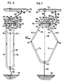
- a block-shaped clamping jaw 157 is exchangeably fastened, which with the (non-circular ) cylindrical end faces 156 of two parallel lateral flanges 155 on the rope curve piece 154 cooperate in such a way that the rope curve piece moves from its open position according to FIG. 7 outside of the support frame 110 to its closed position according to FIG. 6 within the support frame with its end faces 156 the clamping jaws 157 comes closer and closer until it has accrued there and secures the extended position of the knee lever 138 that is reached when the neck frame is closed.
- the clamping jaw 157 must also be exchanged for adaptation to the changed neck width. It is essential that the end faces 156 of the rope curve piece 154 do not run concentrically but rather eccentrically with respect to the knee 144 of the toggle lever 138, such that, when the rope curve piece 154 swings into the supporting frame 110, its end faces 156 come closer to themselves 6 moving jaws 157, the radial distance of the end faces 156 from the knee 144 against the pivoting direction of the rope curve piece 154 increases if the pivoting in is considered.
- the longer arm 138.2 of the toggle lever 138 is extended beyond the knee 144 by approximately the length of the shorter toggle arm 138.1; with its underside, this extension 176 forms the stop for an adjusting screw 174 which is screwed into the support frame 110 from below and is secured and determines the opening position of the cable curve piece 154, as can be seen from FIG. 7.
- the set screw 174 is screwed into the horizontal leg of the lower plate part 110.2.1 of the rear frame half 110.2, so that its head located below is arranged next to one of the opening levers 112 and can also be reached in its opening position in which it must be adjusted.
- the adjusting screw 74 is omitted for the adjusting screw 174, while the adjusting screw 48 serving as a stop for an opening lever 112 is not shown, but is also present in the same place in the variant of the embodiment.
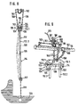
- a cable winch 180 with a ratchet lock 186 is provided in its variant for pushing the operating rod 162 back and forth for the purpose of opening the neck frame or adjusting the readiness for self-catching of the neck frame.
- the shaft 178 of the winch 180 is rotatably mounted on the top tube 164 and provided with a hand crank 173.
- a cable drum 182 of the winch 180 which is seated in a rotationally fixed manner on the shaft 178, is covered with two opposite cables 183 and 184, the ends of which are not fastened to the drum, run away from the drum in opposite directions and are each fastened to the rod 162 by means of hooks and eyes, for example , as can be seen from Fig. 9.
- a ratchet wheel 188 belongs to the ratchet mechanism 186, which forms one of the two flanges of the cable drum 182 and is provided with a circumferential toothing with which a pressure pawl 187 pivotably mounted on the winch 180 interacts in both directions of rotation of the cable drum 182. Therefore, the pawl 187 must be lifted from the locking wheel 188 by hand if the cable drum 182 is to be rotated in one direction or the other by means of the hand crank 173.
Description
Die Erfindung betrifft einen Selbstfanghalsrahmen für grössere Tiere, insbesondere Rinder, mit einem in einem Tierstand aufhängbaren Traggestell; mit zwei in einer im wesentlichen vertikalen Ebene liegenden zweiarmigen Öffnungshebeln, die symmetrisch zu einer vertikalen Ebene angeordnet sind, welche auf der Ebene der Öffnungshebel senkrecht steht, und welche an ihren oberen Enden um zur Symmetrieebene parallele, im wesentlichen waagrechte Achsen drehbar am Traggestell gelagert sind; mit zwei in der Ebene der Öffnungshebel symmetrisch zur Symmetrieebene angeordneten, zweiarmigen Schliesshebeln, die mit ihren oberen Enden mit den unteren Enden der Öffnungshebel gelenkig verbunden und an ihren unteren Enden angelenkt sind, wobei die Anlenkungsstelle(n) mittels eines biegsamen Stranges mit dem Stallboden verbunden ist/sind; mit einem am Traggestell angeordneten Schloss zum reversiblen Verriegeln der Öffnungshebel in deren im wesentlichen vertikaler Schliessstellung und mit einem Seilzug zum Entriegeln des Schlosses, welcher am Knie eines Kniehebels angreift, dessen Arme an den oberen Enden der Öffnungshebel oberhalb der Drehpunkte dieser Öffnungshebel angelenkt und im Schliesszustand gestreckt sind.The invention relates to a self-catching neck frame for larger animals, in particular cattle, with a support frame which can be suspended in an animal stall; with two two-armed opening levers lying in a substantially vertical plane, which are arranged symmetrically to a vertical plane which is perpendicular to the plane of the opening levers, and which at their upper ends are rotatably mounted on the supporting frame about axes which are parallel to the plane of symmetry and are essentially horizontal ; with two two-armed locking levers arranged in the plane of the opening levers symmetrically to the plane of symmetry, the upper ends of which are articulated to the lower ends of the opening levers and articulated at their lower ends, the articulation point (s) being connected to the floor of the barn by means of a flexible strand is / are; with a lock arranged on the support frame for reversibly locking the opening levers in their essentially vertical closed position and with a cable for unlocking the lock, which engages the knee of a knee lever, the arms of which are articulated at the upper ends of the opening levers above the pivot points of these opening levers and in the closed state are stretched.
Die Anmelderin hat sich unter Bezugnahme auf die ältere Anmeldung Nr. 3322217.7 in der Bundesrepublik Deutschland freiwillig eingeschränkt und gesonderte Patentansprüche für die Bundesrepublik Deutschland vorgelegt.The applicant voluntarily restricted himself in the Federal Republic of Germany with reference to the earlier application No. 3322217.7 and submitted separate claims for the Federal Republic of Germany.
Bei einem ausder DE-A-31 36 861 (Fig. 1,2 mit 10, 11) bekannten Selbstfanghalsrahmen dieser Art sind die Kniehebelarme (39) gleich lang und greift das Zugseil (38) exakt am Knie des Kniehebels (39,39) an. Zur Unterstützung der umkehrbaren Spreizbewegung der die Öffnungs- und Schliesshebel (10) beziehungsweise (7) verbindenden Gelenke (9) sind die Öffnungshebel mit einer Feder (Zugefeder 22 oder Druckfeder 22a) versehen, die während des Öffnens und Schliessens des Selbstfanghalsrahmens ein Maximum an Expansion beziehungsweise Kompression erfährt, dessen Überschreitung den Schliess- beziehungsweise Öffnungszustand des Rahmens herbeiführt, der im Falle eines einzelnen Rahmens beispielsweise durch ein Klinkengesperr gesichert wird.In a self-catching neck frame of this type known from DE-A-31 36 861 (FIGS. 1, 2, 10, 11), the toggle arms (39) are of the same length and grips the pull cable (38) exactly on the knee of the toggle lever (39, 39). at. To support the reversible spreading movement of the joints (9) connecting the opening and closing levers (10) and (7), the opening levers are provided with a spring (
An dem bekannten Selbstfanghalsrahmen ist deshalb nachteilig, dass entweder eine sogenannte Gruppenauslösung, das heisst das gleichzeitige Öffnen mehrerer Rahmen, nicht möglich ist, oder dass schon die Einzelauslösung, erst recht aber die Gruppenauslösung, einen verhältnismässig grossen Zugkraftaufwand erfordert, der über den Seilzug aufzubringen ist.A disadvantage of the known self-catching neck frame is that either a so-called group release, i.e. the simultaneous opening of several frames, is not possible, or that the single release, and even more so the group release, requires a relatively large amount of tractive effort, which has to be applied via the cable .
Der Erfindung liegt daher die Aufgabe zugrunde, einen Selbstfanghalsrahmen zu schaffen, der nicht nur einen zuverlässigen Selbstfang des Tieres, sondern auch eine sichere Verriegelung der Offnungshebel in deren Schliessstellung und eine leichtgängige Aufschwenkung derselben nach Entriegelung gewährleistet, so dass eine Gruppenauslösung von Hand bequem möglich ist.The invention is therefore based on the object of providing a self-catching neck frame which not only ensures reliable self-catching of the animal, but also secure locking of the opening levers in their closed position and easy pivoting open of the same after unlocking, so that group triggering by hand is easily possible .
Diese Aufgabe ist bei einem Selbstfanghalsrahmen der eingangs genannten Art erfindungsgemäss dadurch gelöst, dass die Kniehebelarme ungleich lang sind und der kürzere Arm des Kniehebels über dessen angenähert faltbares Knie hinaus verlängert ist; dass an der Verlängerung des kürzeren Kniehebelarmes ein kreisbogenförmiges Steilkurvenstück so befestigt ist, dass der Kreiskurvenmittelpunkt mit dem Kniepunkt zusammenfällt; und dass das Zugseil bei geschlossenem Rahmen über das Kurvenstück gelegt und am unteren Kurvenstückende befestigt ist. Die Sicherung der Schliesslage des gestreckten Kniehebels gegen das Beugen seines Knies nach unten kann mittels eines gestellfesten Anschlages oder durch die Straffung eines nicht dehnbaren Zugseiles erfolgen. Dadurch wird vorteilhafterweise erreicht, dass der erfindungsgemässe Selbstfanghalsrahmen bei hinreichend sicherer Verriegelung seiner Öffnungshebel eine relativ leichtgängige Öffnung desselben bei einer Gruppenauslösung mehrerer gleicher Rahmen gestattet.This object is achieved according to the invention in a self-catching neck frame of the type mentioned at the outset in that the toggle lever arms are of unequal length and the shorter arm of the toggle lever is extended beyond its approximately foldable knee; that an arc-shaped steep curve piece is attached to the extension of the shorter toggle lever arm so that the center of the curve curve coincides with the knee point; and that the traction cable is placed over the curve piece and closed at the lower end of the curve piece when the frame is closed. The closed position of the extended toggle lever can be secured against bending its knee downwards by means of a stop fixed to the frame or by tightening a non-stretchable pull rope. It is thereby advantageously achieved that the self-locking neck frame according to the invention, with a sufficiently secure locking of its opening levers, permits a relatively smooth opening thereof when several identical frames are triggered in a group.
Bei einer bevorzugten Ausführungsform des erfindungsgemässen Selbstfanghalsrahmens sind die Verlängerung des kürzeren Kniehebelarmes und das bei geschlossenem Rahmen untere Ende des Kurvenstückes mittels eines Armes starr verbunden, der sich senkrecht zur Verlängerung erstreckt. Dieser Arm stellt einen Hebelarm beträchtlicher Länge dar, welcher die Betätigung des Kniehebels erleichtert.In a preferred embodiment of the self-catching neck frame according to the invention, the extension of the shorter toggle lever arm and the lower end of the curve piece when the frame is closed are rigidly connected by means of an arm which extends perpendicular to the extension. This arm represents a lever arm of considerable length, which facilitates the operation of the knee lever.
Bei der bevorzugten Ausführungsform weist das Traggestell für den Drehpunkt eines Öffnungshebels eine waagrechte Reihe von im wesentlichen waagrechten Bohrungen zur wahlweisen Aufnahme eines Gelenkzapfens auf, und sind ungefähr symmetrisch zur Symmetrieebene angeordnete Bohrungen durch je einen Gelenkzapfen belegt, deren waagrechter Abstand die Halsweite des geschlossenen Rahmens bestimmt. Damit ist es auf einfache Weise möglich, den erfindungsgemässen Selbstfanghalsrahmen der Tiergrösse, nämlich der Halsbreite, individuell anzupassen, so dass ein Tier, das sich im Halsrahmen selbst gefangen hat, seinen breiteren Kopf nicht zwischen den im Schliesszustand überall denselben senkrechten Abstand voneinander aufweisenden Öffnungs-und Schliesshebeln hindurch zurückziehen und sich dadurch ungewollt befreien kann.In the preferred embodiment, the support frame for the pivot point of an opening lever has a horizontal row of essentially horizontal bores for optionally receiving a hinge pin, and bores arranged approximately symmetrically to the plane of symmetry are each occupied by a hinge pin, the horizontal distance of which determines the neck width of the closed frame . It is thus possible in a simple manner to individually adapt the self-catching neck frame according to the invention to the animal size, namely the neck width, so that an animal that has caught itself in the neck frame does not have its wider head between the opening distances that are the same everywhere from one another in the closed state. and pull the locking levers back and thereby accidentally free themselves.
Bei der bevorzugten Ausführungsform ist das Traggestell mit verstellbaren Schraubanschlägen für die oberen Arme der Öffnungshebel und für den Verbindungsarm versehen, damit im Schliesszustand des erfindungsgemässen Selbstfanghalsrahmens dessen Kniehebelknie und Kniehebelanlenkungspunkte eine Zugentlastung erfahren, beziehungsweise dass im Öffnungszustand dieselben Gelenke nicht überlastet werden, wenn das Tier vor der Rahmenschliessung seinen durch die Rahmenöffnung gesteckten Hals gegen einen der Offnungshebel wirft.In the preferred embodiment, the support frame is provided with adjustable screw stops for the upper arms of the opening lever and for the connecting arm, so that when the self-catching neck frame according to the invention is closed, its knee lever knee and knee lever pivot points are relieved of strain, or that the same joints are not overloaded in the opening state if the animal is in front the frame lock throws its neck through the frame opening against one of the opening levers.
Bei der bevorzugten Ausführungsform weist das Traggestell zwei bezüglich der Ebene der Öffnungshebel symmetrisch ausgebildete, gekröpfte Platten auf, deren untere, einander näherliegende Teile die Öffnungshebel an ihren Drehpunkten einschliessen, und deren obere, einander fernerstehende Teile den Kniehebel und das Seilkurvenstück zwischen sich einschliessen. Dadurch wird insbesondere bei rechtwinkliger Kröpfung eine kompakte, glatte äussere Gestalt des Gestells bei einfacher Lagerung der Öffnungshebel an deren Drehpunkten erreicht.In the preferred embodiment, the support frame has two cranked plates which are symmetrical with respect to the plane of the opening levers, the lower plates of which are closer to one another Parts include the opening levers at their pivot points, and their upper, spaced-apart parts include the toggle lever and the rope curve piece between them. As a result, a compact, smooth outer shape of the frame is achieved with simple storage of the opening levers at their pivot points, in particular with right-angled cranking.
Bei der bevorzugten Ausführungsform, deren beide Schliesshebel an ihren unteren Enden an den oberen Enden eines U-förmigen Bügels angebracht sind, dessen Joch mittels des biegsamen Stranges mit dem Stallboden verbunden ist, sind die mit den Schliesshebeln gelenkig verbundenen oberen Enden des Bügels durch je ein im wesentlichen vertikales Verbindungsstück gebildet, das auf der Aussenseite jedes Bügelschenkels befestigt und in seiner Länge so bemessen ist, dass die unteren Enden der Schliesshebel in deren im wesentlichen vertikaler Schliessstellung annähernd fugenlos an die oberen Enden der Bügelschenkel anschliessen. Daran ist vorteilhaft, dass sich das Tier, wenn es seinen Hals zwischen den Schliesshebeln diesen entlang nach unten bewegt, nicht mit seinem Hals an den oberen Enden des U-förmigen Bügels verletzen kann, weil die vom Tier selbst vertikal gestellten Schliesshebel danach glatt in die Bügelschenkel übergehen, so dass der Tierhals ohne Gefahr im Bügel weiter abgesenkt werden kann.In the preferred embodiment, the two locking levers of which are attached at their lower ends to the upper ends of a U-shaped bracket, the yoke of which is connected to the floor of the barn by means of the flexible strand, the upper ends of the bracket which are articulated to the locking levers are each one formed essentially vertical connector, which is attached to the outside of each bracket leg and is dimensioned in length so that the lower ends of the locking lever in their substantially vertical closed position connect almost seamlessly to the upper ends of the bracket legs. This is advantageous in that the animal, when it moves its neck downward between the locking levers, cannot injure its neck at the upper ends of the U-shaped bracket, because the locking levers which the animal itself has set vertically thereafter smoothly into the Pass over the temple legs so that the animal neck can be lowered further without any danger in the temple.
Bei einer anderen Ausführungsform sind die beiden Schliesshebel an ihren unteren Enden mittels eines Drehzapfens, dessen Achse auf der Ebene der Öffnungshebel senkrecht steht, gelenkig miteinander verbunden und ist ausserdem der Drehzapfen mittels des biegsamen Stranges bei geöffnetem Rahmen straff mit dem Stallboden verbunden. Dadurch ist es wegen des Wegfalls des U-Bügels möglich, die Weite des geöffneten Rahmens zu vergrössern und das mit seinem Hals darin steckende Tier den Rahmen wahlweise durch Absenken seines Halses auf die gefesselte gemeinsame Anlenkungsstelle der beiden Schliesshebel oder vorzugsweise durch vorwärts gerichtetes Auslenken der mittleren Hebelgelenke mittels des Tierhalses schliessen zu lassen, wie das in der DE-A-27 22 730 angeregt wurde.In another embodiment, the two locking levers are articulated at their lower ends by means of a pivot, the axis of which is perpendicular to the level of the opening lever, and the pivot is also tightly connected to the floor of the barn by means of the flexible strand when the frame is open. As a result of the omission of the U-bracket, it is possible to increase the width of the open frame and the animal stuck in it with its neck either by lowering its neck to the tied joint articulation point of the two locking levers or preferably by forwardly deflecting the middle one To let lever joints close by means of the animal's neck, as was suggested in DE-A-27 22 730.
Bei dieser zweiten Ausführungsform ist der längere Arm des Kniehebels über dessen Knie hinaus verlängert und schlägt die Verlängerung an einer Stellschraube an, die wiederum in das Traggestell eingreift. Dadurch ist der aussenliegende Kopf der Stellschraube auch dann zugänglich, wenn das Seilkurvenstück seitlich aus dem Traggestell herausgeklappt ist.In this second embodiment, the longer arm of the toggle lever is extended beyond its knee and strikes the extension on an adjusting screw, which in turn engages in the support frame. As a result, the outside head of the adjusting screw is also accessible when the rope curve piece is folded out laterally from the supporting frame.
Bei der zweiten Ausführungsform ist das kreisbogenförmige Seilkurvenstück mit zwei das Zugseil zwischen sich aufnehmenden seitlichen Flanschen versehen, deren Stirnflächen bezüglich des Kniepunktes exzentrisch verlaufen und mit einem am oberen Arm des am längeren Kniehebelarm angelenkten Öffnungshebels befestigten Klemmbacken zur Arretierung der Öffnungshebel in deren Schliessstellung zusammenwirkt. Dadurch wird verhindert, dass die Lagerstellen der Öffnungshebel am Traggestell allmählich ausschlagen, wenn das gefangene Tier seinen Hals seitlich hin und her wirft, der im allgemeinen nicht beidseitig an den Öffnungshebeln anliegt.In the second embodiment, the arc-shaped rope curve piece is provided with two side flanges which receive the pull rope between them, the end faces of which extend eccentrically with respect to the knee point and cooperates with a clamping jaw attached to the upper arm of the opening lever articulated on the longer knee lever arm for locking the opening lever in its closed position. This prevents the bearing points of the opening levers on the support frame from gradually knocking out when the captive animal tosses its neck back and forth, which generally does not rest on both sides of the opening levers.
Der Klemmbacken der zweiten Ausführungsform, bei der ebenfalls mehrere Lagerstellen für einen Öffnungshebel am Traggestell vorgesehen sind, ist auswechselbar befestigt, so dass er in ver-. schiedenen, den einzelnen Lagerstellen zugeordneten passenden Grössen verwendet werden kann.The clamping jaws of the second embodiment, in which a plurality of bearing points for an opening lever are likewise provided on the supporting frame, are fastened so that they can be exchanged. different suitable sizes assigned to the individual bearing points can be used.
Der erfindungsgemässe Selbstfanghalsrahmen ist zur bekannten Aufhängung an einem Stallgerüst aus mehreren vertikalen Standrohren und aus einem deren obere Enden verbindenden waagrechten Oberrohr bestimmt und geeignet. Zweckmässig ist das Zugseil des Rahmens deshalb an seinem kurvenstückfernen Ende an einer waagrechten Bedienungsstange für mehrere Rahmen festgelegt, welche in ihrer geraden Längsrichtung hin und her verschiebbar längs des Oberrohres an diesem gelagert und mittels eines Handhebels bewegbar ist. Dadurch kann eine einfache Gruppenauslösung mehrerer Rahmen erfolgen.The self-catching neck frame according to the invention is intended and suitable for the known suspension on a stable frame consisting of a plurality of vertical standpipes and a horizontal top pipe connecting their upper ends. The traction cable of the frame is therefore expediently fixed at its end remote from the curve on a horizontal operating rod for a plurality of frames, which can be moved back and forth in its straight longitudinal direction along the top tube and can be moved by means of a hand lever. This enables a simple group triggering of several frames.
Dazu ist speziell vorgesehen, dass an der beweglichen Bedienungsstange und am festliegenden Oberrohr eine Lasche bzw. ein zweiarmiger Schwenkhebel als Handhebel endseitig angelenkt sind, wobei die Lasche ausserdem am Schwenkhebel zwischen dessen beiden Enden angelenkt ist; und dass der Handhebel über den Punkt der Anlenkung der Lasche am Hebel als Totpunkt hinaus beim Schwenken des Hebels im Sinne einer Rahmenöffnung bewegbar ist, wobei der Schwenkhebel auf einen Anschlag am Oberrohr trifft. Eine durch Anschläge begrenzte Schwenkbewegung ist besonders bequem und schnell ausführbar, so dass die Gruppenauflösung wenig Kraft bzw. Zeit erfordert.For this purpose, it is specifically provided that a tab or a two-armed pivot lever is articulated at the end as a hand lever on the movable operating rod and on the fixed top tube, the tab also being articulated on the pivot lever between its two ends; and that the hand lever can be moved beyond the point of articulation of the tab on the lever as a dead center when the lever is pivoted in the sense of a frame opening, the pivot lever meeting a stop on the top tube. A swivel movement limited by stops can be carried out particularly conveniently and quickly, so that the group resolution requires little force or time.
Ist das Traggestell des Rahmens wie bekannt mittels zweier kurzer Kettenstücke am Oberrohr des Stallgerüstes aufhängbar, so kann an der Aufhängungsstelle am Oberrohr eine Führung für die Bedienungsstange vorgesehen sein, z. B. eine Öse, die auf oder unter einer Platte sitzt, die am Oberrohr durch zwei Schraubverbindungen mittels einer Bügelschraube mit Muttern befestigt ist.If, as is known, the supporting frame of the frame can be suspended from the top tube of the stable structure by means of two short chain pieces, a guide for the operating rod can be provided at the suspension point on the top tube, for. B. an eyelet that sits on or under a plate that is attached to the top tube by two screw connections by means of a bow screw with nuts.
Falls zur Festlegung des Zugseils an der Bedienungsstange eine Öse bzw. ein Haken vorgesehen sind, können durch Trennen von Öse und Haken einzelne ausgewählte Rahmen einfach von der Gruppenauslösung aller Rahmen ausgenommen werden.If an eyelet or a hook is provided to fix the pull rope on the operating rod, individual selected frames can easily be excluded from the group triggering of all frames by separating the eyelet and hook.
Bei der zweiten Ausführungsform ist der Haken oder die Öse zur Festlegung des Zugseiles längs der Bedienungsstange verschiebbar an dieser gelagert, so dass die Befestigungsstelle beliebig gewählt werden kann.In the second embodiment, the hook or the eyelet for fixing the traction cable is slidably mounted on the operating rod so that the attachment point can be chosen as desired.
Bei der zweiten Ausführungsform ist als Hebel zum Bewegen der Bedienungsstange eine Handkurbel vorgesehen, welche die Welle einer am Oberrohr festgelegten Seilwinde dreht, deren Seiltrommel von zwei gegenläufig aufgewickelten Seilen umschlungen ist, deren straffe freie Enden in einander entgegengesetzte Richtungen parallel zur Bedienungsstange weisend an dieser festgelegt sind. Mittels dieser handbetätigten Seilwinde kann eine Einzel- oder insbesondere Gruppenauslösung des in Ein- bzw. Mehrzahl vorhandenen erfindungsgemässen Rahmens durch geringeren menschlichen Kraftaufwand erfolgen als bei der ersten Ausführungsform mit manuell umlegbarem Schwenkhebel.In the second embodiment, a hand crank is provided as a lever for moving the operating rod, which turns the shaft of a cable winch fixed to the top tube, the cable drum of which is wrapped by two cables wound in opposite directions, the tight free ends of which are parallel in opposite directions facing the operating rod are fixed to it. By means of this manually operated cable winch, the frame according to the invention, which is present in one or a plurality, can be released individually or in particular in a group with less effort than in the first embodiment with a manually pivotable pivoting lever.
Die Seilwinde und/oder die freien Enden ihrer beiden Seile sind bei der zweiten Ausführungsform längs der Bedienungsstange verschiebbar an dieser festgelegt, so dass auch diese drei Befestigungsstellen der Seilwinde beliebig gewählt werden können. Die Seilwinde weist bei der zweiten Ausführungsform ein Klinkengesperre auf, dessen greifbare DruckkIinke mit einem auf der Trommelwelle der Winde sitzenden, aussenverzahnten Sperr-Rad, das ein Flansch der Trommel sein kann, eine Lockerung des gespannten Zugseiles sperrend, zusammenwirkt. Dieses Gesperre verhindert bei Unterbrechung der Rahmenöffnung eine selbsttätige Rahmenschliessung unter dem Einfluss des Gewichts der Hebelpaare und des angehängten Fessel-Stranges sowie des angehobenen, aber noch nicht bis zum Anschlag beiseite geschwenkten Seilkurvenstückes. Zum Lockern des Zugseiles kann die Sperrklinke von Hand ausser Eingriff in das Sperr-Rad gebracht werden.In the second embodiment, the cable winch and / or the free ends of its two cables are slidably attached to the operating rod, so that these three fastening points of the cable winch can also be chosen as desired. In the second embodiment, the cable winch has a ratchet ratchet, the graspable pressure pawl of which interacts with an externally toothed ratchet wheel which is seated on the drum shaft of the winch and which can be a flange of the drum, blocking a loosening of the tensioned pull rope. When the frame opening is interrupted, this locking mechanism prevents the frame from closing automatically under the influence of the weight of the pairs of levers and the attached ankle chain as well as the rope curve piece that has been raised but not yet pivoted as far as it will go. To loosen the traction cable, the pawl can be brought out of engagement in the locking wheel by hand.
Zur Verriegelung der Seiltrommel im Schliess-und Öffnungszustand des Rahmens ausgebildet ist das Klinkengesperre der zweiten Ausführungsform, damit der geschlossene Rahmen nicht ohne bewusste Entsperrung versehentlich durch Drehen der verwechselten Handkurbel geöffnet wird.To lock the rope drum in the closed and open state of the frame, the ratchet mechanism of the second embodiment is designed so that the closed frame is not accidentally opened by turning the mixed-up crank handle without deliberate unlocking.
Imfolgenden ist die Erfindung anhand der durch die Zeichnung beispielhaft dargerstellten bevorzugten Ausführungsform des erfindungsgemässen Selbstfanghalsrahmens und einer Variante im einzelnen erläutert. Es zeigt:
- Fig. eine frontale Ansicht der Ausführungsform im Öffnungszustand (rechts) und im Schliesszustand (links);
- Fig. 2 eine Seitenansicht des SchlossesderAusführungsform im Schliesszustand;
- Fig. 3 die gleiche Ansicht im Öffnungszustand;
- Fig. 4 einen Querschnitt nach der Linie IV-IV in Fig. 2 durch das Schloss der Ausführungsform im Schliesszustand;
- Fig. 5 eine Draufsicht auf das Schloss der Ausführungsform im Schliesszustand;
- Fig. 6 und 7 der linken bzw. rechten Hälfte von Fig. 1 entsprechende Ansichten der Variante der Ausführungsform;
- Fig. 8 eine Seitenansicht dieser Variante im Öffnungszustand in Richtung des Pfeiles VIII in Fig. 7; und
- Fig. 9 eine perspektivische Ansicht des Schlosses der Variante in Verbindung mit einer Seilwinde derselben.
- Fig. A frontal view of the embodiment in the open state (right) and in the closed state (left);
- Fig. 2 is a side view of the lock of the embodiment in the closed state;
- 3 shows the same view in the open state;
- 4 shows a cross section along the line IV-IV in Figure 2 by the lock of the embodiment in the closed state.
- 5 shows a plan view of the lock of the embodiment in the closed state;
- 6 and 7 of the left and right half of FIG. 1 corresponding views of the variant of the embodiment;
- 8 shows a side view of this variant in the open state in the direction of arrow VIII in FIG. 7; and
- Fig. 9 is a perspective view of the lock of the variant in connection with a cable winch of the same.
Im Ausführungsbeispiel besteht der erfindungsgemässe Selbstfanghalsrahmen hauptsächlich aus einem aufgehängten Traggestell 10, aus zwei gleichen, geraden, rohrförmigen Öffnungshebeln 12, aus zwei den Öffnungshebeln gleichenden, kürzeren Schliesshebeln 14, aus einem in U-Form gebogenen Rohrbügel 16, der mittels einer Unterkette 18 lose am Stallboden 20 verankert ist, aus zwei parallelen stabförmigen Verbindungsstücken 22 zwischen dem Bügel 16 und den zwei Schliesshebeln 14 und aus einem im Traggestell 10 angeordneten Schloss 24 zum reversiblen Verriegeln der zwei Öffnungshebel 12 in deren im wesentlichen vertikaler Schliessstellung.In the exemplary embodiment, the self-catching neck frame according to the invention mainly consists of a suspended
Die beiden Offnungshebel 12 bestehen je aus einem kürzeren oberen Arm 12.1 sowie aus einem längeren unteren Arm 12.2, von denen die oberen Arme ganz im Traggestell 10 angeordnet sind und die unteren Arme grösstenteils aus diesem Gestell unten herausragen. Die unteren Enden der Öffnungshebel 12 und die oberen Enden der Schliesshebel 14 sind derart gelenkig miteinander verbunden, dass im Schliesszustand des Selbstfanghalsrahmens, wobei auf jeder Schmalseite des Rahmens der Öffnungshebel 12 und der angelenkte Schliesshebel 14 geradlinig übereinander angeordnet sind, die Gelenkstelle 26 nach vorn bewegt werden kann, so dass der Öffnungshebel und der angelenkte Schliesshebel einen stumpfen Innenwinkel bilden, und dass beim Übergang vom Schliesszustand zum Öffnungszustand des Rahmens die zwei Hebelpaare 12-14 zwei koplanare, an den Gelenkstellen 26 ungefähr rechtwinklige Dreiecke bilden, die zusammen ungefähr ein Viereck mit maximaler Entfernung der beiden in gleicher Höhe liegenden Gelenkstellen 26 voneinander formen. Ungefähr am Übergang der zwei oberen Drittel jedes Schliesshebels 14 zu dessen unterem Drittel ist dieser Hebel seitlich am oberen Ende eines der zwei Verbindungsstücke 22 angelenkt, das seinerseits auf der Aussenseite eines der zwei geraden parallelen Bügelschenkel 16.1 beziehungsweise 16.2 diesen derart überlappend befestigt ist, dass im Schliesszustand des Rahmens das untere Drittel jedes Schliesshebels 14 an der Innenseite des ihm zugeordneten Bügelschenkels anliegt und dabei dem Bügelschenkel ohne wesentlichen Abstand davon geradlinig gegenübersteht. Das halbkreisförmige Bügeljoch 16.3 lagert an seinem tiefsten Punkt die Unterkette 18, deren Länge so bemessen ist, dass sie im Öffnungszustand des Rahmens gestrafft ist. Die gestraffte Unterkette 18 markiert die Lage einer vertikalen Symmetrieebene 28, bezüglich der die Öffnungshebel 12 und die Schliesshebel 14 sowohl im Schliesswie im Öffnungszustand des Rahmens sowie die Schenkel des Bügels 16 und die Verbindungsstükke 22, welche Rahmenteile alle gerade sind, symmetrisch angeordnet sind.The two opening
Das Traggestell 10 weist zwei fest miteinander verbundene Hälften 10.1 beziehungsweise 10.2 auf, die bezüglich einer bei richtiger und freier Aufhängung des Gestelles vertikal angeordneten Rahmenebene 30 symmetrisch angeordnet und ausgebildet sind, in welcher die Hebel 12 und 14 sowie der Bügel 16 und die Verbindungsstücke 22 liegen, falls der Rahmen nicht an den Gelenkstellen 26 nach vorn ausgeknickt ist. Jede Gestellhälfte besteht aus einer rechtwinklig abgekröpften Platte, so dass die unteren Plattenteile 10.1.1 beziehungsweise 10.2.1 einander beträchtlich näher stehen als die oberen Plattenteile 10.1.2 beziehungsweise 10.2.2. Jedes untere Plattenteil 10.1.1 oder 10.2.1 weist auf einer Seite der Symmetrieebene 28 eine Bohrung 32 und auf der anderen Seite dieser Ebene eine waagrechte Reihe von dicht beieinanderliegenden Bohrungen 34 auf, durch die paarweise und je nach dem gewünschten senkrechten Abstand der beiden Offnungshebel 12 voneinander ein sich parallel zur Symmetrieebene 28 waagrecht erstreckender, axial gesicherter Gelenkbolzen 36 gesteckt ist, an dem je einer der Öffnungshebel12 hängt und dadurch schwenkbar gelagert ist. An den in den Raum zwischen den Traggestellhälften 10.1 beziehungsweise 10.2 hineinragenden oberen Hebelarmen 12.1 ist je ein diese zwei Arme verbindender Kniehebel 38 mit den freien Enden seiner zwei Arme 38.1 und 38.2 angelenkt, wobei der den zugeordneten oberen Hebelarm 12.1 aufnehmende längere Hebelarm 38.2 an seinem freien Ende ebenfalls eine gerade Reihe von Bohrungen 40 aufweist, die den Bohrungen 34 entsprechen und mit diesen paarweise zur Bestimmung der Rahmenweite verwendet werden, indem ein Gelenkbolzen 42 den oberen Arm 12.1 des Öffnungshebels mit der passenden Stelle des längeren Kniehebelarmes 38.2 verbindet. Eine entsprechende Verbindung ist zwischen dem kürzeren Kniehebelarm 38.1 und dem oberen Arm 12.1 des anderen Öffnungshebels vorgesehen; diese Verbindung ist aber nicht verstellbar. Das mit einem Gelenkbolzen 46 versehene Knie 44 des Kniehebels 38 ist bei vertikal gestellten Öffnungshebeln 12, die in dieser Stellung mit ihren oberen Armen 12.1 an je einer seitlich am Traggestell 10 angebrachten Stellschraube 48 anschlagen, gestreckt.The
An einer kurzen Verlängerung 50 des kürzeren Kniehebelarmes 38.1 über den Kniegelenkbolzen 46 hinaus ist im rechten Winkel zu diesem Arm ein Verbindungsarm 52 angesetzt, an dessen freies Ende ein kreisbogenförmiges Seilkurvenstück 54 angeformt ist, dessen Zylinderachse mit der Achse des Kniegelenkbolzens 46 zusammenfällt. Dabei ist die Anordnung so getroffen, dass der Verbindungsarm 52 bei geschlossenem Rahmen ungefähr vertikal nach unten zeigt und das freie Ende des Seilkurvenstückes 54 ungefähr vertikal nach oben zeigt, wenn das Knie 44 gerade gestreckt ist. Auf der Aussenseite des freien Endes des Verbindungsarmes 52 ist ein Ende eines nicht dehnbaren Zugseiles 58 befestigt, das um die abgerundete Anformungsstelle zwischen Verbindungsarm 52 und Kurvenstück 54 aussen herumgelegt ist und die konvexe Seite des Kurvenstückes umschlingt, und zwar vollständig bei geschlossenem Rahmen. Damit das Knie 44 beim Schliessen des Rahmens nicht nach unten durchgedrückt werden kann, wobei sich der Rahmen wieder öffnen würde, steht das Zugseil 58 unter einer entsprechend grossen Zugspannung; es ist dazu an seinem kniefernen Ende an einem Haken 60 eingehängt, der an einer waagrechten Bedienungsstange 62 für mehrere Selbstfanghalsrahmen befestigt ist. Die Stange 62 ist in ihrer geraden Längsrichtung hin und her verschiebbar längs eines waagrechten Oberrohres 64 gelagert, das sich längs mehrerer Tierstände, die mit je einem Rahmen versehen sind, erstreckt und an den oberen Enden mehrerer vertikaler Standrohre 66 fest gelagert ist. Am Oberrohr 64 ist mittels zweier kurzer Kettenstücke 68 das Traggestell 10 jedes Rahmens so aufgehängt, dass die beiden Kettenstücke in der Symmetrieebene 28 des Rahmens auf verschiedenen Seiten der Rahmenebene 30 angeordnet sind. An einer geeigneten Stelle des aus den Rohren 64 und 66 bestehenden Stallgerüstes sind an der beweglichen Bedienungsstange 62 und am festliegenden Oberrohr 64 eine Lasche 70 beziehungsweise ein zweiarmiger Schwenkhebel 72 endseitig angelenkt. Die Lasche 70 ist ausserdem am Schwenkhebel 72 zwischen dessen beiden Enden angelenkt, so dass eine Schwenkung des Hebels 72 über nahezu 180° zwischen zwei Lagen, in denen sich der Hebel ungefähr parallel zum Oberrohr 64 erstreckt, zu einer bestimmten Verschiebung der Bedienungsstange 62 führt, die dabei am Seil 58 zieht oder dieses lockert. Beim Straffen des Zugseiles 58 löst sich dieses zunehmend vom Umfang des Seilkurvenstückes 54, das den kürzeren Kniehebelarm 38.1 mittels des Verbindungsarmes 52 um den Gelenkbolzen 42 schwenkt, der den kürzeren Kniehebelarm 38.1 und einen der oberen Arme 12.1 der Öffnungshebel verbindet, wobei das Knie 44 nach oben gebeugt und darüber hinaus überbeugt wird, bis es nahezu gefaltet ist. In diesem Kniezustand, der dadurch erreicht wird, dass der Gelenkpunkt der Verbindung von kürzerem Kniehebelarm 38.1 und angelenktem Hebelarm 12.1 durch die Verbindungsgerade von Kniepunkt und Gelenkpunkt der Verbindung von Öffnungshebel 12 und Traggestell 10 wandert, muss, im Ausführungsbeispiel als Anschlag für die dem Seilkurvenstück 54 zugewandte Seite des Verbindungsarmes 52, eine Stellschraube 74 am Traggestell 10 angeordnet sein, damit ein Überfalten den Knies 44 vermieden wird und es deshalb möglich ist, durch seitliches Hinausschwenken des am kürzeren Kniehebelarm 38.1 angelenkten oberen Hebelarmes 12.1 mittels des Verbindungsarmes 52 das Seilkurvenstück 54 vom Tier, das den vorher geöffneten Rahmen selbst schliesst, zurückdrehen zu lassen, wobei das lose Zugseil 58 sich allmählich an den Umfang des Kurvenstückes anlegt und schliesslich gespannt wird. Voraussetzung hierfür ist, dass der Schwenkhebel 72 nach der Gruppenauslösung aller an die Bedienungsstange 62 angeseilten, einander gleichenden Selbstfanghalsrahmen sofort zurückgeschwenkt wird, damit ein Selbstfang des Tieres im Rahmen möglich ist.On a
In den die Variante der Ausführungsform gemäss Fig. 1 bis 5 wiedergebenden Fig. 6 bis 9 sind den Teilen der Ausführungsform gleichende oder entsprechende Teile mit um 100 höheren Bezugszahlen versehen. Insoweit gilt die vorstehende Beschreibung der Ausführungsform wörtlich bzw. sinngemäss auch für deren Variante, die im folgenden nur hinsichtlich ihrer Unterschiede zur Ausführungsform beschrieben wird.In FIGS. 6 to 9, which represent the variant of the embodiment according to FIGS. 1 to 5, parts that are the same or corresponding to the parts of the embodiment are provided with reference numbers that are 100 higher. In this respect, the above description of the embodiment also applies literally or analogously to its variant, which is described below only with regard to its differences from the embodiment.
Hier sind die zwei Schliesshebel 14 und der U-förmige Rohrbügel 16 unter Wegfall der Verbindungsstücke 22 und Halbierung des Bügels zu zwei ein langgestrecktes U bildenden L-förmigen Schliesshebeln 114 umgeformt, die an ihren unteren, mit der Unterkette 118 versehenen Enden mittels eines Drehzapfens 117 gelenkig miteinander verbunden sind, wobei der Drehzapfen 117 senkrecht zu der von den beiden Schliesshebeln 114 bestimmten Ebene steht und die Länge der Unterkette 118 so bemessen ist, dass sie straff gespannt ist, wenn der vertikal hängende Halsrahmen geöffnet ist, wie aus den Fig. 7 und 8 ersichtlich ist. I nfolgedessen kann eine Auslenkung der zwei Gelenkstellen 126 zwischen den Öffnungs- und Schliesshebeln 112 bzw. 114 nach vorn oder hinten, beispielsweise in die in Fig. 8 gestrichelt eingezeichnete Hebellage, zu einem Zusammenklappen der beiden Schliesshebel 114 in deren im wesentlichen vertikale Schliessstellung führen, weil die Unterkette 118 den Drehzapfen 117 dabei festhält. Das sich selbst fangende Tier kann also mit seinem Hals entweder nach unten oder nach vorn gehen, um den Halsrahmen zu schliessen.Here are the two locking levers 14 and the
An dem am längeren Arm 138.2 des Kniehebels 138 angelenkten oberen Ende des oberen Armes 112.1 des in den Fig. 6 und 7 linken Öffnungshebels 112 ist auf der dem gegenüberliegenden Hebelarm 112.1 zugewandten Seite ein klotzförmiger Klemmbacken 157 auswechselbar befestigt, der mit den (nicht kreis-)zylindrischen Stirnflächen 156 zweier paralleler seitlicher Flansche 155 am Seilkurvenstück 154 in der Weise zusammenwirkt, dass das Seilkurvenstück bei seiner Bewegung aus seiner Öffnungslage gemäss Fig. 7 ausserhalb des Traggestells 110 in seine Schliesslage gemäss Fig. 6 innerhalb des Traggestells mit seinen Stirnflächen 156 dem Klemmbacken 157 zunehmend näher kommt, bis es dort aufgelaufen ist und die bei geschlossenem Halsrahmen erreichte Strecklage des Kniehebels 138 sichert. Falls der in Fig. 6 linke Öffnungshebel 112 mittels eines anderen Paares von Bohrungen 134 bzw. 140 angelenkt werden soll, muss auch der Klemmbacken 157 zwecks Anpassung an die geänderte Halsweite ausgewechselt werden. Wesentlich ist, dass die Stirnflächen 156 des Seilkurvenstückes 154 in bezug auf das Knie 144 des Kniehebels 138 nicht konzentrisch, sondern exzentrisch verlaufen, dergestalt, dass, da beim Hineinschwenken des Seilkurvenstückes 154 in das Traggestett 110 eine Annäherung seiner Stirnflächen 156 an den sich in seine Sperrstellung gemäss Fig. 6 bewegenden Klemmbacken 157 stattfinden soll, der radiale Abstand der Stirnflächen 156 vom Knie 144 gegen die Schwenkrichtung des Seilkurvenstückes 154 zunimmt, falls das Hineinschwenken betrachtet wird.On the longer arm 138.2 of the
Der längere Arm 138.2 des Kniehebels 138 ist über das Knie 144 hinaus ungefähr um die Länge des kürzeren Kniehebelarmes 138.1 verlängert; diese Verlängerung 176 bildet mit ihrer Unterseite den Anschlag für eine Stellschraube 174, die von unten her in das Traggestell 110 unter Sicherung eingeschraubt ist und die Öffnungslage des Seilkurvenstückes 154 bestimmt, wie aus Fig. 7 ersichtlich ist. Die Stellschraube 174 ist in den waagrechten Schenkel des unteren Plattenteiles 110.2.1 der hinteren Gestellhälfte 110.2 eingeschraubt, so dass ihr unten liegender Kopf neben einem der Öffnungshebel 112 angeordnet und auch in dessen Öffnungsstellung erreichbar ist, in welcher sie justiert werden muss. Für die Stellschraube 174 entfällt die Stellschraube 74, während die als Anschlag für einen Öffnungshebel112 dienende Stellschraube 48 zwar nicht gezeichnet, jedoch an gleicher Stelle auch bei der Variante der Ausführungsform vorhanden ist.The longer arm 138.2 of the
Statt des Schwenkhebels 72 und der ihm zugeordneten Teile der Ausführungsform ist bei deren Variante zur Hin- und Herverschiebung der Bedienungsstange 162 zwecks Halsrahmenöffnung bzw. Einstellung der Selbstfangbereitschaft des Halsrahmens eine Seilwinde 180 mit Klinkengesperre 186 vorgesehen. Die Welle 178 der Winde 180 ist an dem Oberrohr 164 drehbar gelagert und mit einer Handkurbel 173 versehen. Eine drehfest auf der Welle 178 sitzende Seiltrommel 182 der Winde 180 ist mit zwei gegenläufigen Seilen 183 und 184 belegt, deren nicht an der Trommel befestigte Enden in einander entgegengesetzten Richtungen von der Trommel weglaufen und beispielsweise je mittels Haken und Öse an der Stange 162 befestigt sind, wie das aus Fig. 9 ersichtlich ist. Zum Klinkengesperre 186 gehört ein Sperr-Rad 188, das einen der beiden Flansche der Seiltrommel 182 bildet und mit einer Umfangsverzahnung versehen ist, mit der eine schwenkbar an der Winde 180 gelagerte Druckklinke 187 in beiden Drehrichtungen der Seiltrommel 182 zusammenwirkt. Deshalb muss die Druckklinke 187 von Hand vom Sperr-Rad 188 abgehoben werden, wenn die Seiltrommel 182 mittels der Handkurbel 173 in der einen oder anderen Richtung gedreht werden soll.Instead of the
Claims (15)
Applications Claiming Priority (2)
| Application Number | Priority Date | Filing Date | Title |
|---|---|---|---|
| DE3322217A DE3322217C2 (en) | 1983-06-21 | 1983-06-21 | Self-locking neck frame for animals |
| DE3322217 | 1983-06-21 |
Publications (2)
| Publication Number | Publication Date |
|---|---|
| EP0131777A1 EP0131777A1 (en) | 1985-01-23 |
| EP0131777B1 true EP0131777B1 (en) | 1986-08-27 |
Family
ID=6201933
Family Applications (1)
| Application Number | Title | Priority Date | Filing Date |
|---|---|---|---|
| EP84106999A Expired EP0131777B1 (en) | 1983-06-21 | 1984-06-19 | Yoke with automatic closure for animals |
Country Status (2)
| Country | Link |
|---|---|
| EP (1) | EP0131777B1 (en) |
| DE (2) | DE3322217C2 (en) |
Family Cites Families (5)
| Publication number | Priority date | Publication date | Assignee | Title |
|---|---|---|---|---|
| DE7019385U (en) * | 1970-05-25 | 1971-02-11 | Wenners Josef | BARN TIE-UP DEVICE FOR CATTLE. |
| DE7820793U1 (en) * | 1978-07-11 | 1978-10-12 | Suevia Haiges Kg, 7125 Kirchheim | SELF-CATCHING NECK FRAME |
| DE7728870U1 (en) * | 1977-09-17 | 1977-12-22 | Suevia Haiges Kg, 7125 Kirchheim | SELF-CATCHING NECK FRAME FOR Cattle |
| DE2845521A1 (en) * | 1978-10-19 | 1980-04-24 | Hoermann Geb Schimpfle Kreszen | Self adjusting halter for cowshed - has telescopic arms connected to cable winding system controlling size of opening between arms |
| DE3136861A1 (en) * | 1980-09-18 | 1982-08-05 | Vandervelde, Noel, 6838 Pavillons, Florennes | Self-locking neck-bar for large animals |
-
1983
- 1983-06-21 DE DE3322217A patent/DE3322217C2/en not_active Expired
-
1984
- 1984-06-19 DE DE8484106999T patent/DE3460561D1/en not_active Expired
- 1984-06-19 EP EP84106999A patent/EP0131777B1/en not_active Expired
Also Published As
| Publication number | Publication date |
|---|---|
| EP0131777A1 (en) | 1985-01-23 |
| DE3460561D1 (en) | 1986-10-02 |
| DE3322217C2 (en) | 1986-05-15 |
| DE3322217A1 (en) | 1985-01-10 |
Similar Documents
| Publication | Publication Date | Title |
|---|---|---|
| DE1253421B (en) | Device for carrying a floor care device or the like. | |
| CH619111A5 (en) | Lateral delimitation apparatus for a stand for livestock | |
| DE3100405C2 (en) | ||
| EP0131777B1 (en) | Yoke with automatic closure for animals | |
| DE1252162B (en) | Belt wrap for winding metal tape | |
| DE2845521A1 (en) | Self adjusting halter for cowshed - has telescopic arms connected to cable winding system controlling size of opening between arms | |
| DE2722730A1 (en) | Self locking tie-up for cattle - has struts which swivel about points adjacent transverse suspension beam mounted by chain | |
| DE1800076C (en) | Neck frame for cattle | |
| DE2205887C2 (en) | Cattle tie-up device in stalls - has neck frame with side struts and closable connecting elements | |
| DE2554231C3 (en) | Self-locking neck frame attachment device for cattle | |
| AT53691B (en) | Telescopic mast. | |
| DE2702296C2 (en) | Self-locking neck frame attachment device for cattle | |
| DE3926158C2 (en) | ||
| DE2724806C2 (en) | Infinitely adjustable support on a bed | |
| AT360797B (en) | DEVICE FOR DIRECTING SPACE WHEN ENTERING A MILKING STAND | |
| DE102019111630A1 (en) | Ligation aid and baler with ligation aid | |
| DE1632972C3 (en) | Neck frame tying devices for tying and tying cattle | |
| DE7019385U (en) | BARN TIE-UP DEVICE FOR CATTLE. | |
| AT162085B (en) | Sheaf and bundle ties. | |
| AT306634B (en) | Charger, especially for agriculture | |
| AT88252B (en) | Holding device for one end of the straw rope or sheaf tape when tying straw sheaves. | |
| DE3744309A1 (en) | Trap for catching animals | |
| DE2830405A1 (en) | Self-catching neck frame for animals - has bottom end of neck opening closed by hinged two part strap | |
| DE7901760U1 (en) | SELF-CATCHING NECK FRAME FOR ANIMALS | |
| DE1224459B (en) | Self-gripping cross traverse for hinged bucket |
Legal Events
| Date | Code | Title | Description |
|---|---|---|---|
| PUAI | Public reference made under article 153(3) epc to a published international application that has entered the european phase |
Free format text: ORIGINAL CODE: 0009012 |
|
| AK | Designated contracting states |
Designated state(s): BE DE FR NL |
|
| 17P | Request for examination filed |
Effective date: 19841229 |
|
| RBV | Designated contracting states (corrected) |
Designated state(s): DE |
|
| GRAA | (expected) grant |
Free format text: ORIGINAL CODE: 0009210 |
|
| AK | Designated contracting states |
Kind code of ref document: B1 Designated state(s): DE |
|
| REF | Corresponds to: |
Ref document number: 3460561 Country of ref document: DE Date of ref document: 19861002 |
|
| PLBE | No opposition filed within time limit |
Free format text: ORIGINAL CODE: 0009261 |
|
| STAA | Information on the status of an ep patent application or granted ep patent |
Free format text: STATUS: NO OPPOSITION FILED WITHIN TIME LIMIT |
|
| 26N | No opposition filed | ||
| PG25 | Lapsed in a contracting state [announced via postgrant information from national office to epo] |
Ref country code: DE Effective date: 19890301 |