EP0131067B1 - Conductive synthetic resin molding material - Google Patents
Conductive synthetic resin molding material Download PDFInfo
- Publication number
- EP0131067B1 EP0131067B1 EP83109901A EP83109901A EP0131067B1 EP 0131067 B1 EP0131067 B1 EP 0131067B1 EP 83109901 A EP83109901 A EP 83109901A EP 83109901 A EP83109901 A EP 83109901A EP 0131067 B1 EP0131067 B1 EP 0131067B1
- Authority
- EP
- European Patent Office
- Prior art keywords
- synthetic resin
- bundle
- molding material
- titanate
- pellets
- Prior art date
- Legal status (The legal status is an assumption and is not a legal conclusion. Google has not performed a legal analysis and makes no representation as to the accuracy of the status listed.)
- Expired
Links
- 229920003002 synthetic resin Polymers 0.000 title claims description 39
- 239000000057 synthetic resin Substances 0.000 title claims description 39
- 239000012778 molding material Substances 0.000 title claims description 21
- 239000008188 pellet Substances 0.000 claims description 48
- RTAQQCXQSZGOHL-UHFFFAOYSA-N Titanium Chemical compound [Ti] RTAQQCXQSZGOHL-UHFFFAOYSA-N 0.000 claims description 23
- 239000000835 fiber Substances 0.000 claims description 19
- 229920005989 resin Polymers 0.000 claims description 19
- 239000011347 resin Substances 0.000 claims description 19
- 238000000034 method Methods 0.000 claims description 16
- 229910052751 metal Inorganic materials 0.000 claims description 15
- 239000002184 metal Substances 0.000 claims description 15
- 239000007822 coupling agent Substances 0.000 claims description 9
- UMHKOAYRTRADAT-UHFFFAOYSA-N [hydroxy(octoxy)phosphoryl] octyl hydrogen phosphate Chemical compound CCCCCCCCOP(O)(=O)OP(O)(=O)OCCCCCCCC UMHKOAYRTRADAT-UHFFFAOYSA-N 0.000 claims description 6
- -1 isopropyltricumylphenyl titanate Chemical compound 0.000 claims description 3
- KKOHCQAVIJDYAF-UHFFFAOYSA-N 2-dodecylbenzenesulfonic acid;propan-2-ol;titanium Chemical compound [Ti].CC(C)O.CCCCCCCCCCCCC1=CC=CC=C1S(O)(=O)=O.CCCCCCCCCCCCC1=CC=CC=C1S(O)(=O)=O.CCCCCCCCCCCCC1=CC=CC=C1S(O)(=O)=O KKOHCQAVIJDYAF-UHFFFAOYSA-N 0.000 claims description 2
- VGGSQFUCUMXWEO-UHFFFAOYSA-N Ethene Chemical compound C=C VGGSQFUCUMXWEO-UHFFFAOYSA-N 0.000 claims description 2
- 239000005977 Ethylene Substances 0.000 claims description 2
- 239000011248 coating agent Substances 0.000 claims description 2
- 238000000576 coating method Methods 0.000 claims description 2
- 238000002156 mixing Methods 0.000 claims description 2
- 239000010410 layer Substances 0.000 claims 5
- 239000011247 coating layer Substances 0.000 claims 2
- 229920002959 polymer blend Polymers 0.000 claims 1
- 238000003825 pressing Methods 0.000 claims 1
- 239000011231 conductive filler Substances 0.000 description 20
- 239000000047 product Substances 0.000 description 11
- 239000003365 glass fiber Substances 0.000 description 9
- 230000008878 coupling Effects 0.000 description 8
- 238000010168 coupling process Methods 0.000 description 8
- 238000005859 coupling reaction Methods 0.000 description 8
- 230000000694 effects Effects 0.000 description 8
- 239000000945 filler Substances 0.000 description 8
- 229920005990 polystyrene resin Polymers 0.000 description 6
- RYGMFSIKBFXOCR-UHFFFAOYSA-N Copper Chemical compound [Cu] RYGMFSIKBFXOCR-UHFFFAOYSA-N 0.000 description 5
- 230000015556 catabolic process Effects 0.000 description 5
- 229910052802 copper Inorganic materials 0.000 description 5
- 239000010949 copper Substances 0.000 description 5
- 238000006731 degradation reaction Methods 0.000 description 5
- 238000004519 manufacturing process Methods 0.000 description 5
- 239000000463 material Substances 0.000 description 5
- 239000004033 plastic Substances 0.000 description 5
- 229920003023 plastic Polymers 0.000 description 5
- 239000006185 dispersion Substances 0.000 description 4
- 239000000203 mixture Substances 0.000 description 4
- 238000000465 moulding Methods 0.000 description 4
- OKTJSMMVPCPJKN-UHFFFAOYSA-N Carbon Chemical compound [C] OKTJSMMVPCPJKN-UHFFFAOYSA-N 0.000 description 3
- 229910052799 carbon Inorganic materials 0.000 description 3
- 238000010137 moulding (plastic) Methods 0.000 description 3
- 239000000243 solution Substances 0.000 description 3
- XEEYBQQBJWHFJM-UHFFFAOYSA-N Iron Chemical compound [Fe] XEEYBQQBJWHFJM-UHFFFAOYSA-N 0.000 description 2
- PXHVJJICTQNCMI-UHFFFAOYSA-N Nickel Chemical compound [Ni] PXHVJJICTQNCMI-UHFFFAOYSA-N 0.000 description 2
- 238000003801 milling Methods 0.000 description 2
- 229920005668 polycarbonate resin Polymers 0.000 description 2
- 239000004431 polycarbonate resin Substances 0.000 description 2
- 229920000642 polymer Polymers 0.000 description 2
- 239000000126 substance Substances 0.000 description 2
- 238000004381 surface treatment Methods 0.000 description 2
- 238000009757 thermoplastic moulding Methods 0.000 description 2
- 229920005992 thermoplastic resin Polymers 0.000 description 2
- 125000000022 2-aminoethyl group Chemical group [H]C([*])([H])C([H])([H])N([H])[H] 0.000 description 1
- 229920000049 Carbon (fiber) Polymers 0.000 description 1
- 239000005062 Polybutadiene Substances 0.000 description 1
- 239000006087 Silane Coupling Agent Substances 0.000 description 1
- 229920000122 acrylonitrile butadiene styrene Polymers 0.000 description 1
- 239000000956 alloy Substances 0.000 description 1
- 229910045601 alloy Inorganic materials 0.000 description 1
- 239000004411 aluminium Substances 0.000 description 1
- 229910052782 aluminium Inorganic materials 0.000 description 1
- XAGFODPZIPBFFR-UHFFFAOYSA-N aluminium Chemical compound [Al] XAGFODPZIPBFFR-UHFFFAOYSA-N 0.000 description 1
- 239000004917 carbon fiber Substances 0.000 description 1
- 230000000052 comparative effect Effects 0.000 description 1
- 239000000805 composite resin Substances 0.000 description 1
- 238000007796 conventional method Methods 0.000 description 1
- 230000003247 decreasing effect Effects 0.000 description 1
- HTDKEJXHILZNPP-UHFFFAOYSA-N dioctyl hydrogen phosphate Chemical compound CCCCCCCCOP(O)(=O)OCCCCCCCC HTDKEJXHILZNPP-UHFFFAOYSA-N 0.000 description 1
- 238000001035 drying Methods 0.000 description 1
- 230000005670 electromagnetic radiation Effects 0.000 description 1
- 238000005516 engineering process Methods 0.000 description 1
- 238000001125 extrusion Methods 0.000 description 1
- 239000012765 fibrous filler Substances 0.000 description 1
- 239000012467 final product Substances 0.000 description 1
- 230000005484 gravity Effects 0.000 description 1
- 238000002347 injection Methods 0.000 description 1
- 239000007924 injection Substances 0.000 description 1
- 238000001746 injection moulding Methods 0.000 description 1
- 229910052742 iron Inorganic materials 0.000 description 1
- 230000005722 itchiness Effects 0.000 description 1
- VNWKTOKETHGBQD-UHFFFAOYSA-N methane Chemical compound C VNWKTOKETHGBQD-UHFFFAOYSA-N 0.000 description 1
- 229910052759 nickel Inorganic materials 0.000 description 1
- 230000010355 oscillation Effects 0.000 description 1
- 239000003973 paint Substances 0.000 description 1
- 238000005554 pickling Methods 0.000 description 1
- 238000007747 plating Methods 0.000 description 1
- 229920002857 polybutadiene Polymers 0.000 description 1
- 239000000843 powder Substances 0.000 description 1
- 230000003014 reinforcing effect Effects 0.000 description 1
- 238000009877 rendering Methods 0.000 description 1
- 238000005507 spraying Methods 0.000 description 1
- 229920001169 thermoplastic Polymers 0.000 description 1
- 239000004416 thermosoftening plastic Substances 0.000 description 1
Images
Classifications
-
- H—ELECTRICITY
- H05—ELECTRIC TECHNIQUES NOT OTHERWISE PROVIDED FOR
- H05K—PRINTED CIRCUITS; CASINGS OR CONSTRUCTIONAL DETAILS OF ELECTRIC APPARATUS; MANUFACTURE OF ASSEMBLAGES OF ELECTRICAL COMPONENTS
- H05K9/00—Screening of apparatus or components against electric or magnetic fields
- H05K9/0073—Shielding materials
- H05K9/0081—Electromagnetic shielding materials, e.g. EMI, RFI shielding
- H05K9/009—Electromagnetic shielding materials, e.g. EMI, RFI shielding comprising electro-conductive fibres, e.g. metal fibres, carbon fibres, metallised textile fibres, electro-conductive mesh, woven, non-woven mat, fleece, cross-linked
-
- B—PERFORMING OPERATIONS; TRANSPORTING
- B29—WORKING OF PLASTICS; WORKING OF SUBSTANCES IN A PLASTIC STATE IN GENERAL
- B29B—PREPARATION OR PRETREATMENT OF THE MATERIAL TO BE SHAPED; MAKING GRANULES OR PREFORMS; RECOVERY OF PLASTICS OR OTHER CONSTITUENTS OF WASTE MATERIAL CONTAINING PLASTICS
- B29B9/00—Making granules
- B29B9/12—Making granules characterised by structure or composition
- B29B9/14—Making granules characterised by structure or composition fibre-reinforced
-
- H—ELECTRICITY
- H01—ELECTRIC ELEMENTS
- H01B—CABLES; CONDUCTORS; INSULATORS; SELECTION OF MATERIALS FOR THEIR CONDUCTIVE, INSULATING OR DIELECTRIC PROPERTIES
- H01B1/00—Conductors or conductive bodies characterised by the conductive materials; Selection of materials as conductors
- H01B1/20—Conductive material dispersed in non-conductive organic material
- H01B1/22—Conductive material dispersed in non-conductive organic material the conductive material comprising metals or alloys
-
- H—ELECTRICITY
- H01—ELECTRIC ELEMENTS
- H01B—CABLES; CONDUCTORS; INSULATORS; SELECTION OF MATERIALS FOR THEIR CONDUCTIVE, INSULATING OR DIELECTRIC PROPERTIES
- H01B1/00—Conductors or conductive bodies characterised by the conductive materials; Selection of materials as conductors
- H01B1/20—Conductive material dispersed in non-conductive organic material
- H01B1/24—Conductive material dispersed in non-conductive organic material the conductive material comprising carbon-silicon compounds, carbon or silicon
Definitions
- the present invention relates to a conductive synthetic resin molding material which, upon being molded, causes only a slight degradation in the mechanical strength of the synthetic resin, and which has an excellent electromagnetic shielding effect.
- the electromagnetic shielding material may be a metal, a conductive synthetic resin or the like.
- the former has an excellent electromagnetic shielding effect, it is disadvantageous, in that it is heavy, expensive and has poor workability. For this reason, the latter, a conductive synthetic resin, is currently in widest use.
- One method of rendering a synthetic resin electrically conductive includes the technique of forming a conductive layer on the surface of a synthetic molded product, either by application of a conductive paint or by spraying or plating a metal onto the synthetic resin product, as well as the internal addition technique of adding a conductive filler such as carbon, a metal powder or a fiber to the synthetic resin material itself.
- the former method requires a large number of steps and does not allow for easy mass-production.
- the conductive layer formed by this method may eventually peel after a long period of time. For this reason, the latter method is expected to be more practical.
- US-A-4195 114 there is disclosed a plastic moulding pellet for use in manufacturing an electrically conductive plastic moulding suitable for shielding components from electromagnetic radiation, the plastic moulding pellet comprising a core in the form of at least one roving of metallised glass fibres and a surrounding body of a thermoplastic, each of the glass fibres being metallised over at least part of its circumference.
- metallisable fibres may be used.
- US A4 258 101 is directed to a thermoplastic moulding pellet for moulding articles of plastic and metallised glass fibres wherein preferably the metallised glass fibres comprise an inner sub-bundle of fibres and an outer arrangement of fibres formed about the inner sub-bundle.
- US-A-4 332 853 is directed to a thermoplastic moulding pellet for moulding articles of plastic and metallised glass fibres wherein preferably the metallised glass fibres are arranged in a twist of sub-bundles of fibres around an inner sub-bundle.
- GB-A-2 047 253 disclosed similar fibre-containing thermoplastic resin composites except that the fibres may be carbon fibres. According to all these citations, it is aught to use-as a filler a glass fiber coated with a metal (or metallized glass fiber) or metallized carbon fiber.
- One object of the present invention is to provide a conductive synthetic resin material which is free from such problems in the working environment, which allows for the uniform dispersion of a conductive filler in a synthetic resin, which minimizes degradation of the mechanical strength of a plastic molded product upon the addition thereof, and which has an excellent electromagnetic shielding effect.
- a conductive synthetic resin molding material which comprises: master pellets consisting of a cylindrical synthetic resin layer and a bundle of metal fibers filled inside said synthetic resin layer in a longitudinal direction thereof, the master pellets being cut in the form of pellets; and natural pellets consisting of a synthetic resin.
- Fig. 1 shows a fibrous conductive filler coated with a synthetic resin (i.e. a master pellet) according to the present invention.
- the master pellet comprises a cylindrical synthetic resin layer 1 and a bundle of metal fibers as conductive filler 2 filled within the layer 1 along the longitudinal direction thereof.
- the fibrous conductive filler 2 may be a fiber of a metal having a high electromagnetic shielding effect, such as copper, iron, nickel, aluminium or an alloy thereof.
- the fiber preferably has a small diameter and is generally used in a bundle of from 100 to 50,000 fiber strands.
- the cylindrical synthetic resin layer 1 may consist of a thermoplastic resin such as a polystyrene resin, an ABS resin, a polycarbonate resin, or a modified PPO resin.
- the pellets of the fibrous conductive filler of the present invention are used after being admixed with general synthetic resin pellets (to be referred to as natural pellets, hereinafter).
- the synthetic resin of the synthetic resin layer 1 may be the same synthetic resin as that of the natural pellets, a resin which provides a reinforcing effect in synergism with the natural pellet resin, or a resin which forms a blend polymer with the natural pellet resin. For example, if it is desired to obtain a molded product of a styrene-type polymer, good results are obtained with a modified PPO resin, a polybutadiene resin, a polycarbonate resin or the like.
- the fibrous conductive filler of the present invention may be formed by coating a titanate coupling agent onto the surface of a fibrous conductive filler bundle and, then, by covering the surface of the coupling layer with a synthetic resin layer.
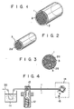
- Figs. 2 and 3 show an example of such a filler.
- a titanate coupling layer 3 is formed on the outer surface of a bundle 2a of fibrous conductive filler strands and a synthetic resin layer 1 is formed therearound.
- a bigger bundle of such filler bundles may be formed, and a synthetic resin layer 1 may be formed to surround its outer circumferential surface, as shown in Fig. 3.
- the number of fiber strands of the filler in each bundle 2a is not particularly limited, provided only that the total number of fibrous conductive filler strands included in the synthetic resin layer 1 is within the range of 100 to 50,000.
- cylindrical master pellets of circular cross-sectional shape have been illustrated, but cylindrical master pellets of other cross section such as squeezed or flattened shape (for example 6 mm length x 4 - 5 mm width ⁇ 1 ⁇ 2 mm thickness) may also be useful. These flattened master pellets can be more easily dispersed within natural pellet than those of circular cross section during feeding step into a hopper or molding step.
- titanate coupling agent useful for forming the titanate coupling layer 3 of the present invention may include isopropyltridodecylbenzene sulfonyl titanate, isopropyltris(dioctylpyrophosphate) titanate, bis(dioctylpyrophosphate) oxyacetate titanate, bis(dioctylpyrophosphate) ethylene titanate, iso- propyltri(dioctylphosphate) titanate, isopropyltricumylphenyl titanate, isopropyltri(N-aminoethyl. aminoethyl) titanate, or mixtures thereof.
- Table 1 shows the chemical formulas of these coupling agents.
- the pellets (master pellets) of the fibrous conductive filler of the present invention are generally mixed with the natural pellets in a mixing ratio in the range of from 1:1 to 1:20, based on weight.
- a method for manufacturing a molding material in which the master pellets are covered with a titanate coupling layer may now be described with reference to Fig. 4.
- One or more bundles 2a of a long fibrous conductive filler 2 are passed through a titanate coupling agent solution 11 for surface treatment.
- the bundle is passed through a die 13 of an extruder 12 for extruding a synthetic resin layer 1 therearound.
- the bundle is then cut to proper lengths by a cutting device 14 to provide master pellets 15.
- the master pellets 15 can be continuously obtained by this process.
- the master pellets 15 may be obtained by omitting the step of passing the conductive filler 2 through the titanate coupling agent solution, in the process shown in Fig. 4.
- Flattened master pellets may be obtained by positioning a pair of press rollers between the extruder 12 and the cutting device 14.
- the conductive synthetic resin molding material of the present invention may comprise natural pellets or a mixture thereof with another suitable material. Since the conductive synthetic resin molding material of the present invention has the configuration described above, it is easy to handle, presents no problems in the working environment, and provides an excellent dispersion of the filler in the resin. The molding material of the present invention thus allows for the molding of a product which has an excellent electromagnetic shielding effect and which sustains no degradation of its mechanical strength. Since the step of milling the conductive filler with the resin in a conventional method is eliminated, the number of steps is decreased.
- the bundle was coated with a thin polystyrene resin layer to have a diameter of about 2 mm.
- the bundle was cut into lengths of 5 mm to provide master pellets.
- Natural pellets of a polystyrene resin were mechanically mixed in an amount of 3 parts by volume with 1 part by volume of these master pellets to provide a conductive molding material.
- the obtained molding material was used for injection molding of a plate having a thickness of 3 mm.
- the molded plate had an electromagnetic shielding effect of 40 dB at 500 MHz.
- the conductive filler was uniformly dispersed within the molded plate and the plate did not sustain any decrease in mechanical strength, nor any degradation in other properties.
- Example 2 Four parts by volume of a polystyrene resin were mechanically mixed with one part by volume of a copper fiber having a diameter of about 50 pm and a length of 5 mm, to provide a conductive molding material.
- a plate was molded following the same procedures as those in Example 1. The obtained plate had an electromagnetic shielding effect of 20 dB at 500 MHz. The conductive filler was irregularly distributed in the plate, and the plate suffered a decrease in mechanical strength.
- a conductive molding material was prepared following the same procedures as those in Examples 2 and 3 above. Molded products were obtained following the same procedures as in Examples 2 and 3, except that coupling was not performed in Control 1 and a silane coupling agent was used in Control 2. The products obtained were subjected to the same tests of mechanical and electrical properties as those conducted in Examples 2 and 3. The results obtained are also shown in Table 2.
Description
- The present invention relates to a conductive synthetic resin molding material which, upon being molded, causes only a slight degradation in the mechanical strength of the synthetic resin, and which has an excellent electromagnetic shielding effect.
- To protect electronic circuits from external disturbance and to prevent the undesired leakage of electromagnetic waves from an oscillation circuit or the like, the casing of such electronic equipment must be made of an electromagnetic shielding material. The electromagnetic shielding material may be a metal, a conductive synthetic resin or the like. Although the former has an excellent electromagnetic shielding effect, it is disadvantageous, in that it is heavy, expensive and has poor workability. For this reason, the latter, a conductive synthetic resin, is currently in widest use.
- One method of rendering a synthetic resin electrically conductive includes the technique of forming a conductive layer on the surface of a synthetic molded product, either by application of a conductive paint or by spraying or plating a metal onto the synthetic resin product, as well as the internal addition technique of adding a conductive filler such as carbon, a metal powder or a fiber to the synthetic resin material itself. The former method requires a large number of steps and does not allow for easy mass-production. Furthermore, the conductive layer formed by this method may eventually peel after a long period of time. For this reason, the latter method is expected to be more practical.
- Despite its advantages, however, the latter method is also subject to the following problems. First, to obtain a desired electromagnetic shielding effect, a large amount of a conductive filler, such as carbon or a metal, must be mixed with the resin. This frequently results in poor dispersion of the filler or a low mechanical strength of the final product. Furthermore, when a metal or the like is added to the resin, the synthetic resin is degraded in its various properties. In addition to this, a metal fiber or a fibrous filler with good flexibility tends to become entangled in its initial form in a single substance. Thus, such a filler must be disentangled before addition to the resin. Uniform milling of the resin, together with such a filler, requires advanced skill and technology, due to differences in specific gravity and shape. An operator may also suffer from pain or itchiness in handling the fiber, which presents a problem in the working environment.
- According to US-A-4195 114 there is disclosed a plastic moulding pellet for use in manufacturing an electrically conductive plastic moulding suitable for shielding components from electromagnetic radiation, the plastic moulding pellet comprising a core in the form of at least one roving of metallised glass fibres and a surrounding body of a thermoplastic, each of the glass fibres being metallised over at least part of its circumference. Instead of glass fibres other dielectric, metallisable fibres may be used. US A4 258 101 is directed to a thermoplastic moulding pellet for moulding articles of plastic and metallised glass fibres wherein preferably the metallised glass fibres comprise an inner sub-bundle of fibres and an outer arrangement of fibres formed about the inner sub-bundle. US-A-4 332 853 is directed to a thermoplastic moulding pellet for moulding articles of plastic and metallised glass fibres wherein preferably the metallised glass fibres are arranged in a twist of sub-bundles of fibres around an inner sub-bundle. GB-A-2 047 253 disclosed similar fibre-containing thermoplastic resin composites except that the fibres may be carbon fibres. According to all these citations, it is aught to use-as a filler a glass fiber coated with a metal (or metallized glass fiber) or metallized carbon fiber.
- One object of the present invention is to provide a conductive synthetic resin material which is free from such problems in the working environment, which allows for the uniform dispersion of a conductive filler in a synthetic resin, which minimizes degradation of the mechanical strength of a plastic molded product upon the addition thereof, and which has an excellent electromagnetic shielding effect.
- To achieve the above object according to the present invention, a conductive synthetic resin molding material is provided, which comprises: master pellets consisting of a cylindrical synthetic resin layer and a bundle of metal fibers filled inside said synthetic resin layer in a longitudinal direction thereof, the master pellets being cut in the form of pellets; and natural pellets consisting of a synthetic resin.
- This invention can be more fully understood from the following detailed description when taken in conjunction with the accompanying drawings, in which:
- Fig. 1 is a perspective view of a master pellet according to the present invention;
- Fig. 2 is a perspective view of a bundle of metal fibers coated by a titanate coupling layer used in the present invention;
- Fig. 3 is a sectional view of a master pellet in which a bundle of a large number of the bundles of conductive filler shown in Fig. 2 is further coated with a synthetic resin layer; and
- Fig. 4 is a representation showing an example of the manufacture of the pellets of conductive filler according to the present invention.
- The preferred embodiment of the present invention may now be described with reference to the accompanying drawings.
- Fig. 1 shows a fibrous conductive filler coated with a synthetic resin (i.e. a master pellet) according to the present invention. The master pellet comprises a cylindrical synthetic resin layer 1 and a bundle of metal fibers as
conductive filler 2 filled within the layer 1 along the longitudinal direction thereof. - The fibrous
conductive filler 2 may be a fiber of a metal having a high electromagnetic shielding effect, such as copper, iron, nickel, aluminium or an alloy thereof. The fiber preferably has a small diameter and is generally used in a bundle of from 100 to 50,000 fiber strands. - The cylindrical synthetic resin layer 1 may consist of a thermoplastic resin such as a polystyrene resin, an ABS resin, a polycarbonate resin, or a modified PPO resin.
- The pellets of the fibrous conductive filler of the present invention are used after being admixed with general synthetic resin pellets (to be referred to as natural pellets, hereinafter). The synthetic resin of the synthetic resin layer 1 may be the same synthetic resin as that of the natural pellets, a resin which provides a reinforcing effect in synergism with the natural pellet resin, or a resin which forms a blend polymer with the natural pellet resin. For example, if it is desired to obtain a molded product of a styrene-type polymer, good results are obtained with a modified PPO resin, a polybutadiene resin, a polycarbonate resin or the like.
- To improve dispersion and adhesion within the resin of an objective plastic molded product and to prevent degradation of the mechanical strength of the plastic molded product, the fibrous conductive filler of the present invention may be formed by coating a titanate coupling agent onto the surface of a fibrous conductive filler bundle and, then, by covering the surface of the coupling layer with a synthetic resin layer.
- Figs. 2 and 3 show an example of such a filler. As shown in Fig. 2, a
titanate coupling layer 3 is formed on the outer surface of a bundle 2a of fibrous conductive filler strands and a synthetic resin layer 1 is formed therearound. A bigger bundle of such filler bundles may be formed, and a synthetic resin layer 1 may be formed to surround its outer circumferential surface, as shown in Fig. 3. In this case, the number of fiber strands of the filler in each bundle 2a is not particularly limited, provided only that the total number of fibrous conductive filler strands included in the synthetic resin layer 1 is within the range of 100 to 50,000. - In the above embodiments shown in Figs. 1 and 3, cylindrical master pellets of circular cross-sectional shape have been illustrated, but cylindrical master pellets of other cross section such as squeezed or flattened shape (for example 6 mm length x 4 - 5 mm width × 1 ~· 2 mm thickness) may also be useful. These flattened master pellets can be more easily dispersed within natural pellet than those of circular cross section during feeding step into a hopper or molding step.
- Examples of titanate coupling agent useful for forming the
titanate coupling layer 3 of the present invention may include isopropyltridodecylbenzene sulfonyl titanate, isopropyltris(dioctylpyrophosphate) titanate, bis(dioctylpyrophosphate) oxyacetate titanate, bis(dioctylpyrophosphate) ethylene titanate, iso- propyltri(dioctylphosphate) titanate, isopropyltricumylphenyl titanate, isopropyltri(N-aminoethyl. aminoethyl) titanate, or mixtures thereof. Table 1 (below) shows the chemical formulas of these coupling agents.
- The pellets (master pellets) of the fibrous conductive filler of the present invention are generally mixed with the natural pellets in a mixing ratio in the range of from 1:1 to 1:20, based on weight.
- A method for manufacturing a molding material in which the master pellets are covered with a titanate coupling layer may now be described with reference to Fig. 4. One or more bundles 2a of a long fibrous
conductive filler 2 are passed through a titanatecoupling agent solution 11 for surface treatment. The bundle is passed through a die 13 of anextruder 12 for extruding a synthetic resin layer 1 therearound. The bundle is then cut to proper lengths by acutting device 14 to providemaster pellets 15. Themaster pellets 15 can be continuously obtained by this process. If the coupling layer is not required, themaster pellets 15 may be obtained by omitting the step of passing theconductive filler 2 through the titanate coupling agent solution, in the process shown in Fig. 4. Flattened master pellets may be obtained by positioning a pair of press rollers between theextruder 12 and thecutting device 14. - The conductive synthetic resin molding material of the present invention may comprise natural pellets or a mixture thereof with another suitable material. Since the conductive synthetic resin molding material of the present invention has the configuration described above, it is easy to handle, presents no problems in the working environment, and provides an excellent dispersion of the filler in the resin. The molding material of the present invention thus allows for the molding of a product which has an excellent electromagnetic shielding effect and which sustains no degradation of its mechanical strength. Since the step of milling the conductive filler with the resin in a conventional method is eliminated, the number of steps is decreased.
- Three hundred elongated copper fiber strands, each having a diameter of about 50 um, were bundled together. The bundle was coated with a thin polystyrene resin layer to have a diameter of about 2 mm. The bundle was cut into lengths of 5 mm to provide master pellets. Natural pellets of a polystyrene resin were mechanically mixed in an amount of 3 parts by volume with 1 part by volume of these master pellets to provide a conductive molding material. The obtained molding material was used for injection molding of a plate having a thickness of 3 mm. The molded plate had an electromagnetic shielding effect of 40 dB at 500 MHz. The conductive filler was uniformly dispersed within the molded plate and the plate did not sustain any decrease in mechanical strength, nor any degradation in other properties.
- Four parts by volume of a polystyrene resin were mechanically mixed with one part by volume of a copper fiber having a diameter of about 50 pm and a length of 5 mm, to provide a conductive molding material. A plate was molded following the same procedures as those in Example 1. The obtained plate had an electromagnetic shielding effect of 20 dB at 500 MHz. The conductive filler was irregularly distributed in the plate, and the plate suffered a decrease in mechanical strength.
- In accordance with the composition shown in Table 2 below, 300 strands of an elongated copper fiber having a diameter of about 50 Ilm were bundled together. After pickling and drying, the bundle was passed through a titanate coupling agent solution to perform surface treatment of the copper fiber. A polystyrene resin layer was extrusion coated on the thus obtained conductive filler having a titanate coupling layer until the bundle had a diameter of about 2 mm. The bundle was then cut into lengths of 5 mm to provide master pellets. Two parts by volume of natural pellets of a polystyrene resin were mechanically mixed with one part by volume of the master pellets to manufacture a conductive molding material. The molding material was injection molded to obtain a molded product. The product was subjected to tests of its mechanical and electrical properties. The results obtained are shown in Table 2 below.
- A conductive molding material was prepared following the same procedures as those in Examples 2 and 3 above. Molded products were obtained following the same procedures as in Examples 2 and 3, except that coupling was not performed in Control 1 and a silane coupling agent was used in
Control 2. The products obtained were subjected to the same tests of mechanical and electrical properties as those conducted in Examples 2 and 3. The results obtained are also shown in Table 2.
Claims (13)
Applications Claiming Priority (4)
| Application Number | Priority Date | Filing Date | Title |
|---|---|---|---|
| JP124734/83 | 1983-07-11 | ||
| JP12473583A JPS6018315A (en) | 1983-07-11 | 1983-07-11 | Conductive molding material |
| JP124735/83 | 1983-07-11 | ||
| JP58124734A JPS6018314A (en) | 1983-07-11 | 1983-07-11 | Conductive molding material |
Publications (3)
| Publication Number | Publication Date |
|---|---|
| EP0131067A1 EP0131067A1 (en) | 1985-01-16 |
| EP0131067B1 true EP0131067B1 (en) | 1988-01-07 |
| EP0131067B2 EP0131067B2 (en) | 1995-08-16 |
Family
ID=26461349
Family Applications (1)
| Application Number | Title | Priority Date | Filing Date |
|---|---|---|---|
| EP83109901A Expired - Lifetime EP0131067B2 (en) | 1983-07-11 | 1983-10-04 | Conductive synthetic resin molding material |
Country Status (3)
| Country | Link |
|---|---|
| US (1) | US4530779A (en) |
| EP (1) | EP0131067B2 (en) |
| DE (1) | DE3375248D1 (en) |
Families Citing this family (23)
| Publication number | Priority date | Publication date | Assignee | Title |
|---|---|---|---|---|
| NL193609C (en) * | 1981-12-30 | 2000-04-04 | Bekaert Sa Nv | Composite strand for processing as granulate in plastic products and method for manufacturing a plastic mixing granulate. |
| JPS61111335A (en) * | 1984-11-05 | 1986-05-29 | Dainippon Toryo Co Ltd | Molding of plastic |
| JPS6245659A (en) * | 1985-08-23 | 1987-02-27 | Eng Plast Kk | Electrically conductive molding material |
| EP0221434B1 (en) * | 1985-11-04 | 1990-03-14 | General Electric Company | Improving conductivity of plastics containing metallic fillers |
| US4816184A (en) * | 1987-02-20 | 1989-03-28 | General Electric Company | Electrically conductive material for molding |
| EP0306671A1 (en) * | 1987-07-20 | 1989-03-15 | Hitachi, Ltd. | Electroconductive resin composition for moulding, and shield moulded therefrom |
| DE3804381C2 (en) * | 1988-02-12 | 1993-10-28 | Sachsenwerk Ag | Ohmic voltage divider for a high voltage system |
| DE3810597A1 (en) * | 1988-03-29 | 1989-10-12 | Bayer Ag | METALIZED FIBERS CONTAINING COMPOSITES AND THEIR USE FOR THE MANUFACTURE OF ELECTROMAGNETIC SHIELDED PARTS |
| DE3810598A1 (en) * | 1988-03-29 | 1989-10-12 | Bayer Ag | COMPOSITIONS CONTAINING METAL FIBERS AND THE USE THEREOF FOR PRODUCING MOLDED PARTS FOR SHIELDING ELECTROMAGNETIC RADIATION |
| FR2652943B1 (en) * | 1989-10-05 | 1994-07-01 | Electricite De France | CONDUCTIVE MATERIAL FOR ELECTRODE, ELECTRICAL COMPONENT AND MANUFACTURING METHOD THEREOF. |
| NL9201447A (en) * | 1992-08-12 | 1994-03-01 | Hul A J Van Den Bv | Single or multi-core electrically conductive cable, more particularly for signal transmission. |
| US7078098B1 (en) | 2000-06-30 | 2006-07-18 | Parker-Hannifin Corporation | Composites comprising fibers dispersed in a polymer matrix having improved shielding with lower amounts of conducive fiber |
| US20020108699A1 (en) * | 1996-08-12 | 2002-08-15 | Cofer Cameron G. | Method for forming electrically conductive impregnated fibers and fiber pellets |
| US5766979A (en) | 1996-11-08 | 1998-06-16 | W. L. Gore & Associates, Inc. | Wafer level contact sheet and method of assembly |
| US5830565A (en) * | 1996-11-08 | 1998-11-03 | W. L. Gore & Associates, Inc. | High planarity and low thermal coefficient of expansion base for semi-conductor reliability screening |
| US5886535A (en) * | 1996-11-08 | 1999-03-23 | W. L. Gore & Associates, Inc. | Wafer level burn-in base unit substrate and assembly |
| US5896038A (en) * | 1996-11-08 | 1999-04-20 | W. L. Gore & Associates, Inc. | Method of wafer level burn-in |
| US5966593A (en) * | 1996-11-08 | 1999-10-12 | W. L. Gore & Associates, Inc. | Method of forming a wafer level contact sheet having a permanent z-axis material |
| US5909123A (en) * | 1996-11-08 | 1999-06-01 | W. L. Gore & Associates, Inc. | Method for performing reliability screening and burn-in of semi-conductor wafers |
| US5966022A (en) * | 1996-11-08 | 1999-10-12 | W. L. Gore & Associates, Inc. | Wafer level burn-in system |
| JP4485117B2 (en) * | 2002-06-27 | 2010-06-16 | 日東電工株式会社 | Protective peeling film |
| KR101211134B1 (en) * | 2012-02-13 | 2012-12-11 | 금호석유화학 주식회사 | A method for preparing carbon nano material/polymer composites |
| US20140272417A1 (en) * | 2013-03-15 | 2014-09-18 | Integral Technologies, Inc. | Moldable capsule and method of manufacture |
Family Cites Families (8)
| Publication number | Priority date | Publication date | Assignee | Title |
|---|---|---|---|---|
| US3708387A (en) * | 1970-09-11 | 1973-01-02 | Univ Drexel | Metallic modified plastic compositions and method for the preparation thereof |
| US3983195A (en) * | 1971-07-16 | 1976-09-28 | Hasbro Industries, Inc. | Pencil sheath compositions, method for making pencils |
| US4195114A (en) * | 1976-12-28 | 1980-03-25 | International Business Machines Corporation | Conductive plastic and method of preparation |
| US4332853A (en) * | 1977-05-09 | 1982-06-01 | International Business Machines Corporation | Conductive plastic with metalized glass fibers retained in partial clumps |
| SE7803576L (en) * | 1978-03-30 | 1979-10-01 | Jensen Mogens P | TOOL FOR DRAWING LOOSE HARD FIXED OBJECT |
| US4388422A (en) * | 1979-04-16 | 1983-06-14 | Dart Industries Inc. | Fiber-reinforced composite materials |
| US4367745A (en) * | 1980-05-27 | 1983-01-11 | Minnesota Mining And Manufacturing Company | Conformable electrically conductive compositions |
| US4438059A (en) * | 1982-09-22 | 1984-03-20 | Molded Fiber Glass Companies | Electrically conductive fiber glass articles and sheets |
-
1983
- 1983-10-04 DE DE8383109901T patent/DE3375248D1/en not_active Expired
- 1983-10-04 EP EP83109901A patent/EP0131067B2/en not_active Expired - Lifetime
- 1983-10-11 US US06/540,563 patent/US4530779A/en not_active Expired - Lifetime
Also Published As
| Publication number | Publication date |
|---|---|
| DE3375248D1 (en) | 1988-02-11 |
| US4530779A (en) | 1985-07-23 |
| EP0131067B2 (en) | 1995-08-16 |
| EP0131067A1 (en) | 1985-01-16 |
Similar Documents
| Publication | Publication Date | Title |
|---|---|---|
| EP0131067B1 (en) | Conductive synthetic resin molding material | |
| US5397608A (en) | Plastic article containing electrically conductive fibers | |
| US4816184A (en) | Electrically conductive material for molding | |
| EP0117700A1 (en) | Rigid resin composition having electromagnetic shielding properties | |
| US4500595A (en) | Stainless steel fiber-thermosplastic granules and molded articles therefrom | |
| US4388422A (en) | Fiber-reinforced composite materials | |
| EP1446446B1 (en) | Process for producing electrically conductive thermoplastic compositions | |
| DE3248658C2 (en) | Plastic articles, process for their preparation and intermediates | |
| CA2413040C (en) | Composites comprising fibers dispersed in a polymer matrix having improved shielding with lower amounts of conductive fiber | |
| US6268408B1 (en) | Conductive fire-retardant thermoplastic elastomer mixture | |
| EP0304435B1 (en) | Electrically conductive material for molding | |
| CA1101169A (en) | Conductive plastic with metalized glass fibers retained in partial clumps | |
| US5746956A (en) | Process and apparatus for manufacturing aluminum laminally filled plastic pellets for shielding electromagnetic interference | |
| JPS5922710A (en) | Manufacture of electroconductive molding material | |
| JPS60179204A (en) | Manufacture of chip for shielding electromagnetic wave composition | |
| EP0267292B1 (en) | Method for manufacturing pellets for making electromagnetic wave shielding material | |
| JPS61296066A (en) | Electrically-conductive molding material | |
| JPH01148515A (en) | Manufacture of electroconductive fiber composite resin | |
| JPS6213444A (en) | Electrically conductive resin composition | |
| DE10222459A1 (en) | Composite material for ultrahigh frequency screening, e.g. to protect electronics, contains ferrite powder modified with conductive polymer, electrically-conductive non-metallic particles and organic binder | |
| JPH0725935B2 (en) | Conductive plastic molding material | |
| JP2633920B2 (en) | Molding resin composition having conductivity and electromagnetic wave shielding structure | |
| JPS59210957A (en) | Electrically conductive plastic film or sheet | |
| JPS6018314A (en) | Conductive molding material | |
| JPH03145006A (en) | Conductive resin composition |
Legal Events
| Date | Code | Title | Description |
|---|---|---|---|
| PUAI | Public reference made under article 153(3) epc to a published international application that has entered the european phase |
Free format text: ORIGINAL CODE: 0009012 |
|
| AK | Designated contracting states |
Designated state(s): DE FR GB |
|
| 17P | Request for examination filed |
Effective date: 19850306 |
|
| RAP1 | Party data changed (applicant data changed or rights of an application transferred) |
Owner name: TOSHIBA CHEMICAL CORPORATION |
|
| GRAA | (expected) grant |
Free format text: ORIGINAL CODE: 0009210 |
|
| AK | Designated contracting states |
Kind code of ref document: B1 Designated state(s): DE FR GB |
|
| REF | Corresponds to: |
Ref document number: 3375248 Country of ref document: DE Date of ref document: 19880211 |
|
| ET | Fr: translation filed | ||
| PLBI | Opposition filed |
Free format text: ORIGINAL CODE: 0009260 |
|
| 26 | Opposition filed |
Opponent name: BAYER AG, LEVERKUSEN KONZERNVERWALTUNG RP PATENTAB Effective date: 19880914 |
|
| PUAH | Patent maintained in amended form |
Free format text: ORIGINAL CODE: 0009272 |
|
| STAA | Information on the status of an ep patent application or granted ep patent |
Free format text: STATUS: PATENT MAINTAINED AS AMENDED |
|
| 27A | Patent maintained in amended form |
Effective date: 19950816 |
|
| AK | Designated contracting states |
Kind code of ref document: B2 Designated state(s): DE FR GB |
|
| ET3 | Fr: translation filed ** decision concerning opposition | ||
| PGFP | Annual fee paid to national office [announced via postgrant information from national office to epo] |
Ref country code: FR Payment date: 19981008 Year of fee payment: 16 |
|
| PGFP | Annual fee paid to national office [announced via postgrant information from national office to epo] |
Ref country code: GB Payment date: 19981009 Year of fee payment: 16 |
|
| PGFP | Annual fee paid to national office [announced via postgrant information from national office to epo] |
Ref country code: DE Payment date: 19981223 Year of fee payment: 16 |
|
| PG25 | Lapsed in a contracting state [announced via postgrant information from national office to epo] |
Ref country code: GB Free format text: LAPSE BECAUSE OF NON-PAYMENT OF DUE FEES Effective date: 19991004 |
|
| GBPC | Gb: european patent ceased through non-payment of renewal fee |
Effective date: 19991004 |
|
| PG25 | Lapsed in a contracting state [announced via postgrant information from national office to epo] |
Ref country code: FR Free format text: LAPSE BECAUSE OF NON-PAYMENT OF DUE FEES Effective date: 20000630 |
|
| PG25 | Lapsed in a contracting state [announced via postgrant information from national office to epo] |
Ref country code: DE Free format text: LAPSE BECAUSE OF NON-PAYMENT OF DUE FEES Effective date: 20000801 |
|
| REG | Reference to a national code |
Ref country code: FR Ref legal event code: ST |
|
| APAH | Appeal reference modified |
Free format text: ORIGINAL CODE: EPIDOSCREFNO |